Transcription
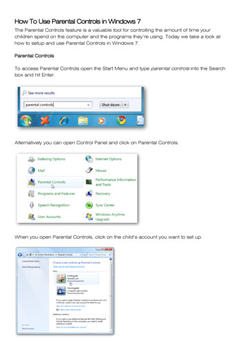
Technical Reference ManualScadaFlex PicoBrickDistributed I/O & RTU Modules 7 Models Available:12 Discrete Inputs (12/24 or 120V)12 Discrete FET (protected transistor) Outputs16-bit Analog Inputs - 5Vdc16-bit Analog Inputs - 20mA12-bit Analog Outputs - 20mACombo [3 16-bit AI, 3 DI (12/24 or 120V), 2 DO ]Discrete I/O 6 Discrete Inputs (12/24 or 120V) 6 Discrete FET Outputs Modular I/O Expansion to 3000 points distributed over 4,000ft.Support for Modbus RTU, BrickNet peer-to-peer, and DF1communicationsBack-to-back I/O bridge – Master ModeBuilt-in “store-and-forward” messaging for radio based systemsDual-standard communications interface; RS-232 and RS-485All I/O is isolated and transient, surge, overload and polarity protectedAll Discrete Inputs have pulse and runtime totalizers, and rateAll Discrete Outputs have programmable Flash functionAll Analog Inputs have totalizers with programmable sampling timeDual Watchdog Timers; Comm & Module CPULow-power DC for battery/solar applicationsHot-swappable with removable terminal blocksDiscrete I/O have individual LED status indicatorsCompact & DIN rail mounting for lower panel cost-40 C to 75 C Operating Temperature Range3-year factory warranty oo
PicoBrick Distributed I/O ModulesPicoBrick Distributed I/OTechnical Reference ManualCopyright NoticeThis document is copyrighted, 2007, by Industrial Control Links, Inc.All rights are reserved.Industrial Control Links, Inc. reserves the right to make improvements to the products described in thismanual at any time without notice.No part of this manual may be reproduced, copied, translated or transmitted in any form or by any meanswithout the prior written permission of Industrial Control Links, Inc. Information provided in this manual isintended to be accurate and reliable. However, Industrial Control Links, Inc. assumes no responsibility for itsuse, nor for any infringements upon the rights of third parties which may result from its use.AcknowledgmentsScadaFlex, ScadaFlex Plus, ScadaWorks, ScadaBuilder, PicoBrick and PicoBrick are trademarks ofIndustrial Control Links, Inc.ISaGRAF is a trademark of ICS Triplex, Inc.IBM and PC are trademarks of International Business Machines Corporation2Copyright 2007 Industrial Control Links, Inc. All Right Reserved
PicoBrick Distributed I/O ModulesIn This Manual . . .This manual provides the technical hardware information required for systemdesign and installation of PicoBrick Distributed I/O Modules.If you have just purchased a PicoBrick, we hope that you are as pleased using itas we have been developing it.If you are reading this manual looking at a future purchase, we hope that youwill consider PicoBrick I/O when you have an application that needs modularI/O expansion or a low-cost RTU.SupportIf you have questions or need help with an application, we hope that you’ll takeadvantage of our free technical support. Simply call us at:(800) 888-1893If you need to send us a fax, use either:(530) 888-1300 or (530) 888-7017If you prefer e-mail, especially if you want to send us a sample of a program orother files, you can e-mail us at:support@www.iclinks.comFor additional technical information including datasheets, manuals andsoftware, visit our web site at:www.iclinks.comCopyright 2007 Industrial Control Links, Inc. All Right Reserved3
PicoBrick Distributed I/O Modules4Copyright 2007 Industrial Control Links, Inc. All Right Reserved
PicoBrick Distributed I/O ModulesCertificationsPicoBrick I/O Modules are tested to the following certifications:North America:UL 508, CSA 142, ANSI/ISA-12.12.01-2000: April , CSA-C22.2 NO. 213-Ml987 (R 1999);Class I Division 2 Groups A, B, C, and D: by INTERTEK.European Union:EN 60079-15: Sept 2003 ATEX Group II Category 3 Gas Vapor or Mist ExplosionprotectionProtection Type nA: In normal and some abnormal conditions, the equipment is not capable ofigniting an explosive gas atmosphere.All certified PicoBrick I/O Modules come with the following compliance marking tagATEX Explosion protection Group II Category 3, Gas Vapor ormist (not suitable for incendiary dust environments).CE Certification MarkingClass 1 Div 2Compliance“X” Device must be installed within anIP56, IP54, Nema 4, or Nema 4xenclosure. External surgesuppression must be installedexternally to limit input voltage to140% of operating voltages.“T5” Rating to100ºC MaximumSurfaceTemperatureAmbient OperatingTemperatureClass 1 Div 2WarningATEXWarningCopyright 2007 Industrial Control Links, Inc. All Right Reserved5
PicoBrick Distributed I/O ModulesContentsCertifications . 5North America: .5European Union: .5Introduction . 9Modular I/O Expansion.9Built-in Networking .9Open Architecture .9Peer-to-peer Communications .9Local I/O Processing .10Wide Power Range and Low Power Operation .10Internal Power Monitor .10Dual Watchdog Timers.10Rugged I/O.11Industry Leading Warranty .11PicoBrick Familiarization . 12Power . 14Power Wiring.14Communications Interfaces . 15RS-232 Serial Communications Interface .15RS-485 Serial Communications Interface .15RTU Configuration with the I/O Toolbox: Communications .16RTU Configuration with the I/O Toolbox: Master Mode.17Modbus Communications . 18Network Addressing .19Store & Forward.19BrickNet Communications . 22DF1 Communications . 27Maintenance . 28Analog Calibration.28Firmware Updates.28Mechanical Installation. 29North America: .29European Union: .29Electrical Installation . 29Class 1 Division 2 Group A, B, C, and D Requirements.29Discrete Input Modules. 32Signal Types and Levels .32LED Input Status Indicators .32I/O Processor Functions.32Input Filtering .32Pulse Totalization.32Runtime Totalization .336Copyright 2007 Industrial Control Links, Inc. All Right Reserved
PicoBrick Distributed I/O ModulesPulse Rate Calculation.33Field Wiring .34Modbus Register Map .35Specifications - Discrete Input PicoBricks .36Discrete Output Module. 37LED Output Status Indicators.37I/O Processor Functions.37Field Wiring .38Modbus Register Map .39Specifications - Discrete Output PicoBrick .40Discrete I/O Modules. 41Discrete I/O Module Discrete Input Section.41Signal Types and Levels . 41LED Input Status Indicators . 41I/O Processor Functions. 42Input Filtering . 42Pulse Totalization. 42Runtime Totalization . 42Pulse Rate Calculation. 42Discrete I/O Module Discrete Output Section.43LED Output Status Indicators. 43I/O Processor Functions - Discrete Outputs. 43Discrete I/O Module Field Wiring.44Modbus Register Map .45Specifications - Discrete Input PicoBricks .46Analog Input Modules. 48Signal Types and Levels .48Isolation and Input Protection.48I/O Processor Functions.48Calibration.48Field Wiring .49Modbus Register Map .50Modbus Register Map .51Specifications - Analog Input PicoBricks .52Analog Output Module. 53Signal Types and Levels .53Isolation and Output Protection.53Calibration.53Field Wiring .53Modbus Register Map .55Specifications - Analog Output PicoBrick .56“Combo” I/O Modules. 57Combo Module Discrete Input Section.57Signal Types and Levels . 57LED Input Status Indicators . 57I/O Processor Functions. 58Input Filtering . 58Copyright 2007 Industrial Control Links, Inc. All Right Reserved7
PicoBrick Distributed I/O ModulesPulse Totalization. 58Runtime Totalization . 58Pulse Rate Calculation. 58Combo Module Discrete Output Section .59LED Output Status Indicators. 59I/O Processor Functions - Discrete Outputs. 59Combo Module Analog Input Section.60Signal Types and Levels . 60Isolation and Input Protection. 60I/O Processor Functions. 61Analog Input Calibration. 61Combo Module Field Wiring.61Modbus Register Map .63Specifications - Combo I/O PicoBricks.648Copyright 2007 Industrial Control Links, Inc. All Right Reserved
PicoBrick Distributed I/O ModulesIntroductionPicoBricks are easy-to-use distributed I/O modules. They can be connected toScadaFlex or EtherLogic controllers for I/O expansion, connected toProgrammable Logic Controllers (PLCs) or PC computers as rugged field I/O, orused with radios or leased-line modems to serve as low-cost Remote TerminalUnits (RTUs).PicoBricks go beyond traditional “dumb” I/O modules by providing localintelligent signal conditioning and data acquisition.Modular I/O ExpansionPicoBricks provide a very modular means of adding I/O capacity as needed,without the extra cost, wasted space and constraints of card racks. Need moreI/O? Snap on a module. Want to add some I/O a few hundred yards away?String a single twisted pair of wires and you’re up and running!Built-in NetworkingPicoBricks come network-ready with a dual-function (RS-485 and RS-232)serial communications interface. The RS-485 port can be used for low-cost 2wire networking while RS-232 is a simple point-to-point interface to radios andmodems as well as PCs. PicoBricks support “store-and-forward” messaging toextend the effective range of radio based systems by using the RTU as a digitalrepeater, without additional radio hardware.Open ArchitecturePicoBricks use the Modbus RTU protocol, one of the most common protocolsused in control systems. This protocol is supported by thousands of otherhardware and software products including all of the common PC-based MMIsoftware packages from manufacturers such as Wonderware, Intellusion,Iconics, and National Instruments. Picobricks also talk DF1 but require aToolbox configuration to do so. The change is not automatic.Peer-to-peer CommunicationsFor true peer-to-peer operation Picobrick modules support ICL’s BrickNetprotocol for use with ICL EtherLogic and ScadaFlex Plus controller families.Protocol detection between Modbus and BrickNet is automatic.Copyright 2007 Industrial Control Links, Inc. All Right Reserved9
PicoBrick Distributed I/O ModulesLocal I/O ProcessingPicoBricks perform local I/O processing to off-load time-sensitive operationsfrom a Host system.PicoBricks with Discrete Inputs totalize input transitions and on-time (runtime)and calculate pulse rates for every input. Applications include using digitalpulse output meters for precise totalized flow and wattage calculations, as wellas real-time flow rate and power usage information. Runtime is widely used forwear leveling between pumps or motors, and as the basis of an equipmentpreventive maintenance program.PicoBricks with Analog Inputs totalize the value of every Analog Input at aperiodic sampling rate, especially useful for totalized flows and wattageapplications using analog output type meters.PicoBricks with Discrete Outputs can be commanded to flash individualoutputs at a precise periodic rate independent of communications and I/O scanrates, primarily for alarm annunciation.Wide Power Range and Low Power OperationPicoBricks are designed for use in solar and battery backed applications. Theyoperate over a wide range of DC power (10 to 28Vdc) and consume very littlepower.Internal Power MonitorAll PicoBricks have an internal analog input channel to monitor the inputvoltage (power) level. The input voltage may be read in a Modbus register. Thisfeature is especially useful in battery backed and solar applications to checkthe actual battery voltage level under load.Dual Watchdog TimersPicoBricks have two watchdog timers; one that monitors the sanity of theinternal microprocessor, the second that monitors activity on thecommunications link.The first watchdog timer will automatically reset and restart the modulesmicroprocessor if it senses that it is not operating properly. This timer is notuser configurable.The second timer will reset all outputs (analog or discrete) if there is nocommunications activity for a preset period of time. This timer is user settablevia a Modbus register. Setting the timer to “0” disables this feature. This timeris used when it is critical to stop equipment when the communications link isbroken and the “Host” system is no longer in control. An example is shutting offpumps at a pumping station when there is a broken communications link sothat the pumps do not continue to run forever without a “stop” signal.10Copyright 2007 Industrial Control Links, Inc. All Right Reserved
PicoBrick Distributed I/O ModulesRugged I/OAll field I/O interfaces are isolated and protected against overloads, transients,surges, and reverse polarity. Transorb transient protectors and self resettingpolymer fuses are used throughout. When the fault condition is corrected, themodule automatically resumes normal operation.Industry Leading WarrantyPicoBricks are backed by an industry leading 3-year factory warranty.Copyright 2007 Industrial Control Links, Inc. All Right Reserved11
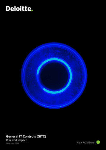
PicoBrick Distributed I/O ModulesPicoBrick FamiliarizationThe diagram below highlights the main physical features of PicoBrick I/O Modules that are discussed in thefollowing pages.2Analog Input Mode Switches( Combo Modules only)4High density I/O, up to12 points per module3CommunicationsStatus LEDHot-swappableSerial Communications1 (RS-232 / RS-485 Port)& DC Power Connector635mm. DIN Rail Mounting7Power/Status LED8Hot-swappable10 I/O Terminal Blocks1Local signal processingwith totalization, runtimeand rate calculations59Network Address SwitchI/O Status LEDs(Discrete I/O)Hot-swappable Serial Communications & DC Power ConnectorsRemovable terminal blocks for RS-232/RS-485 Communications and DC Power. The RS-485 interfacesupports up to 256 PicoBricks on a single network. DC Power is 10 to 28Vdc.2Communications Status LEDBicolor (red/green) Transmit and Receive Data LED indicator shows network communications activity; REDfor receive data (into PicoBrick), GREEN for transmit data (from PicoBrick).3High Density I/OUp to 12 Discrete I/O points, 8 Analog Input points or 6 Analog Output Points per module. The compactPicoBrick package saves precious panel space and makes it easy to retrofit systems with more I/O.4Analog Input Mode SwitchesCombo I/O Modules have built-in selectable precision current sense resistors that are switched out forVoltage mode or in for Current mode on each analog input channel. Accommodates both voltage andcurrent output sensors without buying two separate modules.5Local Signal ProcessingPicoBricks totalize Discrete Input transitions, runtime and pulse rate. Discrete Outputs have programmableFlash function. Analog Inputs have noise rejection signal processing and totalization.12Copyright 2007 Industrial Control Links, Inc. All Right Reserved
PicoBrick Distributed I/O Modules635mm. DIN Rail MountingPicoBricks snap onto a standard 35mm. DIN rail. A release catch is accessible under the lower I/O terminalblock (unplug terminal block for access).7Power/Status LEDCombined function LED status indicator. On solid GREEN for normal operation (power ON), flashes RED forcommunications failure.8Network Address Switch16-position rotary switch for easy front panel selection of the PicoBricks network address. The actualnetwork address is the switch setting plus a base address in a Modbus register in EEROM. The default baseaddress is zero, but configuring the base address allows PicoBrick to be set to any of the possible 255Modbus addresses. PicoBricks always respond to address 255 regardless of the switch and EEROMsettings, in order to simplify setup. Do not use 255 as an address in a network! Address 0 is not supported.9Discrete I/O Status LEDsModules with Discrete Inputs/Outputs have amber LED status indicators right above the field wiring terminalblocks to simplify system test and troubleshooting.10Hot-swappable I/O Terminal BlocksI/O Terminal Blocks can be removed and reinserted easily, without taking your system down.Copyright 2007 Industrial Control Links, Inc. All Right Reserved13
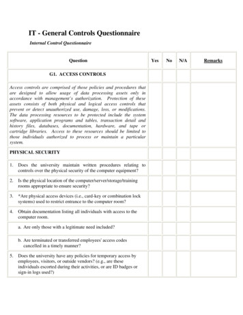
PicoBrick Distributed I/O ModulesPowerPicoBricks are designed to operate from DC power, typically either 12 or 24volts, although they are specified to operate over a range of 10 to 28Vdc. Thepower consumption of a PicoBrick is very low; typically about 30mA (0.030A) to50mA (0.050A). Because of their low power consumption and wide input powerrange, they are ideal for solar or battery backed applications.The ScadaFlex DC Power Supply or ScadaFlex UPS are recommended powersources because they both have the same wide range temperature rating asPicoBricks as well as ICL's ScadaFlex Plus and EtherLogic Series Controllers.The ScadaFlex UPS is especially worth considering as economical insuranceagainst unreliable “brownout” prone AC power sources.Power WiringOn the front face of all PicoBricks is a single removable terminal block withterminations for both communications and power. The power connections arethe two terminals located towards the bottom of the terminal block. They arelabeled “PWR” on one side, and ( ) and (-) on the other.Typical DC power wiring to a PicoBrick I/O module is shown below:TX232RXGND485 DC Power In-PWR 12 / 24 vTypical DC Power Wiring - PicoBrick I/O Module14Copyright 2007 Industrial Control Links, Inc. All Right Reserved
PicoBrick Distributed I/O ModulesCommunications InterfacesThe most common serial communications standards for SCADA and industrialcontrol systems are RS-232 for short point-to-point connections and RS-485 forlonger point-to-point and networked communications. PicoBricks have a dualinterface serial port that supports both RS-232 and RS-485 operation.The communications connect
For true peer-to-peer operation Picobrick modules support ICL's BrickNet protocol for use with ICL EtherLogic and ScadaFlex Plus controller families. Protocol detection between Modbus and BrickNet is automatic.