Transcription
ExR-1 RobotOperating Guide
ResponsibleName:Ian Peerless[Person who is responsible forwriting the document, i.e.author]Job Title:DirectorSignature:Date:Accountable[Person who is accountable forthe quality, validity andtimeliness of the document, i.e.Process Owner]Consulted on this documentName:Ian PeerlessJob Title:DirectorSignature:Date:Names:Ronald SchreursversionDorian Scholz[Persons who have endorsedthe document]Alberto RomayInformedNames:All ExR employees, ER employeesand fleet managers.[Persons who have beeninformed of this version of thedocument]ExRobotics B.V.ExR-1 RobotOperating GuideDocument No.:20190122IP1Version No.: 11Owner:Date:Ian Peerless2020-03-31Page 1 of 23This document is considered an uncontrolled copy when printed. Always ensure that you print and use a current version.Copyright 2020 ExRobotics B.V.
Document Change Log:Version#Date of reissueChanges -16102019-12-02112020-03-31First draftUpdated software description & completedSections 7 and 8Incorporated comments from Iwan & DorianIncluded customer commentsUpdated gamepad information, trackreplacement, and chili-tag positioning. Minorpoints of clarification based on deployments.Renamed document & added mission planning &reportingAdded fleet status screen, gas alarmadjustments, gamepad blue button, autonomyjunctions, mission reports withvideos/recordings/snapshots, questions &answers.Revised use of the “Keep awake” buttonAlarm if autonomous mission is interruptedLaunching an autonomous mission explained“Spot turn” limitations expandedCorrected docking station electrical connectionsSimpler chili-tags at waypoints explainedWhy doesn’t my controller work?How do I wash a contaminated robot?Added video recording to remote control screenUpdated screen shotsClarified how to set up waypoint tasksAdded how to set up junctionsAdded new view options to Mission ReportAdded ExR-1 specificationsUpdated how to launch a mission and explained“Site Config” & “Feedback” options.Added cold weather behaviour to Q&ARemoved “hibernation” feature & refinedcharger wording.Added a remark about auto-immobilisation.Added picture of docking station buffer bolt.Added image and description of new “UserManagement” screen.Added typical data consumption & battery life.Robot specifications updated.ExRobotics B.V.ExR-1 RobotOperating GuideDocument No.:20190122IP1Version No.: 11PageManyAuthor ofChangeIan PeerlessIan PeerlessManyMany5, 10 &12Ian PeerlessIan PeerlessIan Peerless5Ian Peerless6, 7, 9,14, 16Ian Peerless7910111214181877,119,1010,1111208,11Ian Peerless205,6,8Ian PeerlessAlbertoRomayIan PeerlessAlbertoRomayIan Peerless1213141921 - 23Owner:Date:Ian Peerless2020-03-31Page 2 of 23This document is considered an uncontrolled copy when printed. Always ensure that you print and use a current version.Copyright 2020 ExRobotics B.V.
Contents1.Introduction . 42.Robots . 43.Control Stations . 54.Docking Stations . 55.Cloud Software . 65.1.Fleet Management and Status . 65.2.Robot Control . 75.3.Mission Editor . 95.4.Mission Report . 116.Operative Training . 127.Deployment . 127.1.Preparations . 127.2.Authorisation and Authentication . 147.3.Robot Delivery . 147.4.Setting up autonomous routes . 157.5.Setting up waypoints . 158.Operations. 178.1.Customer support . 178.2.Software releases . 178.3.Routine Maintenance . 178.4.Replacing tracks . 178.5.Calibrating gas detectors . 188.6.Security . 189.Questions and Answers . 199.1.Why can’t I connect to a robot? . 199.2.Why has my robot stopped working in cold weather? . 199.3.Why doesn’t my controller work? . 199.4.How much data will the robot transfer over its wireless connection? . 199.5.How long will the robot’s batteries last?. 199.6.Why have I experienced unexpected behaviour while operating a robot? . 209.7.How do I wash a contaminated robot? . 209.8.Does the induction charger generate harmful magnetic fields? . 2010.ExR-1 Robot Specifications . 2110.1.Worksite and Climate . 2110.2.Mobility Platform & Chargers . 2110.3.Sensing . 2210.4.Connectivity Control & Monitoring . 22ExRobotics B.V.ExR-1 RobotOperating GuideDocument No.:20190122IP1Version No.: 11Owner:Date:Ian Peerless2020-03-31Page 3 of 23This document is considered an uncontrolled copy when printed. Always ensure that you print and use a current version.Copyright 2020 ExRobotics B.V.
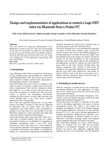
1.IntroductionThis document is one of two that will help operators to use their ExR-1 robots safely andeffectively. The documents are the “ExR-1 Robot Operating Instructions” and the “ExR-1 RobotOperating Guide”. The former focuses on the safe operation of the robot especially with respectto its use in potentially explosive gas environments. The latter provides additional informationabout the robot and its use. If there’s a conflict between the documents, the instructions willalways prevail.This robot operating guide:Describes each key part of the robot system:o Robots.o Control stations that are used to communicate with the robot.o Docking stations that recharge the robots’ batteries.o Cloud software that enables users to interact with robots. Recommends how robot operatives should be trained. Presents the steps required when deploying robots. Provides advice for operating robots.The guide will be updated and sent to robot fleet managers as new robot hardware and softwareis deployed. 2.RobotsOnce deployed, users will have little reason to interact with robots. However, the majorcomponents are shown on the drawing below. Robot specifications are included in Section 10.The only controls mounted on each robot are the red emergency stop switch and the blackon/off switch. When the red emergency stop switch is pressed downwards it immobilises thedrive motors. The robot can’t be driven until the switch is released by rotating it and letting itspring upwards. When the black switch is rotated anticlockwise to the “off” position the powersupply to all components (except some circuits in the electronics box) is shut-off.ExRobotics B.V.ExR-1 RobotOperating GuideDocument No.:20190122IP1Version No.: 11Owner:Date:Ian Peerless2020-03-31Page 4 of 23This document is considered an uncontrolled copy when printed. Always ensure that you print and use a current version.Copyright 2020 ExRobotics B.V.
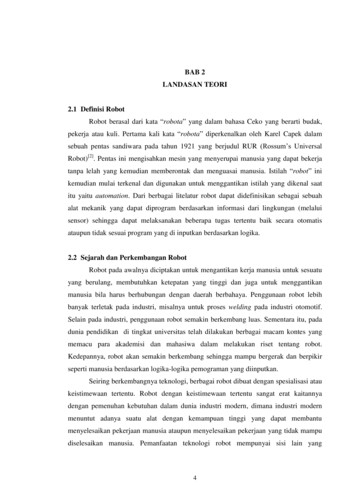
Robots may be supplied with optional accessories from the following list: 3.One or two light modules with three LEDs pointing in the same directions as the cameras.A Crowcon IR MAX or a Simtronics GD10-P00 sensor that detects hydrocarbon gases.A Falco 1.1 sensor that detects VOCs (volatile organic compounds – see Wikipedia).A Honeywell 3000 Mk II sensor that detects toxic gases.An Infrared Leak Detection Module which is built around a FLIR G300a camera.A hazard warning beacon. If fitted, the beacon will be permanently illuminated when therobot is away from the docking station.A power socket. This is supplied with a quick charger that can be plugged into the socket.Control StationsRobots can be controlled using PCs or smart phones (Apple or Samsung phones arerecommended). This guide describes the PC configuration which requires: 4.A laptop with a screen resolution of at least 1920 x 1080 and Google Chrome.A gamepad for driving the robot (Xbox is recommended).A mouse or trackpad for operating the cursor on the PC’s screen.Docking StationsThe robot automatically charges itself. At the end of a mission the operative should approachthe docking station in “slow speed” mode and in the direction indicated in the diagram below.Provided the robot is reasonably straight and central when approaching the docking station, therobot will automatically align the charging plates using the plastic strips under its hull.Once the front of the robot’s hull is pressing against the front of the docking station theoperative should stop driving forwards, activate the emergency stop switch on the controlscreen and deactivate the “Keep Awake” setting. The robot will automatically enter “In Dock”and “Charger Connected” status, and charge itself.When the robot is charging on the docking station it “sleeps” to conserve power and to reduce4G network charges. It takes 2 days to charge a fully-depleted battery. The battery level isreported every 18 minutes.ExRobotics B.V.ExR-1 RobotOperating GuideDocument No.:20190122IP1Version No.: 11Owner:Date:Ian Peerless2020-03-31Page 5 of 23This document is considered an uncontrolled copy when printed. Always ensure that you print and use a current version.Copyright 2020 ExRobotics B.V.
It’s best not to switch off the robot (using the black On/Off switch) when the robot is in thedocking station since this can disrupt charging. If this happens pull the robot 30cm back andswitch it off and on again.When a driver checks the “Keep Awake” setting the robot video streams will typically appearwithin 1 minute. The robot is then ready to use although it’s best to allow gas sensors 30minutes to warm up before starting a mission.When starting a mission and reversing away from the docking station, the driver shouldcarefully examine the back camera or the mirror on the front of the docking station (if fitted) toensure there are no obstructions.A power socket (when fitted) enables the robot to be charged within 3 hours. This requires therobot to be manually plugged into a power supply using a quick-charger that can be orderedwith the robot. The quick-charger’s lead is typically 3 meters long. If the robot is docked youshould first switch off power to the induction charger. When inserting the quick-charge plug,rotate the entire body clockwise before tightening the ring around its base. You can check thestatus of the charging using the LEDs and instructions on the quick charger.5.Cloud SoftwareRobots are operated and data is collected using the “cloud”. Access is granted as described inSection 7.2. Five types of screens are available as described below.5.1.Fleet Management and StatusFleet Management is the first screen that appears when users log on. It allows them to connectto any robot to which they’ve been granted access. Scrolling down reveals more robots.ExRobotics B.V.ExR-1 RobotOperating GuideDocument No.:20190122IP1Version No.: 11Owner:Date:Ian Peerless2020-03-31Page 6 of 23This document is considered an uncontrolled copy when printed. Always ensure that you print and use a current version.Copyright 2020 ExRobotics B.V.
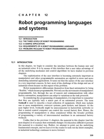
The Fleet Status screen (see below) is accessed by clicking on the “navigation menu” icon to thetop left of the fleet management screen.5.2.Robot ControlOnce a user has connected to a robot, most of the display information is intuitive: The major functions are summarised in the picture below.All three video streams are displayed on the control station. Usually the highest resolution,forward-facing inspection video will be in the largest window. Clicking on the “Expand”icon of any video stream window moves it to the largest window.To take a snapshot, hover the cursor over any video stream and then click on the “TakePhoto” icon that appears in the top-left corner. Then use the cursor to select the area ofinterest and click on the “Accept” button to capture the image.Snapshots are displayed in the “Event Log” once they have been uploaded to the server(this happens automatically after taking them) and can be viewed in large scale by clickingon them. From there they can be saved to the local machine by right clicking the full-sizedpicture and selecting “Save As.”.To take a video, a mission must be active. This is done by undocking the robot and drivingto the location of interest (Videos are currently not recorded if the robot status is “InDock”). Once ready, hover the cursor over any video stream and click on the “Video” icon(small circle) that appears in the top-left corner. The message “recording” will appear. Tostop recording click again the “Video” icon.Videos will be available only after the robot is back in the docking station (to savebandwidth when driving videos are not uploaded immediately). Videos are displayed in theMission Report website under “Recorded Media” and can be viewed in large scale byclicking on them. From there they can be saved to the local machine by right clicking thefull-sized picture and selecting “Save As.”.The icons at the top of the “Event Log” can be used to filter the time of the last eventse.g. images from the last 4 hours. Additionally, the “cloud download” icon to the right canbe used to download a complete set of recordings as a zip file.The audio stream of the microphone starts playing automatically and can be paused andre-started by clicking on the “Microphone” window.The screen shows the gas levels for those gas detectors that are fitted to the robot. Thegas alarm levels for the robot can be adjusted by clicking on the icon to the top right ofeach gas display window. An audio/visual alarm is emitted when the alarm level isexceeded.ExRobotics B.V.ExR-1 RobotOperating GuideDocument No.:20190122IP1Version No.: 11Owner:Date:Ian Peerless2020-03-31Page 7 of 23This document is considered an uncontrolled copy when printed. Always ensure that you print and use a current version.Copyright 2020 ExRobotics B.V.
The autonomy controls are grouped together:When the "Keep Awake” box is ticked the robot won’t sleep. If it’s unticked the robot willsave 4G costs and battery power by sleeping (whether or not it’s docked).Select a mission using the drop-down box. To launch the mission, click on the “Play”button to the left of the mission drop-down box, to cancel the mission press the buttonagain. Only launch a mission when an orange line is visible in the Floor Cam window (sothe robot can orientate itself) or when the robot is in a docking station.Using the cursor to activate the "Stop” button has the same effect as pressing theemergency stop switch on the gamepad. The drive motors are isolated until the switch isreleased. This is done using “Auto” or the green button on the gamepad.The gas detectors and lights controls are accessed by clicking on “More”.The top right of the screen shows the robot’s status. A tick adjacent to each itemindicates:o In Dock – robot is on the docking station.o Charger connected – the robot’s coil is connected to that in the docking station.o Charging – current is flowing into the battery pack.o E-Stop Released – the robot’s emergency stop has been released ready to drive.o Motors Enabled – the robot’s motors are not isolated anymore, so the robot can bedriven manually or autonomously (this takes a few seconds to change after checkingthe “Auto” box or pressing the green gamepad button).o Driving – the robot is in motion.o Gas Detectors On – The gas detectors are powered up (they have individual warm-uptimes and only after this time the gas displays will start showing measurementvalues).o Manual Control – the robot is being controlled from this control station by a driver.Hovering over an icon or text will often provide more information.Drivers can change the robot location on the screen by clicking on the “Site Config” optionin the navigation menu to the top left of the screen. They can report issues to ourengineers using the “Feedback” option in the user menu to the top right of the screen.ExRobotics B.V.ExR-1 RobotOperating GuideDocument No.:20190122IP1Version No.: 11Owner:Date:Ian Peerless2020-03-31Page 8 of 23This document is considered an uncontrolled copy when printed. Always ensure that you print and use a current version.Copyright 2020 ExRobotics B.V.
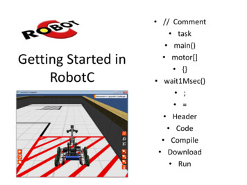
The gamepad controls are illustrated below:The green button activates remote control by enabling the gamepad and drive motors.The blue button switches from remote control to autonomous driving.The yellow button deactivates remote control by disabling the gamepad.The red button on the gamepad stops the robot and isolates the motors, identical to the“Stop” icon. The analogue joysticks are used to drive (left stick) and steer (right stick) the robot. Holding down the LB/RB buttons changes speed mode (slowest - no buttons pressed,fastest - both buttons pressed).When in autonomous mode, the robot will stop if the connection to the driver’s control station isbroken for more than 5 seconds. This means that an active control station is required for therobot to be operational in autonomous mode. The robot will also stop if it loses sight of theorange line. In this situation an audio/visual alarm will be triggered on the robot control screen. 5.3.Mission EditorThis screen enables planners to construct and edit autonomous missions.A robot mission is typically a circuit following an orange line that starts and finishes at a dockingstation. During the circuit the robot will perform actions for points of interest when the robot islocated at a waypoint: A typical action is to record a video, snapshot, sound, or sensor reading.Actions are targeted at points of interest (POIs). This is a 3D location at which theappropriate camera or sensor is targeted. Examples of POIs are valves, flanges andpumps. To target the POI the robot will usually need to change its azimuth (rotate) and insome cases will require a camera to lift its field of view (elevate). There can be more thanone action at a POI.Waypoints are 2D locations from which POIs are observed. There can be multiple POIs ata waypoint. Waypoints are defined by an array of chili-tags (see Section 7.5).There can be multiple waypoints on a mission.ExRobotics B.V.ExR-1 RobotOperating GuideDocument No.:20190122IP1Version No.: 11Owner:Date:Ian Peerless2020-03-31Page 9 of 23This document is considered an uncontrolled copy when printed. Always ensure that you print and use a current version.Copyright 2020 ExRobotics B.V.
A planner will:1. Define the exit direction of the robot when leaving the docking station. When the robot“undocks” it drives in reverse until the middle point between the “Dock 1” and the “12:00”tags. Then the robot will rotate and exit the docking station to start following the line inone of three possible directions: 03:00 (robot rotates 90 degrees clockwise), 06:00 (robotrotates 180 degrees), or 09:00 (robot rotates 90 degrees counter-clockwise).o From the Mission Editor screen select action “Undocking”o Select the Exit Direction (e.g. 09:00)o Write a name in Select Action Name e.g. “Undock”o Click “Save”2. Launch an autonomous mission from the Robot Control screen and stop the mission a fewmeters before the waypoint at which actions are to be performed (with the orange linevisible from the floor cam).3. Open the Mission Editor screen.4. Press the play button. The robot will drive to the POI tag and then stop between the POIand 12:00 tags.5. Enter the waypoint number (the number on the chili-tag).6. Rotate the robot (and elevate the camera) using the left/right icons on the mission editoruntil the sensor is pointing at the POI.7. Tick the action to be performed.8. Frame any image using drag and drop and then take the picture.9. Click “save” and give the action a recognisable name (e.g. equipment TAG number).10. Repeat these steps for all actions that might be required at that waypoint.11. Use the left/right icons to point the robot at the 12:00 tag.12. Open the Robot Control screen and relaunch the autonomous mission.ExRobotics B.V.ExR-1 RobotOperating GuideDocument No.:20190122IP1Version No.: 11Owner:Date:Ian Peerless2020-03-31Page 10 of 23This document is considered an uncontrolled copy when printed. Always ensure that you print and use a current version.Copyright 2020 ExRobotics B.V.
Waypoints can also be used at junctions where a robot can select between alternative routes orcan return the way it’s come.1.2.3.4.5.From the Mission Editor screen select action “Junction”Select Exit Direction (e.g. 06:00)Select the waypoint number for the Junction (the number on the chili-tag).Give the action a name e.g. “Junction 1”Click “Save”All inspection actions (e.g. Photo) can also be defined and executed at junction waypoints. Forthis you just need to add the actions that you require to the waypoint number as describedpreviously and then add a “Junction” action to the same waypoint number.Actions are listed by waypoint in the right-hand column of the mission editor. Planners cancreate missions by ticking the actions to be performed and saving the mission using arecognisable name.When a mission is to be performed, select and launch the mission from the Robot Controlscreen (see Section 5.2). Actions will be recorded in the mission report.5.4.Mission ReportA typical mission report screen is as follows.The data for a mission is displayed by clicking on the relevant block to the left of the screen. The gas detector values are displayed on the adjacent graphs.The plan will be green where the gas levels were below the lower alarm level, amberwhere they were between the two alarm levels, and red where they were above the upperalarm level. Section 5.2 describes how to set the alarm levels.Other information that has been gathered at Waypoints is displayed in the right-hand partof the screen.Snapshots and gas readings are uploaded immediately. Other recordings are uploadedwhen the robot returns to its docking station. Video and sound recordings are limited to 2minutes for each action.To study a chart in more detail: Hover the cursor over a point on the chart to get a digital reading.Zoom in with the mouse wheel or by left-clicking and dragging.Pan by using the shift key, left-clicking and dragging.Return to the default view by double clicking.ExRobotics B.V.ExR-1 RobotOperating GuideDocument No.:20190122IP1Version No.: 11Owner:Date:Ian Peerless2020-03-31Page 11 of 23This document is considered an uncontrolled copy when printed. Always ensure that you print and use a current version.Copyright 2020 ExRobotics B.V.
6.Operative TrainingExperienced operatives will explain the safety items in the ExR-1 Robot Operating Instructionsand Guide to new operatives and key site personnel. They’ll also show new operatives how touse the control station.In particular they should emphasise the importance of careful driving: Impact damage to facilities, people and the robot can be avoided by careful driving.Always check the surroundings using all three cameras before enabling the drive motors.Test the controls after leaving the docking station and before commencing a mission.Approach hazards such as ledges, sumps, ramps, overhead obstructions and the dockingstation with the speed set in “slow” mode. Allow for communications latency.Don’t spot turn on grass/mud/anti-slip gratings/gravel and don’t spot turn in high speedmode. These actions might cause a track to “freeze”. (spot turns are when you drive therobot left or right with no forwards or backwards motion).The robot isn’t designed to climb stairs or gradients above 30 degrees. It may topple over.It can however cross steps up to 20cm high. Approach them perpendicularly.The downward facing camera can enable precise positioning.The warranty doesn’t cover impact damage.The robot must be returned to the docking station at the end of a mission and before thebattery is fully discharged. If the battery charge reaches 0% the robot will shut-downwhich will require a visit to the site and robot recovery to the docking station. This willalso invalidate the battery warranty.To prevent over-heating the robot monitors the average current being drawn from thebattery. If it’s too high a warning will be displayed on the control station. The drivershould stop the robot and wait 15 minutes for the batteries to cool before recommencingthe mission. If the driver does not act, or the current is too high, the drive motors will beisolated for 15 minutes. If this happens the robot should be returned to the dockingstation and ExRobotics consulted before another mission is launched (see Section 8.1).The robot is designed to prevent unsafe driving so in some situations it will autoimmobilise itself e.g. when voltage is applied to the power socket or when the keep awakebox has not been checked.New operatives should not drive the robot alone until they’ve demonstrated they understandthese items and that they can safely navigate the robot around typical routes.7.Deployment7.1.PreparationsThe robot order will specify: The operating conditions for the robot (temperature range, equipment protection level,explosion group, temperature class, and ingress protection).The accessories that are to be installed on the robot.The type of sensor that is to be installed in the Honeywell gas detector (if fitted).Whether the customer or ExRobotics will supply the 4G SIM card for the robot. The SIMneeds to be delivered to ExRobotics’ Delft facility before the robot is assembled.Before a robot is delivered, ExRobotics will verify that the robot is suitable for the deploymentlocation and will agree a position for the docking station with the customer. The customer willalso complete any MOC (management of change) and/or risk assessments they might require.ExRobotics B.V.ExR-1 RobotOperating GuideDocument No.:20190122IP1Version No.: 11Owner:Date:Ian Peerless2020-03-31Page 12 of 23This document is considered an uncontrolled copy when printed. Always ensure that you print and use a current version.Copyright 2020 ExRobotics B.V.
Key issues when verifying a robot is suitable for a location are: The robot will not be exposed to conditions out-with the validity of its Ex certificates.There are navigable routes without excessive steps, narrow gaps, and low overhangs.The routes enable the robot to perform the necessary inspections.There’s a good 4G signal wherever the robot must be remotely controlled. This will betested with the type of SIM card that’s to be installed in the robot. Ideally the total latencybetween the control station and robot should be less than 250 ms and the uploadbandwidth should be at least 5 MBit/s.The docking station is 100.5cm long, 70.2cm wide and 20cm high (55cm high with a robotinstalled). It will: Have access to a 110/120V or 220V/240V AC power supply.Be located in a safe zone – it isn’t certified for potentially explosive environments.Be on a hard surface (not gravel or grass) that’s essentially horizontal.Allow the robot to approach the docking station in a straight line for at least 3 meters (thishelps with alignment).Have the strongest practical 4G signal – it’s especially important that the robot has astrong signal before and after a mission.Be sheltered from climactic extremes (e.g. direct sunlight in the tropics, prevailing windsand snow in arctic environments).The customer will secure the docking station to the ground using the holes in each corner of thedocking station. Unless a specific power lead has been requested, they will also connect thedocking station to the power supply using the connections pictured below.The docking station includes two dome headed bolts that press against the front of the robot’shull to ensure it’s docked in the correct position. They’re u
An Infrared Leak Detection Module which is built around a FLIR G300a camera. A hazard warning beacon. If fitted, the beacon will be permanently illuminated when the robot is away from the docking station. . Robots are operated and data is collected using the "cloud". Access is granted as described in Section 7.2. Five types of screens are .