Transcription
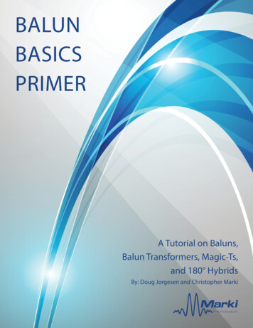
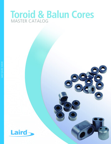
Toroid&BalunCoresMASTER CATALOGwww.laird.com1
ABOUT LAIRD TECHNOLOGIESLaird Technologies designs and manufactures customized, performancecritical products for wireless and other advanced electronics applications.The company is a global market leader in the design and supply ofelectromagnetic interference (EMI) shielding, thermal management products,mechanical actuation systems, signal integrity components, and wirelessantennae solutions, as well as radio frequency (RF) modules and systems.Laird Technologies is the world leader in the design and manufacture ofcustomized, performance-critical products for wireless and other advancedelectronics applications. Laird Technologies partners with its customers tocustomize product solutions for applications in many industries including: Network Equipment Handsets Telecommunications Data Transfer & Information Technology Computers Automotive Electronics Aerospace Defense Medical Equipment Consumer Electronics IndustrialLaird Technologies offers its customers unique product solutions, dedication toresearch and development, as well as a seamless network of manufacturingand customer support facilities across the globe.2www.lairdtech.com
TABLE OF CONTENTSQUALITY ASSURANCE . 4Quality Philosophy . 4Quality Testing . 4Quality Measurement System . 4PART IDENTIFICATION . 5Part Numbers . 5STANDARD COMPONENTS . 6Toroidal Core Coatings . 6LAIRD TECHNOLOGIES FERRITE CORE MATERIALS . 7Common Mode Materials . 7Comparing Common Mode Materials . 8Low Frequency Material 35 . 9Mid Frequency Material 28 . 10High Frequency Material 25 . 11DC Bias Materials . 12Comparing DC Bias Materials . 13DC Bias Standard Temperature (0 to 70 C) Material 36 . 14DC Bias Extended Temperature (-40 to 85 C) Material 46 . 15High DC Bias Extended Temperature (-40 to 85 C) Material 66 . 16Material 36/46 Minimum Inductance with Various Turns (8 mA DC Bias) . 17Material 66 Minimum Inductance with Various Turns (16mA to 32mA DC Bias) . 19High Permeability Materials for Telecom . 23Comparing Telecom Materials . 24Telecom High Permeability Material 40 . 25Material 35 . 26MATERIAL COMPARISON CHART . 28CATALOG TOROID PARTS . 29MEDIUM & LARGE CATALOG TOROID PARTS . 33BALUN CORE CATALOG PARTS . 34FERRITE PROPERTY MEASUREMENT . 35Initial Permeability, Losses & Inductance Factor . 35Changes in Inductance versus Temperature & Curie Temperature. 35Flux Density, Residual Flux Density, Coercive Force & Amplitude Permeability . 36Pulse Characteristics . 37Power Loss . 37Measurement of Impedance Of Ferrite Component . 38TERMINOLOGY. 39NOTICELaird's products or subcomponents are not specifically designed or tested by Laird for use in any medical applications, surgical applications, medicaldevice manufacturing, or any similar procedure or process requiring approval, testing, or certification by the United States food and drugadministration or other similar Governmental entity. Applications with unusual environmental requirements such as military, medical, life-support orLife-sustaining equipment are specifically not recommended without additional testing for such application.wwwwww.laird.com3
QuALITy ASSuRANCEQuALITy PHILOSOPHyCustomer focus is paramount in our quality program. Our quality philosophy is outlined as follows:Laird Technologies is a company committed to continuous improvement. We fulfill this commitment by continually improvingthe quality of the products and services we provide our customers, both external and internal.We recognize that our customers define quality. We further recognize that continuous improvement can only result from thefullest development of our people and technologies.We believe that to pursue this course, we must set unselfish service as our standard for conduct. Building on the values ofour history, we will raise our standards of performance through continuous improvement and imagination. In addition, ouractions must demonstrate integrity, honesty, excellence and self-discipline.We believe in teamwork. Our commitment to continuous improvement is fulfilled and maintained by the combined, cohesiveefforts of people with a common goal.QuALITy mEASuREmENT SySTEmLaird Technologies’ Quality Management Systems have been certified to the ISO 9001:2000 requirements by CeramicIndustry Certification Scheme Ltd.QuALITy TESTINGWe test on the following equipment:Inductance, Loss Factor: Hewlett-Packard 4274A Multi-Frequency LCR MeterHewlett-Packard 4275A Multi-Frequency LCR MeterHewlett-Packard 4284A Multi-Frequency LCR MeterImpedance:Hewlett-Packard 4396B Network/Spectrum AnalyzerHewlett-Packard 4991A Network/Spectrum Analyzer4www.lairdtech.comwww.laird.comwww
PART IDENTIFICATIONPRODUCT TYPES35 T -PART NUMBERSPart numbers use a ten character alphanumericnomenclature providing: The material designation The product type (shape) A basic size descriptionTransformer and Filter Core Division uses two basicshape designators:T for toroidal coresExample: 35T0100-00PN for balun coresExample: 35N0136-00PPART NUMBERING SYSTEM EXAMPLE35T0100-0Material Product Part SizePartTypeCodeCode Thickness0PCatalogParyleneCoatingMATERIAL DESIGNATOR35 -A two digit material designator is assigned to materials on thebasis of initial 025125364500464000663200High Permfor Telecom40*10000High Permeability forResonant Wireless ChargingRP250Low power loss material653300Typical ApplicationCommon ModeFilteringDC Bias EthernetTransformersBASIC SIZE DESCRIPTION35 T 0100 -The four digits following the product description provide thelargest dimension of the part in thousandths of an inch. Fortoroids and similar shapes, it usually describes the outside ormajor diameter of the core.the part’s description.PARTS MODIFIER SERIES35 T 0100 - 00Pthickness. A zero through nine digit refers variations in thicknessfrom the same tool. The second modifying digit relates to aCOATING DESIGNATIONSP — ParyleneHi-Pot Rating 1000 VAC minimumNominal Thickness: 0.0005” / 0.0127 mmH — EpoxyHi-Pot Rating 1000 VAC minimumNominal Thickness: 0.003” / 0.0762 mm* 40 material large toroids are mostly used for very low frequencypower supply wwwwww.laird.com5
STANDARD COmPONENTSSoft ferriteTypical Physical ConstantsSpecific Heat0.25 cal/g/ CThermal Conductivity10-2 cal/sec/cm/ CCoefficient of Linear Expansion8-10 x 10-6/ CTensile Strength500 kg/cm2Compressive Strength4200 kg/cm2Youngs Modulus1260 kg/cm2Hardness (Knoop)650Density4.6 to 4.9 g/cm3mechanical TolerancesOD-ID Tolerancesmm (inches)OD - IDuncoated Tolerance 5.05 (.199).127 (.005)5.08 (.200) - 9.50 (.374).152 (.006)9.53 (.375) - 15.85 (.624).254 (.010)15.88 (.625) - 25.37 (.999).381 (.015) 25.40 (1.000).508 (.020)HT TolerancesHTuncoated Tolerance 6.32 (.249).127 (.005)6.35 (.250) - 7.34 (.289).178 (.007) 7.37 (.290).254 (.010)TOROIDAL CORE COATINGSIf required by customer applications, smooth, resistive coatings may be provided. Standard dimensions foreach toroid are listed in the parts chart, and coating will alter these. Inductance values are as shown forstandard sizes and cores are checked after coating to ensure compliance.PARyLENEParylene is ideally suited for core sizes with outside diameters less than 9.5 mm (0.375”). Parylene is ahighly conformal coating with uniform thickness even around corners and edges. It is applied by vapordeposition, which prevents clogging of small openings. The addition of Parylene results in very little increasein core size. It has a high resistivity and a low coefficient of friction (close to that of Teflon), which results inlow wire insulation abrasion during winding. Parylene’s relatively low dielectric constant is 2.95, resultingin only a small increase of winding-to-core capacitance. After coating, cores are Hi-Pot tested to 1000 VACvolts for single thickness. Higher voltages available upon request via additional coating thicknesses.EPOxyEpoxy coating is the choice for cores about 9.5mm (0.375”) diameter or larger. It is applied by spraying.Because of its thickness, epoxy coating provides some cushioning during winding. Epoxy coating providesinherent toughness, corrosion resistance, and very good adhesion. These properties are retained even afterlong term heat aging. After coating, cores are Hi-Pot tested to 1000 VAC.6www.lairdtech.comwww.laird.com
COMMON MODE MATERIALS - 35, 28, 50125% 20 20 30Gauss450032503600TYPICAL VALUESPARAMETERSYMBOLRelative Initial PermeabilityµiUNITAL ToleranceSaturation Flux DensityBSat Field IntensityHResidual Flux DensityBrCoercive ForceHCRelative Loss Factorat Frequencytan δfCurie m8312710MHz200.10910.107400.10 C 150 175 sity-6Impedance with 10 TurnsNominal ValuesPart NumberLow Frequency35 Material@ 10 MHzMid Frequency28 Material@ 150 MHzHigh Frequency25 Material@ 300 4EFFECT OF TURNS ON IMPEDANCEIdeally, impedance would be proportional to frequency and the square of the number of turns regardless of themagnitude of either. This is generally the case at very low frequencies, but becomes less valid as frequency increases.The predominant cause of such behavior is interwinding capacitance. Capacitance is directly proportional to the area ofthe conductor and inversely proportional to the distance between the conductors. As the number of turns increases, thearea of the conductor (the length of the wire) increases and the distance between the conductors (the spacing betweenturns) decreases. The end result is an LC resonance above which capacitive reactance decreases impedance. The numberof turns, their spacing, and the uniformity of their spacing are major factors in the frequency response of wound toroidal.7www.lairdtech.comwwwwww.laird.com7
COMPARING MATERIALST0155-10P @ 10 Turns"Core Size 3.94 (O.D.) x 2.24 (I.D.) x 1.27 (H.T.)"150012502528100035PERFORMANCE OF DIFFERING PERMEABILITY COMMONMODE MATERIALSImpedance cores are used to suppress unintended signals on or being emittedfrom cables or wires. If these signals are not accounted for, they can interferewith electronics and/or cause a failure to meet government emissionsstandards or susceptibility regulations. The cores suppress unintended signalsZ (Ω) 750500around that conductor. A ferrite core, if placed around the conductor, can250magnitude of the unintended signal.0110100f (MH z)The impedance (Z) that weakens the unintended signal, consists of twoT0155-10P @ 30 Turns"Core Size 3.94 (O.D.) x 2.24 (I.D.) x 1.27 (H.T.)"10000sum of the squares of the resistance and reactance, or Z (R2 X2), whichis measured in ohms.358000inductance that exists in the core as a function of frequency. In other words,X 2 * p * frequency * inductance (L). The second is a resistive component(R). It results from the core’s natural tendency to resist an electrical signal, in286000Z (Ω)254000Laird Technologies low frequency cores have high permeability, resulting insuppression of low frequency signals. As demonstrated in the following chart,the impedance at very low frequencies is principally contributed by the X. Athigher frequencies the R predominates.20000110100f (MH z)T0100-10P @ 10 Turns"Core Size 2.54 (O.D.) x 1.27 (I.D.) x 1.27 (H.T.)"150035T0155-00P @ 10 TurnsZ, R, X vs. Frequency100012507501000Z (Ω) 500Z (Ω) 750Z28R500250X25000110100f (MH z)88www.lairdtech.comwww.laird.comwww0.1110f (MH z)100
mATERIAL 35COMMON MODE LOW FREQUENCY5000 PERmEABILITyInitial Permeability vs. TemperaturePermeability & Loss Factor vs. 010Lo s s F a ctor310-5200010 20.0010-5005010015020010 -60.011f (MH z)T ( C)Comparing Turns - 35T0155-10P100.1Saturation Flux Density vs. Temperature450030 tu rn s4001010 tu rn s3300B(mT )Z ( Ω) 10 22001 tur n10 11000-5010 0110100-250255075100125150175T ( C)f (MH z)9www.lairdtech.comwwwwww.laird.com9
mATERIAL 28COMMON MODE MID FREQUENCY850 PERmEABILITyInitial Permeability vs. TemperaturePermeability vs. -2502550751001251501752000.010.1110f (MH z)T ( C)Comparing Turns - 28T0155-10PSaturation Flux Density vs. Temperature10 440030 tu rn s10330010 tu rn sZ ( Ω)10B(m T )210 11 turn10 0100011020010f (MH 0T ( C)75100125150
mATERIAL 25COMMON MODE HIGH FREQUENCY125 PERmEABILITyInitial Permeability vs. TemperaturePermeability vs. 0 -25025507 5 100 125 150 175 200 225 250 2750. 1110100f (MH z)T ( C)Comparing Turns - 25T0155-10PSaturation Flux Denasity vs. Temperature10 450030 tu rn s10400310 tu rn s300Z ( Ω)102B(m T )2001 tur n10 110010 0110100f (MH z)0-50050100150T ( C)11www.lairdtech.comwwwwww.laird.com11
DC BIAS MATERIALS 36, 46, 66TYPICAL VALUESDC BIAS MATERIALSPARAMETERSYMBOLRelative Initial PermeabilityµiAL ToleranceSaturation Flux DensityBSat Field IntensityHResidual Flux DensityBr36DC BiasStandard Temp46DC BiasExtended Temp66High DC BiasExtended Temp450040003200% 25 25 0.100.125A/m8810Coercive ForceHCRelative Loss Factorat Frequencytan d m if10MHz100.10100.1020.10Curie TemperatureTC C 150 150 tyMinimumALValues(nH/T2)DC Bias Standard TempMaterial 36ALTargetAL .35 Oe Bias Min2DC Bias Extended TempMaterial 46ALTargetAL .35 Oe Bias MinPartNumbers25 C25 C0 C to70 C25 C25 C-40 C to80 omwww
COMPARING MATERIALS25 C Minimum Permeability500025 C mi nimu 00.25300.38DC Bias,400.5050Am0.63Oe-1H0 C to 70 C Minimum Permeability50000 - 70 C mi nimu .25300.38DC Bias,40500.500.63Oe50Am0.63OeAm-1H-40 C to 85 C Minimum Permeability5000450040003500µ 300025004620001500100000100.13200.25300.38DC Bias , H13www.lairdtech.comwwwwww.laird.com400.50-113
mATERIAL 36DC BIAS STANDARD TEMPERATURE(0 C TO 70 C)4,500 PERmEABILITyAmplitude Permeability vs. Flux DensityInitial Permeability vs. Temperature80001000070008000600025 5075100125150017550100150200250300350400B(mT )T ( C)Incremental Permeability vs. Field IntensityPermeability & Loss Factor vs. Frequency10100005000-1450010 -2800040000 C35006000µ 30002500µ'µ', µ''25 C-40 C10 -3Lo s s F a ctorLF400070 C10-410-510-6200085 Cµ"20001500100000100.13200.25300.38DC Bias,H400.50500.63AmOe-100.1110f (MH z)1614www.lairdtech.comwww.laird.comwww
mATERIAL 46DC BIAS EXTENDED TEMPERATURE(-40 C TO 85 C)4,000 PERmEABILITyInitial Permeability vs. TemperatureAmplitude Permeability vs. Flux Density10000800070008000600050006000µµia400025 0100150200250300350400B(mT )T ( C)Permeability & Loss Factor vs. FrequencyIncremental Permeability vs. Field Intensity10100005000-145004000800010 -26000103500µ 300025 C-40 CLo s s F a ctorµ', µ''2500-3LFµ'400010-410-510-60 C200070 Cµ"200085 C1500100000100.13203040500.250.380.500.63DC Bias , H15www.lairdtech.comwwwwww.laird.comAmOe-100.1110f (MH z)15
2500μi 2000μemATERIAL 661000HIGH DC BIAS EXTENDED500 TEMPERATUREPoE/PoE APPLICATION 0-40 0 40 80 120 160 200(-40 C TO 85 C)Temp ( )1500Initial Permeability vs 00300030003000250025006000250025002000μiµi 20002000μ' μ',μ"μ'' 002000002540405 0 80 7 510012080T ( C)120( C)040003500μe125160 002500100010002000μ',μ" DC-Bias H ( Oe)0.1110Freq(MHz)16μ'μ"0.80.8DC-Bias H (Oe)500encyμ'2000μe 001100 1 freq (mHz) 100.0 Freq(MHz)0.20.41001000.6DC-Bias H ( Oe)-40300030004000μ'5000.1Premeability vs Frequency25μ'μ''1000Incremental Permeability vs. Field Intensity3500350000.01500Temp ( )400040005003000Incremental Permeability vs. Field Intensityure1000Permeability vs Frequency0-25 01500Premeability vs FrequencyInitial Permeability vs. Temperature000-50-40-402000Incremental Permeability vs. Field Intensity3,200 PERmEABILITy400025001000.81.0
mATERIALS 36/46MINIMUM INDUCTANCE WITH VARIOUS TURNS(8 mA DC 60.350.320.320.320.320.320.350.320.300.3025 C89295183249381195-259150243102210180109-18336516 turns360-70 C73245151206316161-2141242018417314990-15130225 C125418270367546290-384226366154316271162-27555120 turns360-70 C105348224304453240-318187303127262224134-22845525 C147489356484700392-509303491206424364215-37775424 turns360-70 C122407297403585326-423252407171352302179-31262525 C-291177240372187214249143232----350---46-40-85 0.240.220.2225 C-427267362551284323378219355----532---46-40-85 0.290.270.2725 C-555364494741394441517303490----740---46-40-85 0.350.320.3225 C106355226307467242-321186301126260223136-22845618 turns360-70 C88295187254387200-266152249104215184112-18837725 C-356220299461234267311179290----438---46-40-85 C-248155211323166188220127206----310---25 C140466314426628339-447265429180370318189-32765522 turns360-70 C117389261354524281-371219355149307263157-27154225 C-493315428646337381446260422----636---46-40-85 C-338219297445235265311183296----446---25 C160533397539725440-568346560235484415244-43086126 turns360-70 C131436333451603366-475287466195402345203-35771525 C-622413560823449500587349565----844---46-40-85 tech.comwwwwww.laird.com
mATERIALS 36/46MINIMUM INDUCTANCE WITH VARIOUS TURNS(8 mA DC 50.520.470.470.470.470.470.520.480.450.4525 C--442599826504-651410665279574492275-530106130 turns360-70 C--365496665420-541343555233480411228-44388525 C--465631-528-689437708297612524291-565113032 turns360-70 C--379514-437-567364589247509437239-47294425 C-----586-739484784329678581312-616123236 turns360-70 tech.comwww.laird.comwww28 turns25 C--506687994556612732435704----1062---46-40-85 370.350.3525 C--5497441051605664796481780----1160---46-40-85 450.420.4225 C--623846-705740909565915----1358---46-40-85 0.470.473625 0-70 C133443348472639405-507319516217446382221-39779525 C-674460625911503557656392636----959----40-85 C-398314427592345381448270438----661---25 C--483656-567-718454736309636545303-597119434 turns360-70 C--386525-464-582376608255526451246-49799425 C--588798-662712855520843----1271---46-40-85 C--348472-430421529353572----862---25 C--------497805338696597--653130538 turns360-70 C--------400648272560480--534106925 C-----744-956598969----1436---46-40-85 C-----423-520360584----849---
mATERIALS 66MINIMUM INDUCTANCE WITH VARIOUS TURNS20 turns (25 6546122 turns (25 C)22 turns (0-70 524622930340460644040356746320 turns (-40- 85 827125432944065946441959048220 turns (0-70 4435527825434546469551046865953822 turns (-40- 85 dtech.comwwwwww.laird.com
mATERIALS 66MINIMUM INDUCTANCE WITH VARIOUS TURNS24 turns (25 1572658632mA--------50048468255026 turns (25 C)26 turns (0-70 330327737951677358253475261424 turns (-40- 85 935432943658287363358081766724 turns (0-70 2829541256384365460685369726 turns (-40- 85 76
mATERIALS 66MINIMUM INDUCTANCE WITH VARIOUS TURNS28 turns (25 4076062130 turns (25 C)30 turns (0-70 4260490571867294677328 turns (-40- 85 74233875287191077799739104185028 turns (0-70 -466639958777737103883930 turns (-40- 85 irdtech.comwwwwww.laird.com
mATERIALS 66MINIMUM INDUCTANCE WITH VARIOUS TURNS32 turns (25 -61486570732mA-------------32 turns (-40- 85 560983112469719011269103732 turns (0-70 9
Hewlett-Packard 4275A Multi-Frequency LCR Meter Hewlett-Packard 4284A Multi-Frequency LCR Meter Impedance: Hewlett-Packard 4396B Network/Spectrum Analyzer Hewlett-Packard 4991A Network/Spectrum Analyzer. wwwwww.laird.com. www.lairdtech.com. 5 5. www.lairdtech.com. PART IDENTIFICATION.
