Transcription
ROM-DK3420 ARM Starter KitQuick Starter Guide
Copyright NoticeThis document is copyrighted, 2016 by Advantech Co., Ltd. All rights are reserved.Advantech Co., Ltd. reserves the right to make improvements to the products described in thisdocument at any time. Specifications are thus subject to change without notice.No part of this document may be reproduced, copied, translated, or transmitted in any form or byany means without the prior written permission of Advantech Co., Ltd. Information provided inthis manual is intended to be accurate and reliable. However, Advantech Co., Ltd. assumes noresponsibility for its use, or for any infringements upon the rights of third parties which may resultfrom its use.All the trademarks of products and companies mentioned in this document belong to theirrespective owners.IntroductionAdvantech ARM-based Starter Kits provide a shortcut for ARM platform evaluation anddevelopment. The kit includes key elements of a development environment including main boardswith high performance CPU, cables, adapter cards, LCD panel and power adapter. The AdvantechARM Starter Kit is designed to give you more time to concentrate on your own product innovationand make the whole process faster, easier and less stressful.The Advantech ARM Starter Kit was released along with a built-in OS image in Linux which allowsusers start their evaluation immediately after they open the box. Other OS such as Android, YoctoLinux and Ubuntu are also available for different applications; each carefully verified for onlinedownload. The source codes of these supported OS are all open and available for users to helpdevelop application code easier. In addition, Advantech offers tools for application developmentincluding Qt, a cross-platform tool for device creation, UI and application development, andAdvantech WISE-PaSS/RMM APIs for device access, control and monitoring. All add-on softwareofferings are totally verified and 100% free of charge. Advantech is committed to offering theembedded community the best, most compact and reliable development platform for ARM-basedsolution development.
1. Board OverviewROM-3420ROM-DB3900
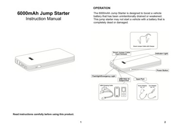
2. Packing List1700001524US Power Cord1700004711SATA Cable1700006911USB OTG to Type A Cable1700019077-11USB OTG Cable1700019474Debug port to PC Cable1700021882-01LVDS Backlight Cable1700021883-01LVDS Cable1700021941-01SATA Power Cable1700022373-01Debug Port Cable1700022840-01SPDIF Cable (Reserved)1701100300COM Cable1930004835Screw M2.5x12.3L F/S D 5 H 0.8 (1 ) ST Ni1935020402Screw M2.5x4L R/S D 4.5 H 1.7 (1 ) ST Ni1960065189N001Heatsink9680015491Mini-PCIe to PCIe adapter card9696ED2000EROM-ED20 Debug Port Adapter Board9696M34200EROM-3420 Dual Core 1GHz 0 60 9696M39000EROM-DB3900 RTX 2.0 Carrier Board 0 60 9696MEG510EROM-EG51 CODEC Board9696MX5300ESYSTEM BUS to UART Adapter Board96LEDK-A070WV40NB17" LED PANEL 400N 800X480 Resolution96PSA-A90W19V1-1Adapter 100-240V 90W 19VSQF-ISDS1-4G-82CSDHC Class 10 4GB SD Card (0 70 C)3. Board introduction PART A
PART B PART C
4. ScrewsThere are 3 different types of screws in this Starter Kit, they are designed for different purpose5. Board Assembly5.1 Assemble ROM-3420 to its carrier board ROM-DB3900①Assemble module to carrier board②Fix the screws properly
5.2 Assemble 9696MX5300E to carrier board ROM-DB3900①Assemble 9696MX5300E to carrier board②Push Down
5.3 Assemble ROM-EG51 CODEC Board to carrier board ROM-DB3900①Take out ROM-EG51 CODEC Board②Assemble ROM-EG51 CODEC Board to ROM-DB39005.4 Assemble 9680015491 PCIe to miniPCIe board to carrier board ROM-DB3900①Take out 9680015491 PCIe to miniPCIe board
② Insert mini-PCIe card if needed. Mini-PCIe card is optional peripheral which is not included in thepackage of ROM-3420 Starter Kit③ Fix the screws of mini-PCIe card④ Insert the adapter card to ROM-DB3900
⑤ Connect USB Cable if your mini-PCIe card needs USB signalUse this Cable pulls USB signalto 9680015491 PCIe to miniPCIeadapter board
6. Cable Assembly6.1 COM Port Cable① Cable overview② Connect COM Port cable to Carrier board COM0 COM46.2 SATA Cable① SATA Cable Overview
② Connect SATA cable and SATA Power Cable6.3 LVDS Cable① LVDS Cable Overview② Connect LVDS cable and Backlight Cable to ROM-DB3900③ Adjust the Backlight Jumper. Default is 5V but the Panel 96LEDK-A070WV40NB1 is 12V.
④ Connect to 96LEDK-A070WV40NB1
7. Other Peripheral Assembly7.1 SD Card insertion① You need to refresh the onboard e.MMC image through SD card, please insert SD card to SD slot asindicated in below photos.7.2 Heat Spreader Assembly① ROM-3420 Heat Spreader② Peel off the protection film in the back
③ Assemble Heat Spreader to ROM-3420④ Fix Screws
8. Debug Port Connection① Connect debug port cable to debug port adapter board, make sure the jumpers are set as below:② Connect debug port to ROM-3420③ Connect debug adapter board to a COM port cable④ Connect COM cable to PC
④Set hyper terminal in your PC as below
9. ROM-3420 Jumper/Switch Setting
10. Carrier Board Jumper SettingPlease adjust the jumpers before starting evaluation
11. Software Functionality
For more SW/Tool, please refer loadfile1/1-Y0QMII/ROM-3420 User Manual Ed.2-FINAL.pdf
1700006911 USB OTG to Type A Cable 1700019077-11 USB OTG Cable 1700019474 Debug port to PC Cable 1700021882-01 LVDS Backlight Cable . ③ Connect debug adapter board to a COM port cable ④ Connect COM cable to PC . ④Set hyper terminal in your PC as below . 9. ROM-3420 Jumper/Switch Setting . 10. Carrier Board Jumper Setting