Transcription
Electrical Area Classification 101An Introduction to AreaClassification the BasicsIEEE Houston CEDOctober 3rd, 2017
Vincent W. Wedelich, PE, MBA Project ManagerAssociate Electrical Engineer10 Years Consulting at BMcD16 years in manufacturingEAC Projects, Refineries,Chemical Facilities, DesigningSkids etc.
Safety Topic Active ShooterLast resort is to fight.
What will be covered in this course.Introduction to area classification terminology andstandards. Identifying electrical equipment that can be usedin different hazardous areas. Introduction to PIP ELEHA01 Specification Introduction to PIP ELEHA01 Form No. 1Flammable Combustible. Introduction to PIP ELEHA01 Form No. 2 Sourcesof Release.
WHAT WE TYPICALLY USE IN THE USA:API-500, NFPA 70, NFPA 496, NFPA 497
HISTORY OF STANDARDS Originally published in 1955 American Petroleum Institute (API) RecommendedPractice 500A concerns the classification of locations for electrical installations inpetroleum refineries. It is a very widely used and respected document, though ratherconservative in the application of distances. Originally published in 1961 API Recommended Practice 500B deals with theclassification of areas for electrical installations at drilling rigs and production facilitieson land and on marine platforms. It is a widely used and respected document, veryuseful for platform design. It may be ready for some updating and conflicts with APIRP500A and C with regard to aspects of artificial ventilation. It is less conservativewhen applying distances than API RP500 A and C. Originally published in 1966 API Recommended Practice 500C outlines theclassification of locations for electrical installations at pipeline transportationfacilities. It is a widely used and respected document, recently updated, andintroduces pressure levels. (Current third edition 2012 API-500 it includes the 3 above A,B,C in one document)6
HISTORY OF STANDARDS National Fire Protection Association (NFPA) 497 concerns the classification of Class Ihazardous locations for electrical installations in chemical plants. Currentlyundergoing extensive revision, this standard is to be replaced by NFPA 497A,Recommended Practice for the Classification of Class I Hazardous (Classified) Locationfor the Proper Installation of Electrical Equipment in Chemical Process Areas. NFPA497 is a very useful document to be used in conjunction with API RecommendedPractices; however, it appears to be conflicting in several instances. NFPA 497 (we are currently at 2017 edition) NFPA 497M is a manual for the classification of gases, vapors, and dusts for electricalequipment in hazardous locations. It is a new document, extremely useful as asupplement to Underwriters' Laboratories (UL) for determining gas groups. In the National Electrical Code NFPA 70, articles 500, 501, tables 514-1, 515-2, andarticle 516 are essential for the satisfactory selection of electrical equipment andinstallation techniques for classified areas and cover specific details on areaclassification for gasoline dispensing and service stations, bulk storage plants, sprayapplication, and dipping and coating processes.7
HISTORICAL STANDARDS NFPA 321 outlines the basic classification of flammable and combustible liquids. It subdividesflammable and combustible liquids into classes. NFPA 325M describes the fire hazard properties of flammable liquids, gases, and volatile solids.This guide can help determine gas groups not specified in NFPA 497M or elsewhere. Originally created in 1966; NFPA 496 deals with purged and pressurized enclosures for electricalequipment in hazardous locations. (we are currently at 2013 edition) Instrument Society of America (ISA) S12.4 covers the same subject. NFPA 496 is currently beingreviewed to cover situations where a source of flammable vapor exists within the purgedenclosure. In NFPA 493 intrinsically safe apparatus and associated apparatus for use in Class 1, 2, 3, DivisionI hazardous locations are discussed. This standard is currently being reviewed for replacement bya new document which is intended to be prepared by a UL Technical Group. NFPA 30 on flammable and combustible liquids covers the subject of ventilation, handling, andstorage of flammable and combustible liquids.8
STANDARDSBefore going to the step-by-step method for performing electrical area classification, it should beexplained that a classified (hazardous) area is defined by three parameters; these being 1) class, 2) group, and 3) division. For example, an area containing gasoline could be classified Class I, Group D,Division 1, and these three parameters will define its classification. We will go into further detail on these three parameters later in this presentation. 9
AHJThe first step in area classification is to establish the relevant codes and standards and the authorityhaving jurisdiction, and any permit or other licensing-type requirements.Many of the larger US operating companies now have standards of their own, and these should bestudied as a first step, followed by the other codes and standards dictated by the relevant authority.At this point, a mention should be made to define the phrase "authority having jurisdiction." TheNFPA defines this as follows. The authority having jurisdiction is the organization, office, orindividual responsible for approving equipment, an installation, or a procedure.10
EAC drawings are used for a wide variety ofpurposes. Area classification drawings are used to help create a hot work map, which isused as a reference when completing hot work permits. Through management support, an extensive training and awareness program,and adjustments to the hot work permitting process, it is anticipated thatworkers will have greater awareness and respect for fire and explosionhazards associated with flammable fluids at operating facilities. This represents a new advance in application of the area classificationmethodology to not only protect workers through safe electrical designs, butalso to increase the effectiveness of the hot work permitting process.11
THREE METHODS OF HAZARDOUS AREACLASSIFICATION ANSI Methodology to Hazardous Area ClassificationThere are two major philosophies used when developing HAC drawings and details per ANSIstandards, and a third approach found in international standards.The first ANSI approach is The Direct Example Approach.The direct example approach is the most commonly used method to develop hazardous areaclassification plans and details, and is usually the most conservative approach. The diagramsfound in API RP 500, API RP 505 and NFPA 497 are examples of the direct example approachmethod. This approach utilizes engineering judgment to determine the extent of the hazardousarea classification. The diagrams and the boundary distances utilized are selected based on thetype of installation, volume and properties of the hazardous gases/vapors.The second ANSI method, less commonly used, but usually less conservative, is the PointSource Approach. The point source approach determines the hazardous classified boundariesfor each potential release source of flammable gases/vapors. The hazardous radius associatedwith all release sources (point source) are plotted together to develop an overall classified areafor all sources combined. The hazardous radius of each source point is calculated based onprocess conditions and the nature of the release. This approach generally requires moreengineering involvement than the direct example approach. The point source method can befound in Annex D of API RP 500 and API RP 505.12
THREE METHODS OF HAZARDOUS AREACLASSIFICATION Risk-based Approach To Hazardous Area Classification (International Standards) The Risk-based Approach, a third method, was introduced in the 2002 version of theModel Code of Safe Practice Part 15: Area Classification Code for InstallationsHandling Flammable Fluids (EI 15, formerly referred to as IP 15). EI 15 is aninternationally accepted publication that covers all three methodologies discussed forhazardous area classification, including the two ANSI methods mentioned above. The risk-based approach is a method that defines the extent of a classified areabased on a predefined acceptable level of risk to personnel. This is done byestablishing a relationship between individual risks and the release frequency level offlammable material. The approach used to define this relationship is similar to thoseused to make technical and business decisions where there are unknown or varyingrisk factors.13
THREE METHODS OF HAZARDOUS AREACLASSIFICATION EI 15 utilizes three levels of release frequency to determine the likelihood of having aflammable atmosphere near a potential release source. The three levels are based on a predefined acceptable level of risk (typical IECprojects are based on achieving an overall value of individual risk of less than0.00001 fatalities per year; however, each end user or site may determine their own).The specific release frequency level used for an area is based on the exposure of themost exposed individual to flammable releases combined with the probability ofignition of those releases. Once the release frequency level is known, an equivalent hole size for a release canbe determined. The hole size is then used to determine the release rate based on thecomposition of the flammable vapor/gas and its pressure. The hazardous radii arethen determined by charts and/or calculations provided in EI 15. The risk-basedapproach outlined in EI 15 is applicable to secondary release sources (similar to aClass I Division 2 area) and electrical equipment only.14
The information derived from HAC drawings has traditionally been used tospecify electrical equipment and electrical installations located in hazardous(classified) locations. One reason why operating companies may use HAC drawings for nonelectrical purposes is because NFPA 30, Section 6.5.1 states: “ Precautionsshall be taken to prevent the ignition of flammable vapors by sources such asthe following: where the following includes open flames, radiant heat and hotsurfaces, as well as other possible sources of ignition ”. It is very logical toassume that if hot electrical equipment can create an ignition, any piece ofequipment will be able to do the same.15
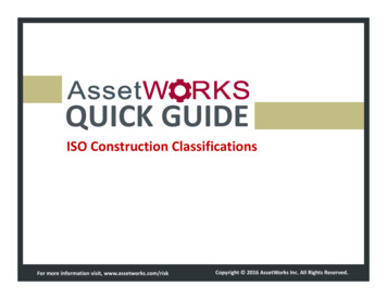
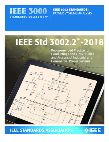
Explosion elements
N.E.C. Article 500 Code Sections Article 500 Hazardous LocationsArticle 501 Class I LocationsArticle 502 Class II LocationsArticle 503 Class III LocationsArticle 504 Intrinsically Safe SystemsArticle 505 Class 1, Zone 0, 1, and 2 LocationsArticle 510 Hazardous Location -SpecificArticle 511 Commercial GaragesArticle 513 Aircraft HangarsArticle 514 Gasoline Service StationsArticle 515 Bulk Storage PlantsArticle 516 Paint Spray Application
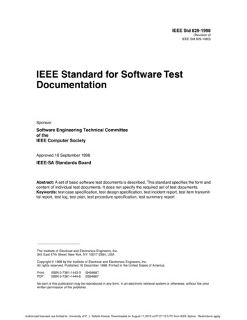
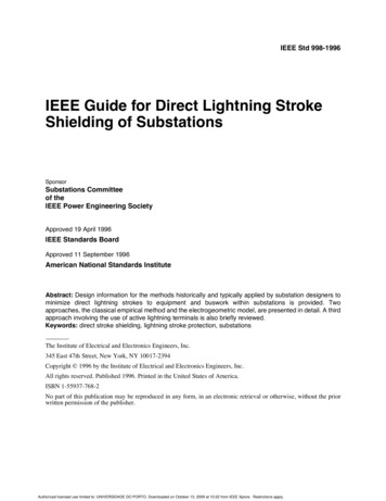
Class Locations N.E.C. Article 500.5 (B) An area whereFLAMMABLE GASES orVAPORS are or may bepresent in the air insufficient quantities toproduce explosive orignitable mixtures.
Class I Locations (Gases) N.E.C. Article 500.5 (B) An area whereFLAMMABLE GASES orVAPORS are or may bepresent in the air insufficient quantities toproduce explosive orignitable mixtures.
Class I Locations (Gases)CLASS I INDUSTRIES AND APPLICATIONS Natural or liquefied gas storage facilities Chemical plants Petroleum refineries Bulk handling or storage facilities for gasoline Dip tanks Storage tanks for flammable liquids or gas Spraying areas for paints or plastics Aircraft fuel servicing areas or hangers Well drilling (oil and gas), offshore or on Pipeline pumping areas Printing machine areas
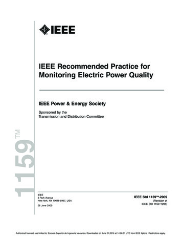
Class II Locations (Dust) N.E.C. Article 500.5 (C) An area where presence of COMBUSTIBLEDUST presents a fire or explosion hazard.
Class II Locations (Dust)CLASS II INDUSTRIES AND APPLICATIONS Grain storage, handling or processing plants Coal storage, handling or processing facilities Metal grinding or metal powder producing facilities Gunpowder or explosive (fireworks) plants Sugar, cocoa, spice or starch production orhandling facilities
Class III Locations (Fibers) NEC Article 500.5 (D) An area made hazardousbecause of the presence ofeasily ignitable FIBERS orFLYINGS, but in which suchfibers or flying's are not likely tobe in suspension in the air inquantities sufficient to produceignitable mixtures.
Class III Locations (Fibers) CLASS III INDUSTRIES AND APPLICATIONSCotton, textile or flax producing or handling facilitiesWood cutting, pulverizing or shaping plantsClothing manufacturing facilities
Locations Division 1Division 2
Division 1 Location NEC Articles 500.5(B)(1),500.5(C)(1) and 500.5(D)(1) An area where the HAZARDEXIST UNDERNORMALOPERATINGCONDITIONS. This alsoincludes locations where thehazard is caused by frequentmaintenance or repair work orfrequent equipment failure.
Division 1 Location(good engineering practice) Consider that there are 8,760 hours in a year. It isproposed that a Division I location would be onethat is within the flammable range more than 0.1%of the time, that is more than 8.76 hrs/yr. From a practical viewpoint on this basis, we wouldsuggest that any area in the flammable range 10hrs/yr. or more should be classified as Division 1.
Division 2 Location NEC Articles 500.5(B)(2) ,500.5(C)(2), and 500.5(D)(2)An area where ignitable gases,vapors, dust, or fibers arehandled, processed, or used, butwhich EXIST ONLY UNDERABNORMAL CONDITIONS, suchas containers or closed systemsfrom which they can only escapethrough accidental rupture orbreakdown. Note: No electrically conductivedust are included in Class II,Division 2 atmospheres.
Division 2 Location(good engineering practice) A Division 2 location would be one that is within the range more than 0.01%and up to 0.1 % of the time (0.876 hours to 8.76 hours). From a practical viewpoint on this basis, we would suggest that any area in theflammable range classified as Division 2, would be in the ra
NFPA 497 (we are currently at 2017 edition) NFPA 497M is a manual for the classification of gases, vapors, and dusts for electrical equipment in hazardous locations. It is a new document, extremely useful as a supplement to Underwriters' Laboratories (UL) for determining gas groups.