Transcription
CrashTest: A Fast High-Fidelity FPGA-BasedResiliency Analysis FrameworkAndrea Pellegrini, Kypros Constantinides, Dan Zhang, Shobana Sudhakar,Valeria Bertacco and Todd AustinUniversity of Michigan{apellegrini, kypros, danz, sshobana, valeria, austin}@umich.eduAbstract— Extreme scaling practices in silicon technology arequickly leading to integrated circuit components with limitedreliability, where phenomena such as early-transistor failures,gate-oxide wearout, and transient faults are becoming increasingly common. In order to overcome these issues and developrobust design techniques for large-market silicon ICs, it isnecessary to rely on accurate failure analysis frameworks whichenable design houses to faithfully evaluate both the impact ofa wide range of potential failures and the ability of candidatereliable mechanisms to overcome them. Unfortunately, whilefailure rates are already growing beyond economically viablelimits, no fault analysis framework is yet available that is bothaccurate and can operate on a complex integrated system.To address this void, we present CrashTest, a fast, highfidelity and flexible resiliency analysis system. Given a hardwaredescription model of the design under analysis, CrashTestis capable of orchestrating and performing a comprehensivedesign resiliency analysis by examining how the design reactsto faults while running software applications. Upon completion,CrashTest provides a high-fidelity analysis report obtainedby performing a fault injection campaign at the gate-levelnetlist of the design. The fault injection and analysis processis significantly accelerated by the use of an FPGA hardwareemulation platform. We conducted experimental evaluationson a range of systems, including a complex LEON-basedsystem-on-chip, and evaluated the impact of gate-level injectedfaults at the system level. We found that CrashTest is 1690x faster than an equivalent software-based framework, whenanalyzing designs through direct primary I/Os. As shown by ourLEON-based SoC experiments, when CrashTest can interfaceto the system under analysis through memory I/O, it exhibitsemulation speeds that are six orders of magnitude faster thansimulation.I. I NTRODUCTIONAs silicon process technology pushes towards smallertechnology sizes, device reliability is an emerging challengefor next-generation designs [5]. Silicon failure mechanismssuch as early transistor failures, gate-oxide wear-out, manufacturing defects, and radiation-induced soft errors threatenthe design’s reliability and severely reduce the yield andlifetime of future systems [20].These reliability challenges are usually addressed eitherby conservative high-margin design techniques that avoid themanifestation of device failures during the product lifetimeor by fault-tolerant techniques that detect failures and repairthe system functionality in the field during operation [19].Extreme technology scaling and process variation are makingthe use of classic conservative high-margin techniques inadequate to guarantee high system reliability [4]. The result is asteady shift towards the adoption of fault-tolerant techniquesinto the design flow of modern computing systems.Recently, a number of commercial microprocessors thatemploy fault-tolerant design techniques have appeared in themarketplace [10, 15]. Furthermore, the research area of faulttolerant design is a well studied area and several fault-toleranttechniques have been proposed in the literature [2, 6, 19].The need for Resiliency Analysis tools: Early in thedesign flow, system engineers need to assess the threats andthe reliability requirements of their design by employingresiliency analysis tools that first gauge the robustness ofthe bare unprotected design to check if it meets the specifiedreliability target. If the design does not meet the reliabilitytarget, a spectrum of fault-tolerant techniques must be considered and evaluated to select the one which meets the targetwith the best trade-off in implementation cost.The process of accurately assessing the robustness ofa bare unprotected design, or evaluating the effectivenessof candidate fault-tolerant techniques places the followingrequirements on the resiliency analysis infrastructure:Low-level Fault Analysis: High fidelity is a very importantaspect of the resiliency analysis framework. Using highlevel models of micro-architectural components with limitedknowledge of the underlying circuit is inadequate to performhigh-fidelity resiliency analysis. In order to correctly modelthe introduction, propagation, and possible masking of thefaults, the resiliency analysis framework must accuratelygauge circuit-level phenomena using a detailed low-levelmodel of the design under analysis (e.g., gate-level netlist).Flexible Fault Modeling: Due to the existence of multiplesilicon reliability threats, the resiliency analysis frameworkneeds to support an extensive collection of low-level faultmodels to cover silicon failure mechanisms that range fromtransient faults, to manufacturing faults, process variationinduced faults, and silicon wear-out related faults. Moreover,silicon fault modeling is an open area of research withcontinuous advancements [7, 11]. Often, new fault modelsare devised targeting emerging silicon failure modes or moreaccurately modeling existing failure mechanisms. Therefore,it is crucial that an analysis framework’s existing fault modelcollection can be easily upgraded with new fault models.Fast Design Simulation: The simulation of the design mustdeliver sufficient performance to enable the analysis of complex systems, including booting an operating system and runapplications. This will allow the assessment of the impact offaults at the full system while running nontrivial applications,and still providing a short evaluation turnaround.Flexible Simulation Interface: It is critical for the usabilityof the framework to provide an intuitive way to analyze awide range of designs and fault-tolerant techniques. Thus,a resiliency analysis framework demands a flexible interface and proper stubs to accommodate the evaluation ofdifferent systems. Given this challenging set of requirements
for resiliency analysis, we focused our efforts toward theuse of fault injection campaigns performed on gate-levelmodels and accelerated by FPGA-based hardware emulationto achieve both accuracy and performance.A. Contributions of this WorkIn this work we present CrashTest, a novel resiliencyanalysis framework that addresses the challenges discussedabove. We achieve this through the following contributions: We propose a new method to automatically orchestratea fault injection campaign and perform a detailed faultmonitoring and analysis on the gate-level netlist of thedesign. Our analysis approach accurately assesses theimpact of run-time injected faults on the operation ofa large complex system. The faults are injected intothe design using novel gate-level logic transformationsthat instrument the design’s netlist with fault emulationlogic. Our framework is augmented with a rich collection offault models that encompass all variants of faults designers would expect to encounter at run time, ranging fromsoft faults to permanent silicon defects. The differentfault models are defined by logic netlist transformationsthat can be easily modified and adapted by the user tomodel new failure mechanisms. We employed FPGA-based hardware emulation that enables the analysis of complex full-system designs whichcan boot an operating system and run applications.To the best of our knowledge, this is the first workthat performs gate-level fault injection on a full-systemdesign, and observes the impact of the injected faults atthe system level. We demonstrate the flexibility of our resiliency analysisframework by analyzing and presenting results for threecomplex designs including the LEON3 system-on-chip.The remaining of the paper is organized as follows:Section II briefly describes related previous work. Section IIIgives a high-level overview of our framework. Sections IVand V explain in detail our gate-level fault injection methodology and the FPGA-based fault emulation techniques usedby our framework, which we call CrashTest. Section VI evaluates the performance of CrashTest and presents experimental results that demonstrate its application and effectiveness.Finally, Section VII provides conclusions and directions forfuture work.II. R ELATED W ORKFault Simulation vs. Resiliency Analysis: Fault simulators are software tools that can determine the set of faultswhich can be exposed by a given test vector, and they aremainly used for ATPG (Automatic Test Pattern Generation)with the objective of measuring the fault coverage of a givenset of test vectors [7]. On the other hand, resiliency analysistools employ fault injection campaigns on a design executingtypical workloads to measure the impact that the injectedfaults have on the design’s operation and on the runningapplications.Even though both methodologies use fault models to simulate the effects of faults on the circuit under test, their goalsand requirements are fundamentally different. To prove theeffectiveness of a given set of test vectors, fault simulatorsneed to exercise faults in every node of the design for alimited amount of time. In contrast, resiliency analysis toolsneed to simulate the design under analysis for a significantamount of clock cycles in order to observe possible faulteffects at the application level. Moreover, resiliency analysistools usually employ Monte Carlo simulation methodologiesand inject only the number of faults required to provideadequate statistical confidence in the results obtained. Due tothese major different characteristics of the two methodologies, ATPG fault simulators cannot be efficiently used as afault injection substrate to perform design resiliency analysis.Several works in literature have proposed resiliency analysis frameworks that are based on fault injection campaigns.These works can be partitioned into software-based andhardware-based resiliency analysis, based on the methodology used to perform the fault simulation and analysis [16].Software-Based Resiliency Analysis: Often, softwarebased fault injection is preferred to hardware-based solutions due to its low cost, less complex development cycle,flexibility of customization, or simply because no low-levelhardware model of the design is available. There are severalsoftware-based resiliency analysis frameworks presented inliterature [12, 17, 21]. Although they have many advantages,the speed of low level (e.g., gate-level) simulations does notmake these solutions feasible for analyzing complex designsor complete systems running software applications.Hardware-Based Resiliency Analysis: The performancelimitation of the software-based fault injection approach canbe addressed by employing hardware-based fault injection.Hardware-based resiliency analysis frameworks usually employ FPGAs (Field Programmable Gate Arrays) that arecapable of emulating the fault injected design orders ofmagnitude faster than software-based approaches, thereforesignificantly speeding up the fault simulation and analysisprocess. Although the use of FPGA emulation platforms addresses the limited performance of the software frameworks,it introduces some major challenges in automating the faultinjection and the analysis process. Furthermore, it is difficultto map on the FPGA fabric complex fault models. Hence,the previously proposed hardware-based resiliency analysisframeworks were limited to simple transient fault models andstuck-at faults [9, 14].III. F RAMEWORK OVERVIEWThe goal of our resiliency analysis framework is to provide a fast, high-fidelity, and comprehensive analysis of theeffects of several different fault classes on the applicationsrunning on a design under analysis (this could be either anunprotected design or a fault-tolerant design).Given the specification of the design under analysis ina hardware description language (HDL), CrashTest automatically orchestrates a fault injection/analysis campaign.This process is composed of two stages: (i) the front-end
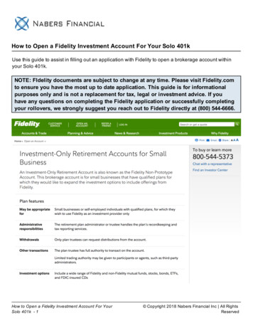
Fault-InjectionReady NetlistFaultLibraryFault Injection& SimulationFrameworkBack-EndMonte CarloSimulationTechnologyIndependentGate-Level NetlistFault SimulationParametersFPGA-BasedSynthesisFault InjectionParametersGate-Level ionStimuliFig. 1. Overview of the resiliency analysis framework: The framework is composed of (i) the front-end stage generating the fault injection-ready gate-levelnetlist and (ii) the back-end stage performing fault injection and analysis and generating the final resiliency analysis report.translation that generates the fault-injection ready gate-levelnetlist of the design under analysis, and (ii) the back-endfault simulation and analysis that performs the actual faultinjection and fault monitoring and evaluates the effects of theinjected faults. Figure 1 represents an overview Crashtest.A FPGA solution is the only one that can provide enoughperformance to run software applications on large and complex designs. However, a major cost in the adoption of thissolution is the overhead necessary to map the design on theFPGA fabric. For big designs the time needed to obtain thenetlist mappable on the FPGA device can be prohibitivelylong. To reduce this overhead, in Crashtest multiple faultsare inserted in the netlist mapped on the FPGA. These faultscan be singularly activated dynamically through software,thus sharing the mapping cost on several analysis.Framework Front-End: First, the HDL model of thedesign under analysis is provided by the user (either inVerilog or VHDL). Subsequently, the HDL model of thedesign is synthesized by the front-end stage of the frameworkusing a standard cell library to get a gate-level netlist of thedesign. CrashTest does not require the design to be mappedwith any particular library as long as it is properly modifiedto support the fault models.For each standard cell in the library (i.e., a combinationalgate or a sequential element), CrashTest is enhanced with agate-level logic transformation that modifies the netlist andinserts extra fault injection logic. This extra logic can beactivated at runtime to emulate the effects of a fault injectedinto the cell. We developed a wide range of fault modelsand gate-level logic transformations to provide the capabilityof emulating different failure mechanisms. The collection ofall logic transformations is stored in the framework’s faultlibrary. Based on the injection parameters selected by theuser (i.e., the fault models and the injection locations), theframework automatically generates the fault injection-readynetlist of the design using the logic transformations in thelibrary. This netlist is then delivered to the fault analysissimulator at the back-end stage.Framework Back-End: At the framework back end, thefault injection-ready netlist is re-synthesized and mappedon an FPGA. At this point the fault injection and analysiscampaign is ready to begin. Based on the fault simulationparameters given by the user, the fault injection/analysisemulator injects faults at different sites in the netlist andmonitors their propagation and impact on the design andthe running applications. During fault emulation, the designunder analysis is exercised with the application stimuli.To gain statistical confidence on the provided results, theexperiments are repeated in a Monte Carlo simulation modelby altering the fault sites and/or the application stimuli. Afterrunning a sufficient number of experiments to gain statisticalconfidence, the results are aggregated into the resiliencyanalysis report which is the final deliverable of the CrashTestframework. In the following sections, we describe each stepof the CrashTest framework in more detail.IV. G ATE -L EVEL FAULT I NJECTION M ETHODOLOGYTechnology Independent Logic Synthesis - The firststep in the front-end stage of the CrashTest frameworkis to convert the user-provided high-level HDL model ofthe design under analysis into a common format that theframework can analyze and get an accurate list of candidatecircuit locations to perform gate-level fault injection. Thisis achieved by performing logic synthesis with SynopsysDesign Compiler targeting a technology-independent standard cell library (GTECH). The resulting gate-level netlist iscomposed of simple logic gates (e.g., AND, OR, NOT, FlipFlops, etc,) and it is free from any fabrication technologyrelated characteristics and properties. This gate-level netlistis subsequently parsed to generate a list of all possible faultinjection locations in the circuit (i.e., a list of all logicgates and flip-flops in the design). This list is used by theuser to specify the fault injection locations; alternatively, ifrandomized fault injection is desired, random selection offault sites can be performed by the framework.Netlist Fault Injection Instrumentation - Once faultlocations are selected, the gate-level netlist is instrumentedwith extra fault injection logic that, when enabled, emulates the effects of the injected faults. Each fault modelsupported by the framework is associated with a gate-levellogic transformation that modifies the netlist and instrumentsit with the extra fault injection logic. The collection ofgate-level logic transformations composes the framework’sfault library. This modular design makes it fairly easy toupgrade the framework with new fault models by simplyimplementing and adding new netlist logic transformationsinto the fault library. Our resiliency analysis framework isalready enhanced with a collection of fault models and theircorresponding netlist logic transformations. This fault model
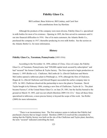
Transistor-levelNAND2 gateVddABCBn1AGndFault Symptom TableInstrumentation logic for -CXX1XBridge-C-n111X0AB0CRandom ValueABAB1FaultInject(a)(b)(c)Fig. 2. Logic Transformations - Bridge Fault: The CMOS transistor-level design of a gate in (a) is used to generate the gate’s fault symptom table forthe fault model shown in (b). Part (c) shows the instrumentation logic for emulating the effects of the Bridge-A-B fault.Fault-Injection Ready NetlistStuck-at: The stuck-at fault model is the industry standard model forcircuit testing. It assumes that a circuit defect behaves as a node stuckat logical 0 or 1. The stuck-at fault model is most commonly used tomimic permanent manufacturing or wearout-related silicon defects.Stuck-open: The stuck-open fault model assumes that a singlephysical line in the circuit is broken. The unconnected node is not tiedto either Vcc or Gnd and its behavior is rather unpredictable (logical 0or 1 or high impedance). The stuck-open fault model is commonlyused to mimic permanent defects that are not covered by the stuck-atfault model.Bridge: The bridge fault model assumes that two nodes of a circuit areshorted together. The behavior of the two shorted nodes depends onthe values and the strength of their driving nodes. The bridge faultmodel covers a large percentage of permanent manufacturing orwearout-related defects.Path-delay: The path-delay fault model assumes that the logicfunction of the circuit is correct, however, the total delay in a pathfrom its inputs to outputs exceeds the predefined threshold and itcauses incorrect behavior. The path-delay fault model is mostcommonly used to mimic the effects of process variation or devicedegradation due to age-related wearout.Single Event Upset: The single event upset (SEU) fault modelassumes that the value of a node in the circuit if flipped for one cycle.After this one cycle upset, the node behaves as expected. The SEUfault model is used to mimic transient faults that are most commonlyused by cosmic radiation or alpha particles.TABLE IFault models: CrashTest is enhanced with an extensive collection of faultmodels. These fault models cover transient faults as single event upsets andalso a variety of permanent hard faults related to manufacturing, wearout,and process variation silicon defects.collection covers an extensive spectrum of silicon failuremechanisms ranging from transient faults due to cosmic raysto permanent faults due to silicon wearout. Table I shows alist of supported fault models with a brief description.Gate-Level Logic Transformations - Some fault modelsrequire trivial gate-level logic transformations. For example,the instrumentation needed to emulate a stuck-at fault is just amultiplexer that controls the output of the faulty gate and hasone of its inputs connected to logic zero/one. However, thereare fault models that are more complex and affect the designat the transistor level. For example, the bridge fault modelassumes that two nodes in the design are shorted together.To emulate the effect of a bridge fault model with highfidelity, we simulated the faulty gates at the CMOS transistorlevel and generated the corresponding fault symptom tables.To illustrate this process, Figure 2(a) shows the CMOStransistor level representation of a NAND2 logic gate, whileFigure 2(b) shows the respective fault symptom table of theFault InjectionSite 1FIScanInDQClk Fault InjectionSite 2Fault InjectionSite NFIDQClkFIDQScanOutClkFault Injection Scan ChainFig. 3. Fault injection scan chain: The netlist is instrumented with faultinjection logic for multiple faults. The scan chain controls the fault injectionduring emulation.bridge fault model.By observing the fault symptom table we noticed that forsome inputs the effects of the fault are masked, thus the faultygate behaves exactly like a fault-free gate. However, for otherinput combinations the fault’s effects propagate to the gate’soutput and result in an unstable output signal that could beeither a logic zero or one (Random Value in Figure 2(c)). Theframework’s fault library is populated with a fault symptomtable for each combination of a standard cell library gate anda supported fault model. Given the gate type and the faultmodel, the netlist instrumentation routine accesses the faultlibrary and applies the respective logic transformation thatwould insert the necessary instrumentation logic to emulatethe fault effects. Figure 2(c) shows the instrumentation logicneeded to emulate the effects of a bridge fault between thecircuit nodes A and B of the NAND2 gate. A fault-tolerantdesign should be able to handle these faults and either maskthe errors introduced or reconfigure itself to not use the faultypart of the design.Fault Injection Scan Chain - To avoid re-instrumentingthe netlist each time a new fault is injected and simulated,the netlist can be instrumented for multiple faults at multiplelocations. This accelerates the fault emulation at the backend of the framework, but it also increases the instrumentedcircuit size. The insertion of each fault into the netlist alsoadds an extra control signal used for enabling and disablingthe inserted fault at runtime (for instance, signal Fault Injectand Random Value in 2(c)). During emulation, these signalsare accessible by the Fault Injection Manager (see Figure 5).The Path-Delay Fault Model - The gate-level logictransformations employed for the rest of the supported faultmodels are similar to the one presented in Figure 2(c) forthe bridge fault. One exception is the path-delay fault model
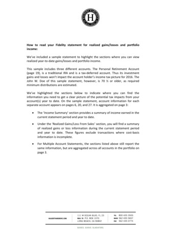
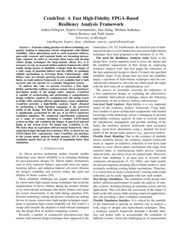
Affected Flip-FlopsDQ1CombinationalLogicDFI FaultyGateClkQClk0DQ1ClkFIFig. 4. Logic transformation for the path-delay fault model: If the output ofthe faulty gate changes in a given cycle, all affected flip-flops miss latchingthe newly computed value and hold the previous cycle’s value.which has slightly different characteristics. Path-delay faultsare characterized by slower combinational logic gates thatcause longer path delays than the ones expected at designtime. Whenever these slower gates get exercised, they canincrease the path delay beyond the critical path delay andcause timing violations (i.e., the flip-flops at the end ofthe path miss to latch the newly computed value). In ourframework, the effects of the path-delay fault model areemulated by the gate-level logic transformation shown inFigure 4. To determinate the set of flip-flops that are affectedby the slower faulty gate, we trace forward through thecombinational logic and find all those flip-flops that havea path that includes the faulty gate. From that set of flipflops we choose only those that have a path delay with atiming slack smaller than a predefined threshold specifiedby the user (i.e., the expected delay due to the faulty gate).V. FPGA-BASED FAULT E MULATIONCrashTest employs an FPGA platform to emulate thefault injected hardware and accelerate the fault simulationand analysis process. The first step in this process it tosynthesize and map the fault injection-ready netlist to thetarget FPGA. To provide a standard simulation interfacethat is independent of the design under analysis, we addan automatically generated interface wrapper to the faultinjected-ready netlist. This interface wrapper provides aseamless connection with the fault injection manager, whichis an automatically generated software program responsiblefor orchestrating the fault injection and analysis campaign.The interface wrapper and the fault injection manager areconnected through an on-chip interconnect bus. Figure 5shows the major components and the data-flow of the faultinjection, simulation and analysis process.Fault Injection Manager - During the emulation andanalysis process, the FPGA-mapped design is exercised andcontrolled by the fault injection manager. In our experimentswe used a Xilinx Virtex-II Pro FPGA, which has two onchip PowerPC processors, with the fault injection managersoftware running on one of them. Alternatively, the faultinjection manager can also run on a soft-core (e.g., Microblaze). Specifically, the fault injection manager is responsiblefor the following tasks:InstrumentedFault-InjectionReady NetlistInputRegisters0FIFOInterface Wrapper Interrupt CounterOutput RegistersGate-Level Logic Transformationfor the Path-Delay Fault ModelOn-chip Processor CoreFault Injection ManagerOff-chip Memory- Stimulus- Fault injection parameters- Golden results- Results/StatisticsFig. 5. FPGA-Based fault injection and simulation: The FPGA-mappednetlist is wrapped by a standard interface providing a seamless connectionto the fault injection manager that is running on an on-chip processor core.- Feed the instrumented injection scan chain with all thecontrol signals required to perform the fault injection campaign. This is done through a FIFO queue updated whenevera new fault is injected into the design. The fault injectionparameters (i.e., fault location and time) are stored on anoff-chip memory accessible by the fault injection manager.- Stimulate the design through the input registers. Theapplications stimulus is either provided by the user or automatically generated, and it is stored in the off-chip memory.- Monitor the output of the FPGA-mapped design for errorsthrough the output registers. The output is compared to agolden output that is collected through a fault-free versionof the same design and it is stored in the off-chip memory.- Maintain fault analysis statistics and store the results to theoff-chip memory for later processing.- Synchronize the FPGA-mapped design with the fault injection process through the interrupt counter.VI. F RAMEWORK E VALUATIONIn this section, we evaluate our FPGA-based resiliencyanalysis infrastructure and compare its performance to anequivalent software-based implementation. We also performan initial examination, using the CrashTest infrastructure, ofthe effects of different fault models in design resiliency.A. Experimental MethodologyBenchmark Designs - For the evaluation of CrashTestwe used three benchmark designs. These benchmark designs and their characteristics are shown at Table II. Thechip-multiprocessor (CMP) interconnect router implementsa wormhole router pipelined at the flit level with creditbased flow control functionality for a two-dimensional torusnetwork topology [13]. We used SPEC CPU2000 communication traces derived from the TRIPS architecture [18] toprovide application stimuli to the router. The DLX coreis a 32-bit 5-stage in-order single-issue pipeline runningthe MIPS-Lite ISA. Finally, the LEON3 is a system-onchip including a 32-bit 7-stage pipelined processor runningthe SPARC V8 architecture, an on-chip interconnect, basicperipherals and a memory controller [10]. The LEON3 SoCis able of booting an unmodified version of Linux 2.6. TheLEON processor was configured without on-chip caches andfaults were injected only in the core component.Netlist Fault-Injection Instrumentation - The HDLmodel of the design under analysis is synthesized usingthe Synopsys Design Compiler and the GTECH standardcell library. The resulting netlist is a technology-independent
Benchmark Logic GatesName(GTECH)FlipFlopsCMP Router16,5441,705DLX ptionchip-multiprocessor interconnect router for a2D mesh network with 32-bit flits5-stage in-order DLX pipeline runningMIPS-Lite ISASystem-on-chip with a 7-stage pipeline 32-bitprocessor compliant with the SPARC V8architecture, an on-chip interconnect, basicperipherals and a memory controller.TABLE IIBenchmark Designs: Characteristics of the benchmark designs used toevaluate the CrashTest framework.Confidence Level 95%Number of FaultInjections (Sample Size)2565121024204840968192Confidence IntervalCMP RouterDLX CoreLEON3(18249 gates) (17045 gates) (73237 2.141.351.331.490.80.781.02TABLE IIIStatistical Confidence: The Table shows the confidence level of the resultsobtained when different number of faults are injected during the injectioncampaigns for our benchmark designs.GTE
Report Framework Back-End Fig. 1. Overview of the resiliency analysis framework: The framework is composed of (i) the front-end stage generating the fault injection-ready gate-level netlist and (ii) the back-end stage performing fault injection and analysis and generating the final resiliency analysis report.