Transcription
, SDMS Documentv117700Contract No. 68-W-98-210RACIIQUALITY ASSURANCE PROJECT PLANADDENDUM NO, 1SCORPIO RECYCLING INC SUPERFUND SITEREMEDIAL INVESTIGATION/FEASIBILITY STUDYTOA BAJA, PUERTO RICOWork Assignment No.: 141-RICO-02HAPrepared for:TT OT -. 1 T lJLlARemedial Response, Enforcement Oversightand Non-time Critical Removal Activitiesat Sites of Release or Threatened Releaseof Hazardous Substances in EPA Region II 9300547
QUALITY ASSURANCE PROJECT PLANADDENDUM NO. 1SCORPIO RECYCLING INC SUPERFUND SITEREMEDIAL INVESTIGATION/FEASIBILITY STUDYTOA BAJA, PUERTO RICOWork Assignment No.: 14i-RICO-02HAPrepared for:U.S. Environmental Protection Agency290 BroadwayNew York, New York 10007-1866Prepared by:CDM Federal Programs Corporation1607 Ponce de Leon AvenueCobian's Plaza, Suite 405San Juan, Puerto Rico 00909EPA Work Assignment No.EPA RegionContract No.CDM Federal Programs CorporationDocument No.Prepared bySite ManagerTelephone NumberEPA Remedial Project ManagerTelephone NumberDate -04910CDMNancy Rodriguez(787) 620-5808Ramon Torres(787)977-9744September 7, 2004300548Scorpio QAPP Addendum No. 1
Cobian's Plaza, 1607 Ponce De Leon AvenueSan Juan, Puerto Rico 00909tel: 787 620-5808fax: 787 620-5803September 7, 2004Mr. Ramon TorresRemedial Project ManagerU.S. Envirorunental Protection AgencyCaribbean Environmental Protection DivisionCentro Europa Building, Suite 4171492 Ponce de Leon AvenueSanturce, Puerto Rico 00907PROJECT:RAG II Contract No.: 68-98-210Work Assigriment No.: 141-RICO-02HADOC. CONTROL NO.:3223-141-PP-QAPP-04910SUBJECT:Quality Assurance Project Plan Addendum No. 1Scorpio Recycling Superfxmd SiteRemedial Investigation and Feasibility StudyToa Baja, Puerto RicoDear Mr. Torres:CDM Federal Programs Corporation (CDM) is pleased to submit this Addendum No. 1 tothe Final Quality Assurance Project Plan for the Remedial Investigation and FeasibilityStudy at the Scorpio Recycling Superfund site in Toa Baja, Puerto Rico.This QAPP Addendum includes:(1)Two new field procedures:a) Downhole Video Surveyb) Monitoring Well Abandonment(2)A revised procedure for monitoring well installation due to changes in theoriginal design(3)Changes in CDM personnel(4)A proposed schedule for monitoring well installation, monitoring wellabandonment and groundwater sampling activities(5)Copies of the revised Technical Standard Operation Procedures300549consulting engineering construction operations
If you have any questions regrading this addendum, please contact Nancy Rodriguez at(787) 620-5808 or myself at (212) 785-9123.Very truly yours,CDM FEDERAL PROGRAMS CORPORATIONJeanne Litwin, REMRACII Technical Operations ManagerEnclosurecc:F. Rosado, EPA Region IID. Butler, EPA Region IIEPA QA Coordinator, EPA Region IIR, Goltz/PSO File, CDMN. Rodriguez, CDMJ. Oxford, CDMField TeamRAC II Document Control300550f
ua ui "w'tiw«M-TU.S. EPA CONTRACT NO. 68-W-98-210QUALITY ASSURANCE PROJECT PLAN ADDENDUM NO, 1SCORPIO RECYCLING INC SUPERFUND SITEREMEDIAL INVESTIGATION/FEASIBILITY STUDYTOA BAJA, PUERTO RICOWORK ASSIGNMENT NO.: 141-RICO-02HADOCUMENT NO.: 3223-141-PP-QAPP-04910vcd JOP/DateNancy RodriguezRAC II Site Managery f A / L j U , iJiKA il Jeaime Litwin, REMRAC II Technical Operations Manageryi{ , Gerfrge L1/RAC 11 QA Director: Tg /t/Kg Li-funDateDateRamon TorresEPA Work Assignment MangerDateQA OfficerEPA Region IIDateScorpio QAPF Addendum No. 1300551
9I300552
Contents(Sections that are new or that require modifications to the Final Quality Assurance Project Plan(July 12, 2002) are bolded in the Table of Contents)1.0 INTRODUCTION1-11.1Project Description1-21.2Site Location1-21.3Site Description1-21.4Geology and Hydrogeology1-31.4.1 Regional Geology and Hydrogeology1-31.4.2 Project-Specific Geology and Hydrogeology1-71.5Site History1-91.6Objectives and Scope1-102.0 PROJECT ORGANIZATION AND ntractors2.4Documentation and Records2.5Special Training Requirements or Certification2.6Reports to Management3.0 SCHEDULE AND SITE MANAGEMENT PLAN3.1Schedule3.2Access3.3Waste Disposal4.0 SAMPLING PROGRAM RATIONALE4.1Topographic Survey4.2Ecological Resource Survey and Characterization4.2.1 Characterization of Wildlife Habitat/Usage4.3Monitoring Well Installation4.4Downhole Gamma Logging4.5Slug Tests4.6Synoptic Water Level Elevation Measurements4.7Continuous Water Level Monitoring4.8Soil Boring Sampling;4.9Groundwater Sampling4.10 Analytical Procedures4.11 Sample Identification and Tracking4.11.1 Sample Identification4.11.2 Sample Type4.11.3 Sample Numbers4.11.4 Sample Depth Identifiers4.11.5 QC Sample Numbering System2-12-12-22-32-42-52-53-1. . . . 3-1.3-13-14-14-14-24-24-14-4 '4-54-5 ,4-54-64-64-74-74-74-74-84-84-9CDMScorpio Draft QAPP Addendum.wpd300553
4.124.134.144.11.6 Sample LabelsOn-going QuaUty ControlDownhole Video SurveyMonitoring Well Abandonment,.4-94-94-14-25.0 FIELD PROCEDURES5-15.1Mobilization5-15.2Decontamination Procedures5-25.2.1 Personal Protective Equipment5-35.2.2 Field Monitoring and Geophysical Logging Equipment5-35.2.3 Well Casings5-35.2.4 DrilUng Equipment and Other Large Pieces of Equipment5-35.2.5 Sampling Apparatus. . . . ; . . . . . 5-35.2.6 Decontamination Equipment5-45.3Field Notations5-55.4Topographic Survey5-55.5Ecological Resources Survey5-55.5.1 Wildlife Habitat/Usage Characterization5-65.5.1.1Preparatory Activities5-65.5.1.2Field Equipment5-65.5.1.3Procedures5-65.6Monitoring Well Installation5-15.6.1 Preparatory Activities5-85.6.2 Field Equipment5-85.6.3 Procedures for Monitoring Well Installation5-15.6.3.1Borehole Installation5-15.6.3.2Bedrock Coring5-95.6.3.3 Monitoring Well Installation5-25.7Downhole Gamma Logging: 5-115.7.1 Preparatory Activities5-125.7.2 Field Equipment5-125.7.3 Procedures5-125.8Slug Tests5-125.8.1 Preparatory Activities5-135.8.2 Field Equipment5-135.8.3 Procedures5-135.9Synoptic Water Level Measurements5-135.9.1 Preparatory Activities5-135.9.2 Field Equipment5-145.9.3 Procedures5-145.10Continuous Water Levels Monitoring5-145.10.1 Preparatory Activities5-145.10.2 Field Equipment5-145.10.3 Field Procedures5-155.11Monitoring Well Soil Boring Sampling5-16CDMScorpio Draft QAPP Addendum.wpd300554
y Activities.;5-16Field Equipment5-16Procedures5-17Sample Container FilUng Procedure for Subsurface Soil5-195.11.4.1Procedures for Collecting Samples forTOC Analyses5-19Groundwater Sampling5-205.12.1 Preparatory Activities5-215.12.2 Field Equipment5-215.12.3 Procedures5-215.12.4 Sample Collection5-225.12.4.1Sample Container Filling Procedures for VOCGroundwater Samples5-225.12.4.2Sample Container Filling Procedures for TCLExtiactable Organic Compovmds5-225.12.4.3Sample Container Filling Procedures for TALInorganics5-235.12.4.4Sample Container FilUng Procedures forConventional Parameters5-235.12.5 On-Site Field Screening5-235.12.5.1Sample Container Filling Procedures for Ferrous IronGroundwater Samples5-23Demobilization5-24Downhole Video Sxuvey5-45.14.1 Preparatory Activities5-45.14.2 Field Equipment5-45.14.3 Field Procedures5-55.14.3.1 Downhole Video Survey5-5Monitoring Well Abandonment5-65.15.1 Field Procedures5-66.0 QUALITY ASSURANCE PROJECT PLAN6-16.1Data Quality Requirements and Assessment6-16.1.1 Accuracy, Precision and Sensitivity of Analysis6-16.1.2 Field Representativeness, Completeness and Comparability6-26.1.3 Field Quality Contiol Samples6-46.2Laboratory Scheduling6-66.3Documentation6-76.3.1 Field Logbook6-76.3.2 Organic or Inorganic RAS Combination Forms/DESA Paperwork . . . 6-86.3.3 CDM Federal Laboratory SubcontractorChain-of-Custody Forms6-86.3.4 Sample Label6-86.3.5 Sample Custody and Shipment Documentation6-96.3.6 Sample Trip Reports6-10CDMScorpio Draft QAPP Addendum.wpd300555
le BottlesSample Handling, Packaging and Shipping6.5.1 Packaging6.5.2 Marking/Labeling6.5.3 Shipping Papers6.5.4 Transportation6.5.5 Notification of Sample ShipmentInstiument/Equipment Testing, Inspection, and Maintenance RequirementsInstrument Calibration and FrequencyInspection/Acceptance Requirements for SuppUes and ConsumablesData Acquisition Requirements (Non-Direct Measurement)Data ManagementData Reduction'.Data ValidationData ReportingInternal QC Checks and Frequency for Laboratory Analysis6.14.1 Action Required If QC Limits Are Exceeded6.14.2 Non-Standard AnalysisPARCCS Definition and EvaluationSystem and Performance Audits;6.16.1 Corrective 6-166-186-196-206-236-246-266-276-296-307.0 REFERENCES7-18.0 A C R O N Y M S8-1ivCDMScorpio Draft QAPP Addendum.wpd300556
APPENDICESAppendix AProject-Specific Groundwater Sampling Procedure Low-Stiess (Low-Flow)Purging and SamplingAppendix BCDM Technical Standard Operating Procediues (revised version included)1-2Sample Custody1-6Water Level Measurement2-1Packaging and Shipping of Environmental Samples3-4Geophysical Logging, Calibration, and Quality Control3-5Lithologic Logging4-1Field Logbook Content and Control4-2Photographic Documentation of Field Activities4-3Well Development and Purging4-4Design and Installation of Monitoring Wells in Aquifers4-6Hydraulic Conductivity TestingAppendix CProject-Specific Standard Operating ProceduresAppendix DCRQLs, MCLs AND ARARsAppendix ELloyd Kahn MethodLIST4-14-24-3O F TABLESAnalytical Sampling Program SummaryAnalytical Detection LimitsQuality Assurance/Quality Contiol Data Quality Objectives for Precision, Sensitivity, and Completeness of AnalysesSample Documentation DistiibutionField Measurement EquipmentEquipment CalibrationSupplies and Consumables Tracking LogLaboratory QC SamplesOF FIGURESSite Location MapSite MapGeneral Bedrock Geology of the Bayamon AreaStiatigraphic Column of the Bayamon AreaSchematic Geologic Cross Section Across the Vega Alta-Bayamon AreaNorth-South Hydrogeologic Cross Section Across the Bayamon AreaOutcrop and Altitude of the Cibao FormationCDMScorpio Draft QAPP Addendum.wpd300557
1-81-91-10Thickness of Surficial Deposits in the Bayamon AreaWater Table Contour Map for the Upper Aquifer, Bayamon AreaWater-Bearing Characteristics of Aquifers in the Bayamon Area2-1Project Organization2-2Field Change Request3-1Project Schedule4-14-24-35-15-2Proposed Monitoring Well Sampling LocationsProposed Supply Well Sampling LocationsRevised Monitoring Well Sampling LocationsMonitoring Well Construction DiagramRevised Monitoring Well Construction Diagram6-16-26-36-46-56-66-76-86-96-106-11Organic Traffic Report and Chain-of-Custody RecordInorganic Traffic Report and Chain-of-Custody RecordEPA Region 2 Laboratory Chain of Custody/Field Data FormRAS Adhesive LabelsCustody SealEquipment Calibration LogMaintenance and Calibration RecordNonconforniance ReportItem Inspection ReportRegion Copy FORMS II Lite Traffic Report & Chain of Custody RecordLaboratory Copy FORMS II Lite Traffic Report & Chain of Custody RecordCDMviScorpio Draft QAPP Addendum, wpd300558
D I S T R I B U T I O N LISTRamon Torres, EPA (2)Fernando Rosado, EPADeborah Butier, EPA (Letter Only)EPA QA Coordinator, EPA Region IINancy Rodriguez, CDMJeanne Litwin, CDMRobert D.Goltz, CDMJeniffer Oxford, CDMField Team (2 copies)Document ControlCDMviiScorpio Draft QAPP Addendum.wpd300559
CROSSWALK BETWEEN EPA QA/R-5 AND SCORPIO RECYCLING SITE QAPP FORMATQA/R-5 ELEMENTSSCORPIO RECYCLING SITEQAPP SECTIONAlTitie and Approval SheetA2Table of ContentsA3Distiibution ListA4Project/Task OrganizationA5A6Problem Definition/BackgroundProject/Task DescriptionSection 1.0 - Includes Project Description,Site Location, Site Description, Geology andHydrogeology, Site History, and Objectivesand ScopeSection 3.1 - ScheduleA7Quality Objectives and Criteria forMeasurement DataSection 6.1 - Data QualityRequirements and AssessmentSection 6.14 - Internal Quality ControlChecks and Frequency for LaboratoryAnalysisA8Special Training Requirements orCertificationSection 2.5 - Special TrainingRequirements or CertificationA9Documentation and RecordsSection 2.4 - Documentation and RecordsSection 2.6 - Reports to ManageBlData Collection DesignSection 4.0 - Sampling Program RationaleB2Sampling Methods RequirementsSection 5.0 - Field ProceduresB3Sample Handling and CustodyRequirementsSection 6.3 - DocumentationSection 6.4 - Sample BottlesSection 6.5 - Sample Handling, Packagingand ShippingB4Analytical Methods RequirementsSection 4.7 - Analytical Procedures Title and Approval SheetCDMTable of ContentsDistiibution ListSection 2.0 - Project Organization andResponsibilitySection 3.0 - Schedule and Site ManagementPlanVIIIScorpio Draft QAPP Addendum.wpd300560
Section 4.8 - Ongoing Quality ContiolSection 6.1.3 - Field QuaUty ContiolSamplesSection 6.1.4 - Internal Quality ContiolChecks and Frequency for LaboratoryAnalysisSection 6.1.5 - PARCCS Definition and" EvaluationB5Quality Contiol RequirementsB6Instiument/Equipment Testing,Procedures and Schedules Inspection,and Maintenance RequirementsSection 6.6 - Instrument/EquipmentTesting, Inspection, and MaintenanceRequirementsB7Instiument CaUbration and FrequencySection 6.7 - Instrument Calibration andFrequencyB8Inspection/ Acceptance Requirementsfor Supplies and ConsumablesSection 6.8 - Inspection/AcceptanceRequirements for Supplies andConsumablesB9Data Acquisition RequirementsSection 6.9 - Data Acquisition RequirementsBIOData Quality ManagementSection 6.10 - Data ManagementCIAssessments and Response ActionsSection 6.16. - System and PerformanceAuditsC2Reports to ManagementSection 2.0 - Project Organization andResponsibilityDlData Review, Validation, andVerification RequirementsSection 6.11 - Data ReductionD2Validation and Verification MethodsSection 6.12 - Data ValidationD3Reconciliation with Data Use to AssessPARCC for QuaUty ObjectivesMeasurementSection 6.15 - PARCCS Definition andEvaluationCDMIXScorpio Draft QAPP Addendum.wpd300561
CD:no foOne300562
Revision.SectionDate September 7. 2004PageIri.Section 1IntroductionUnder the United States Environmental Protection Agency (EPA) Response Action Contiact(RAC) II program. Work Assigrunent 141-RICO-02HA, CDM Federal Programs Corporation(CDM) is performing a Remedial Investigatiori/Feasibility Study (RI/FS) at the ScorpioRecycling Inc. SUperfxmd Site (the Site) located in Toa Baja, Puerto Rico. As agreed with EPA,additional field w ork is warranted at the Site. The additional field work includes instaUation of3 new monitoring wells and abandonment of the 3 obstructed wells. The TechnicalMemorandum dated March 12, 2003 discusses in more detail the monitoring well status at theScorpio Recycling Inc. Superfund Site. This document serves as an A d d e n d u m to the Site FinalQuality Assurance Project Plan (QAPP) and covers monitoring well installation, downholevideo survey and monitoring well abandorunent.This QAPP Addendum No. 1 outlines specific field investigation techniques to be utilizedduring the monitoring well installation, monitoring well abandonment and downhole videosurveying. This Addendum includes only sections that are new or that require modifications ofthe Final QAPP (July 12, 2002). These sections are bolded in the Table of Contents. AU sectionsof the Final QAPP that are appUcable to the monitoring well installation (e.g. samplepackaging, decontamination, and CDM's Response Action Contiact (RAC) Il-Specific TechnicalStandard Operating Procedure (TSOPs)) will govern the conduct of that work.CDMScorpio Draft QAPP Addendum.wpd300563
C/3nno13300564
Revision.SectionDate September 7, 2004Page2:1Section 2Project Organization and ResponsibilityChanges to the project personnel are shown in bold print in the listing below. AllresponsibiUties remain the same as outUned in the Final QAPP.Overall Project Coordination (SM)Procurement/Subcontract ManagementProcurement SpecialistCorporate Health and Safety OfficerSenior Geologist (SG)Project Hydrogeologist (PH)/Field Geologist (FG)RI Task LeaderField Team Leader (FTL)Field Scientist (FS)Field Scientist (FS)Health Risk AssessorEcologistAnalytical Services Coordinator (ASC)Health and Safety CoordinatorSite Health and Safety CoordinatorRAS Laboratory AnalysesRAS Laboratory QCRAS Data ValidationNon-RAS Laboratory AnalysesNon-RAS Laboratory QCNon-RAS Data VaUdationData Processing ActivitiesData Processing QCQuality Assurance ManagerRAC II QA Coordinator (RQAC)RQAC DesigneeTechnical System AuditsInternal System AuditsNancy RodriguezVernon WimberlySandra DietiichChuck MyersSusan Schofield, PGMichael Valentino, PGMichael Valentino, PGJose ReyesSeth KelloggApril CarusoKristen CarpenterMurray WadeScott Kirchner, Certified HazardousMaterials Manager (CHMM)Jeniffer OxfordApril CarusoEPA CLP LaboratoryEPA CLP LaboratoryEnvirorunental Service AssistanceTeam (ESAT) for CLP-derived data;EPA Division of EnvironmentalScience and Assessment (DESA)Subcontiactor for DESA-deriveddataCDM SubcontiactorCDM SubcontiactorCDMScott KirchnerMeUnda OlsenGeorge DeLulloJeniffer OxfordSharon BudneyJeniffer Oxford or designeeJeniffer Oxford or designeeCDMScorpio Draft QAPP Addendum.wpd300565
Revision.SectionDate September 7, 2004Page2::2Performance AuditsReceipt of CLP Analytical DataReceipt of non-CLP Analytical DataEPA or CDMScott Kirchner, CHMMScott Kirchner, CHMMCDMScorpio Draft QAPP Addendum.wpd300566
n-oThree300567
Revision1Section3Date September 7, 2004Page3:1Section 3Schedule and Site Management PlanThe schedule for the monitoring well instaUation and groundwater sampUng activities isdependent on the approval of the QAPP Addendum No. 1 and subcontiactor procurement.CDM assumes the foUowing field activities schedule.3.1ScheduleA proposed schedule for the remedial investigation (RI) activities such as monitoring weUinstaUation, monitoring well abandorunent and groundwater sanipling activities is shownbelow.ActivityMobilizationDatesSeptember 13 - 17, 2004Monitoring WeU Installation, Developmentand abandonmentSeptember 20, 2004 October 29, 2004Slug Test, Synoptic Water Level Measurements andContinuous Water Level MonitoringNovember 1, 2004 November 12, 2004Groiuidwater SampUng (Round 1)November 15 -19, 2004Groundwater Sampling (Round 2)January 24 -28, 2005IDW Removal and DemobiUzationMarch 13-17, 2005CDMScorpio Draft QAPP Addendum.wpd300568
' //Sfe ionFour300569nno3
Revision.SectionDate September 7, 2004Page4-1Section 4Sampling Program RationaleThe objective of the RI is to characterize the nature and extent of contamination in groundwaterat the Site. In accordance with the Final QAPP, permanent monitoring wells will be installedand sampled.4.3Monitoring Well InstallationThe rationale for the new monitoring well locations is explained below:The location of these monitoring wells were selected in consultation with the EPA RPM. Figure4-3 illustrates the proposed monitoring well locations.MW-2AThis offsite well will be placed downgradient of the sinkhole, along its northnorthwest side, at the south-southwest end of La Rosa Del Monte property, closetoMW-2.MW-3AThis onsite well will be located northwest of the La Rosa Del Monte property atthe eastern edge of the Mitsubishi parking lot.MW-4AThis onsite monitoring well will be located approximately 200 feet north of thebattery removal area between MW-3 and MW-4.The depth to bedrock is at approximately 100 feet bgs and the depth to water at the site isapproximately 200 feet bgs. The wells will be screened between approximately 220 to 240 feetbgs. These monitoring wells along with the monitoring wells installed by CDM in 2002 willdetermine the groundwater flow direction away from the Site and if the groundwater has beenimpacted by site-derived contaminants.4.13 Downhole Video SurveyA downhole video survey (DVS) wiU be conducted during the installation of the newmonitoring wells to obtain data on the condition of the borehole waU and lithology. The colorDVS is expected to provide visual documentation of stratigraphic transitions, fractures, cavities,any possible anomalies (i.e., borehole diameter changes or obstructions) in open boreholes,evidence of caving in the borehole wall and any bubbUng or effervescence in the water. TheDVS is expected to (a) identify the depth of the screened interval; (b) provide visualdocumentation of the condition of the borehole and the monitoring well, including, damage tothe casing such as cracked, broken, or crushed sections; and (c) identify any obstiuctions in anyCDMScorpio Draft QAPP Addendum.wpd300570I
Revision.SectionDate September 7, 2004 .*' , v .,!. .,, ./ .,'Page4-2.:of the monitoring weUs, such as collapse of the well casing or debris which has accumulated in ;the well (d) provide visual documentation of the monitoring well once instaUed. A continuousrecording of depth below ground stuface, which is typical to a.DVS, shall be recorded and . ,displayed on the video The video will be transmitted to a monitor located at the surface andbe recorded on standard VHS videotape for future reference. The original videotape and onecopy will be presented to EPA at the conclusion of the survey.4.14 Monitoring Well AbandonmentThree monitoring wells (MW-2, MW-3 and MW-4) shall be abandoned accordinglo therequirements of the Conunonwealth of Puerto Rico and the requirements of these ,specifications. The monitoring wells shall be abandoned by pumping grout into the well fromthe bottom to the top following the protocol for grout/bentonite mix and placement establishedfor monitoring well installation.,,The following table summarizes the constiuction of the monitoring wells that need to beabandoned. As part of the abandonment process, the, protective casing shall be removed ateach location and the original conditions restored.LocationWeUDiameter(Inches)Depth(Feet 34211FlushmotmtedFlushmoiuitedPavedparking lotUnpavedMW-044. : 775 :FlushnnountedUnpavedCDMScorpio Draft QAPP Addendum.wpd300571
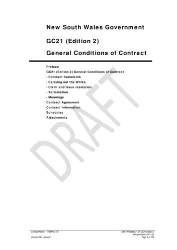
i i.' f, »l«M«'"i*l . 5/ .yI.*,-'fTiN. :;r-y»» Off-Site BackgroundWell approx.500 feetto the S.E.(refer to Figure 5-2) »\ f* ' ?I?i!I!f kGROUNDWATERFLOW DIRECTION MONITORINGWELL LOCATIONCsmp Diesmr S, McKse fe.Ii EXISTING MONITORING WELLNEW MONITORING WELLWELL TO BE ABANDONED2 0 0 FeetPROPERTY BOUNDARYA p p r o x . ScaleFIGURE 4-3NEW MONITORING WELL LOCATIONSRemedial Investigation/Feasibility StudyScorpio Recycling, Inc. Superfund Site, Puerto Rico300572
)f\; ihFiveVinno300573
IIIIIIIIIIIIIIIIRevision.SectionDate September 7. 2004Page5ASectionsField ProcedxiresField procedures for the monitoring well instaUation, DVS and monitoring weU abandonment areoutlined below.5.6 Monitoring Well InstallationThe new locations for the monitoring weU instaUation is presented in Section 4.3 of this QAPPAddendmn No. 1 and shown in Figure 4-3.5.6.3 Procedures for Monitoring Well InstallationProposed monitoring weU design specifications are presented in Figure 5-2.5.6.3.1Borehole InstallationMonitoring weU boreholes will be advanced into bedrock at each location utilizing the procedtuesoutlined below.1. The borehole wiU be driUed through the overburden to bedrock using a driUingmethod that wiU aUow emplacement of the eight-inch carbon steel casing in a 12inch borehole 10 feet into bedrock. At two monitoring weU locations (MW-3A andMW-4A) a twelve-inch diameter carbon steel casing v be grouted into clayapproximately ten feet below groimd siuface (ft bgs).2. Temporary casing may be used to faciUtate driUing while a 12-inch air rotary bit isadvanced. The 12-inch air rotary bit wUl be advanced 10 feet below the bedrocksurface.3. The 12-inch air rotary driU stem wUl be pulled from the borehole, and a nominaleight-inch diameter carbon steel casing wiU be instaUed to the bottom of the existingborehole. The eight-inch casing wiQ be grouted into place using cement/bentonitegrout emplaced via tiemie pipe. As grouting of the casing is ensuing, the temporary12-inch diameter casing wiU be puUed from the borehole. The maximum estimatedeight-inch casing length is 100 feet. The grout wiU be left to ciue for a minimum of 12hours before any other downhole work can proceed.4. DriUing wUl then proceed by advancing an eight-inch air rotary driU bit to depth offirst significant water. For plarming piuposes, a conservative depth to bottom of themonitoring weU is 250 feet bgs.- CDMIScorpio Draft QAPP Addendum.wpdI300574
Revision.SectionDate September 7, 2004Page5 5. The eight-inch diameter borehole wiU be video logged by the Contiactor dvuinginstaUation and after weU development.5.6.3.3M o n i t o r i n g Well InstallationThe bedrock borehole v be converted into a monitoring weU, as shown on Figtue 5-2.Monitoring weUs wUl be constructed using the foUowing specifications:1. WeU construction wUl consist of decontaminated four-inch diameter, schedvde 80PVC riser instaUed within the carbon steel cased eight-inch diameter bedrockborehole. The exact depth of the screen wUl be determined by onsite conditions.The joints wUl be threaded. The screen wUl be schedule 80 PVC, 20 feet in lengthwith 0.020-inch slot size.2. If the selected screen interval is at or near the bottom of the borehole, constructionwUl proceed as described in item 3; otherwise, the portion of the borehole below thebottom of the targeted screen setting must be backfiUed with cement-bentonite groutprior to weU construction. This backfiUing wUl be accomplished in the foUowingmanner:a.b.c.d.e.f.The total depth of the borehole wUl be measmred with a weighted tape.The volume of the borehole to be abandoned wiU be calculated, based on atarget depth of 5-feet below the intended screen bottom. In general, thecalculation wiU be based on the nominal borehole diameter (8-inches).The volume of the tiemie pipe for the length reqioired (including any hosebetween the mud pump and the tiemie pipe) wUl be calculated.A quantity of grout equal to the total volume calcrdated above wUl bemixed. This grout wiU consist of Type II Portland cement. A smaU quantity(no more than 3 to 4 percent by voliune) of piue bentorute may beincorporated in the grout mix.The grout wUl be placed in the borehole by the tremie method. Afterplacement of the grout, the tiemie pipe wUl be removed and the grout wiUbe aUowed to set for a minimiun of 12 hoius.After the grout has set, the depth to the bottom of the hole wiU be measuredwith a weighted tape. If the grout surface is significantly below the targetdepth, additional grout may be added. However, placement of additionalgrout presents significant risk for over fiUing. The field geologist wUl decideif additional grout emplacement is to be attempted.3. The four-inch diameter weU screen and riser shaU be assembled length by lengthabove grade and lowered into the borehole. Riser shaU be instaUed by screwingindividual lengths of riser together, with the already joined lengths or riser/screenCDMScorpio Draft QAPP Addendum.wpd300575
RevisionSectionDate September 7, 2004Page5-3suspended in the borehole. CentiaUzers will be attached to the riser/screen at afrequency of one per 50 feet. The screen shaU be set to the depth specified by theField Geologist.4. A one to two foot layer of filter pack sand will be placed above the bottom of theborehole to the target depth for the bottom of the weU screen. The filter pack wUlconsist of clean, washed, weU rounded sand, 95% siUca, a uniform coefficient of 2,and 90% should be retained from the 0.02-inch slot size screen. The volume of filterpack required v\dU be calculated, based on the length of the interval to be fiUed andthe nominal eight-inch diameter of the borehole. Sufficient time wUl be aUowed tolet the sand settle through the water colimtn before adding additional quantities ofsand. Frequent meastuements will be made with a weighted tape to ensvue thedesired screen zone is not missed. The filter pack wiU be instaUed to three feetabove the weU screen. The depth to the top of the filter pack wUl be measuredbefore installing the very fine sand seal. A three foot thick very fine sand seal wUlthen be set above the filter pack.5. The depth to the top of the very fine sand seal wiU be measured before instaUing thebentonite slurry seal. Six feet of bentonite slurry wUl be instaUed above the filterpack. It is necessary to wait approximately 12 hoxus for the bentonite to hydrate andset. After the bentonite sets, a three foot thick very fine sand seal wdU be placedabove the bentonite slurry. Cement/bentonite grout wUl be used to fiU theremaining annulus above the fine sand seal to a level just below the grovmd surface.The tiemie method wiU be used during the emplacement of grout. The grout wUl beemplaced in two batches of 50 percent each. This entails pumping the first batch ofcement/bentonite grout through a pipe into the borehole from the top of the veryfine sand seal to half way to the siuface and the second batch to the sruface. Noadditional work wUl be permitted adjacent to the monitoring weU for 12 hours whUeeach batch of the grout is curing.6. At the surface, the monitoring weU wUl be completed in one of two ways, eitherwith a steel siuface casing or a flush movmted monitoring weU manhole. The fieldteam leader in consultation with the SM wUl make the decision based on themonitoring weU location and site features. If the surface casing posses a hazard totiaffic, it will be flush mounted with the top of the PVC riser three inches below thesurface. A two-foot by two-foot concrete monitoring weU pad wUl be instaUed.Riser casing caps wiU be provided for each monitoring weU. The protective steelSLuface casing wUl be instaUed such that it fits arovmd the outside of the riser casingand extends approximately six inches above the top of the riser casing. The siufacecement wUl be sloped away from the protective sruface casing diuing finalplacen\ent so as to create a drainage apron. An identification
If you have any questions regrading this addendum, please contact Nancy Rodriguez at (787) 620-5808 or myself at (212) 785-9123. Very truly yours,