Transcription
Energy 172 (2019) 580e591Contents lists available at ScienceDirectEnergyjournal homepage: www.elsevier.com/locate/energyEffects of thermal conductivity and density on phase changematerials-based thermal energy storage systemsBenli Peng a, b, Guanghan Huang b, Pengtao Wang b, Wenming Li b, Wei Chang b,Jiaxuan Ma b, Chen Li b, *abNaval Architecture and Ocean Engineering College, Dalian Maritime University, Dalian, Liaoning, 116026, ChinaDepartment of Mechanical Engineering, University of South Carolina, Columbia, SC, 29208, USAa r t i c l e i n f oa b s t r a c tArticle history:Received 6 September 2018Received in revised form19 December 2018Accepted 28 January 2019Available online 29 January 2019This research systematically studies the impacts of thermal conductivity and density of phase changematerials (PCM) on the characteristics of PCM-based thermal energy storage systems (TES). We showthat the eutectic PCM, owing to its high thermal conductivity, has more stable temperature evolutionthan that of paraffin wax during both heat charging and discharging processes. The paraffin wax has anenhanced charging rate, when the heat is applied at the bottom, as a result of convection driven by theobvious temperature-dependent density of liquid paraffin wax. The convection and orientation effectsare significant in the charging process of paraffin wax, but insignificant for eutectic PCM, which arefurther confirmed by visualization and numerical studies. Specifically, a gap forms between the coveredplate wall and the solid paraffin wax after discharging process. This gap significantly inhibits the chargingprocess in a heat charging and discharging cycle. We also observed that the charging efficiency of theparaffin wax is substantially reduced by its high contact thermal resistance, which is 2e3 orders ofmagnitude higher than that of eutectic PCM. This shows that rapid thermal energy charging/dischargingrates, a highly desirable stable working temperature, and orientation-insensitivity of TES can be achievedusing PCM with a high thermal conductivity and a temperature-independent density. 2019 Elsevier Ltd. All rights reserved.Keywords:Phase change materialsCharging/discharging performanceThermal conductivity effectDensity and orientation effect1. IntroductionPhase change materials (PCM) with a low melting point havebeen extensively employed in thermal energy storage systems(TES) [1e4], thermal management of electronics [3], building [5e7],heat recovery [8,9], heat pumps [10], electric vehicles [11], dieselengines [12], batteries [13e16] and spacecraft [17]. Optimizedcharging/discharging performances with stable temperature evolutions, small temperature differences, short charging/dischargingtime, and high charging/discharging efficiencies are highly desirable for PCM in these applications. However, the PCM performancecan be greatly affected by thermal conductivity. PCM with a lowthermal conductivity, such as paraffin wax, hydrated salts, and fattyacids, have been widely employed in TES. Numerous techniqueshave been developed to improve their thermal conductivities, suchas embedding highly conductive nanomaterials [18e21], particles[19] and fins [22e24]. The thermal conductivities of paraffin can beenhanced up to 48% and 60% by adding paraffin-nanomagnetitecomposites (PNMS) with weight concentrations at 10% and 20%[20], respectively, which accordingly increases the cost of theparaffin by 20e40%. However, the charging rate was still low evenafter integrating three additional fins on the hot wall [22]. The finconfigurations to enhance heat charging/discharging processesunder different conditions were also numerically analyzed [24].Similar observations have been reported using other filling materials, including carbon nano tubes (CNT) [21] and carbon fibers[18,25]. The charging rate was fundamentally limited by the slightlyenhanced thermal conductivities and large interfacial thermalresistance between the PCM and filling materials.The charging/discharging processes of PCM have been extensively investigated experimentally [10,22,24,26e30], theoretically[31] and numerically [32,33]. Wang et al. [29] experimentally* Corresponding author. Department of Mechanical Engineering, University of South Carolina, Columbia, SC, 29208, USA.E-mail address: li01@cec.sc.edu (C. 60-5442/ 2019 Elsevier Ltd. All rights reserved.
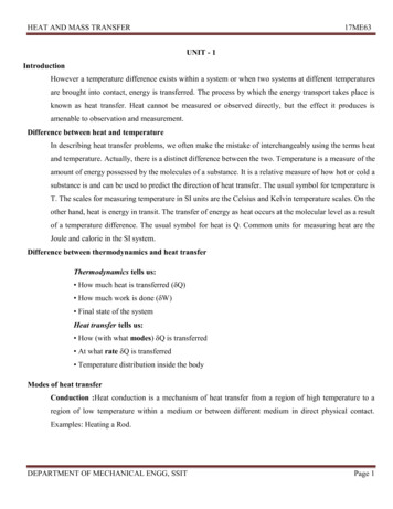
B. Peng et al. / Energy 172 (2019) 580e591NomenclaturecphhsfkmpQqTVspecific heat capacity (J kg 1 K 1)height (m)latent heat of fusion (kJ kg 1)thermal conductivity (W m 1 K 1)mass (kg)heating power (W)heat (J)heat transfer rate (W)temperature ( C)volume (m3)Greek Symbolsqtime (s)rdensity (kg m-3)εcharging efficiencydemonstrated that the charging rate of the capsule employing threePCM components was significantly enhanced compared toemploying single PCM component. However, the mechanism wasnot discussed in the study. Arefeh [32] numerically showed that theconduction heat transfer dominated at the beginning, then theconvection heat transfer started working and improved thecharging process when the phase change occurs. On the other hand,the experiment conducted by Kandasamy et al. [3] indicated thatthe orientation effect was not significant in practical applications.Yang et al. [31] analyzed the charging/discharging processes andprovided a theoretical guidance for applications of three PCM TESin a solar thermal power system. Ramalingam et al. [28] investigated the melting and solidification of paraffin wax in a concentrictube PCM TES. Naidu et al. [27] analyzed the charging and discharging process of paraffin wax and a small temperature vibrationwas found in the charging process. Again, the mechanism was notdiscussed. Moreover, the effect of thermal conductivity and densityof PCM on the charging/discharging rates and temperature evolutions are still unclear. The charging and discharging processes ofdifferent PCM need to be systematically investigated.This research studies the effect of thermal conductivity anddensity of PCM on the charging/discharging processes of PCMbased TES, and provides a guide to select an appropriate PCM forpractical applications. A eutectic PCM and a paraffin wax, with highthermal conductivity ratio and similar volumetric energy density,were selected in this study [4,34]. An experimental system wasdesigned and built. The temperature evolutions measurement,visualization experiment and numerical simulation are performed.The temperature evolutions of two different PCM in charging/discharging under various thermal loads were characterized. Themechanism of the charging processes of eutectic PCM and paraffinwax were also analyzed through comparing contact thermal resistances. The convection and orientation effects during thecharging/discharging process of PCM were visualized. A short solidslice with small density of liquid paraffin wax was used as a tracerparticle to visualize and track the velocity of the liquid paraffin waxduring the metling process. A numerical melting/solidificationmodel was established using the two dimensional (2D) enthalpyporosity method [35e38] to verify the orientation effect (i.e., effect of natural convection) in the charging process of paraffin wax.An experiment was conducted to minimize gravity impacts on PCMmelting by heating samples from the top surface. A cycling experiment including charging the PCM in the top heating condition,discharging the PCM and subsequently charging the PCM in the top581heating condition was also carried out to confirm the effect ofdesnity on parafifin wax performance.2. ExperimentsA schematic of the experimental system is shown in Fig. 1. Itconsists of a sample chamber, a test samples, a heating system, avoltage regulator, and a data acquisition system. The chamber(45.0 mm 38.0 mm 71.0 mm) is made of polysulfone (McMaster, k ¼ 0.26 W m 1 K 1). A hole with a diameter of 12.7 mm anddepth of 61.0 mm was drilled in the center of the block. A copperrod with a diameter of 12.7 mm and length of 30.0 mm wasmounted at the bottom section of the hole. A hole with a diameterof 6.35 mm was drilled in the center of the copper rod to house acartridge heater.A voltage regulator (ranging from 0.0 to 120.0 V) is used toadjust input heating power from 4.34 to 21.01 W. Five T-typethermocouples (Omega, www.omega.com, USA) are installed in theholes along the sample chamber. The distance between twoneighboring holes is 6.0 mm. The top of the sample chamber iscovered by a copper cap with a silicone gasket. The chamber isinsulated by mineral wools with thermal conductivity of 0.04 W m 1 K 1 (Thermafiber, Inc, www.thermafiber.com, USA,Thermafiber FRF). When a discharging process is carried out, thetop of the chamber is exposed to air. The stored heat is released toambient by natural convection. The PCM temperatures aremeasured by five T-type thermocouples with an uncertainty of 0.25 C. The effective height of the cylindrical PCM sample is24.0 mm which is the same as the highest position of the thermalcouple. The effective volume of PCM is 3.0387 10 6 m3. Theproperties of the eutectic PCM (Bi50Pb26.7Sn13.3Cd10) and paraffinwax are specified in Table 1. The volumetric energy density includesboth latent heat and sensible heat. The temperature difference incharactering the sensible heat is set from room temperature of 20 C to a terminal temperature of 80 C. (The temperature difference between 20 C to the melting point is used to calculate thesensible heat volumetric energy density in the solid state of PCM,and the temperature difference between melting point to 80 C isapplied to calculate the sensible heat volumetric energy density inthe liquid state of PCM.)The charging processes of PCM and the performances weretested under seven thermal loads including 4.34 W, 6.25 W, 8.51 W,11.11 W, 14.06 W, 17.36 W and 21.01 W. Moreover, the other twoworkloads (i.e., 5.45 W for eutectic PCM and 7.5 W for paraffin wax)were applied to verify the orientation effect in the charging process.The sample was heated up from the room temperature toapproximately 80 C in the charging process. Then the insulationlayer at the top of the copper cap was removed for its dischargingprocess. Data was recorded in both charging and discharging processes. The effect of the buoyant force (induced the natural convection) on the charging and discharging processes wereinvestigated by heating PCM from the bottom and top (orientationeffect). The top heating can suppress the natural convection. Allexperiments were repeated twice under the same workingcondition.A visualization study on the charging and discharging processesof the paraffin wax was conducted in a transparent glass cylinder,using a high-speed camera (Phantom v7.3) equipped with a macrolens(SigmaEx-DGMACRO-105 mm1:2.8,depthoffield:10e20 mm). A short solid slice with nearly identical density ofliquid paraffin wax was used as a tracer particle to demonstrate theflow direction in the liquid PCM during the charging process. Theframe rate of the high-speed camera applied in the experiment is10 frames per second. The discharging process of eutectic PCM wasalso visualized in a metal cylinder for comparisons.
582B. Peng et al. / Energy 172 (2019) 580e591CapGasketThermocouplesSampleh4 24mmSampleChamberh3 18mm2423Copper Rodh2 12mm22CartridgeHeaterh1 6mmHeater Wires21h0 0mm(a)(b)Fig. 1. (a) Schematic of the experimental system and (b) the thermocouples installation in the PCM sample.3. Data reductionThe total charging energy of a PCM consists of sensible heat Q1(for the solid state), the latent heat of fusion Q2, and the sensibleheat Q3 (for the liquid state) with correspondingly charging time q1,q2 and q3 in three stages. Therefore, three charging stages aredefined as following. Charging the solid PCM is the first stage,where temperature increases from the initial temperature 20 C tothe melting point. The melting process of PCM is the second stageð Tmeltingqeff;av ¼Qtotalqcharging¼TinitialmPCM;s cpPCM;s dT þ mPCM hfusion þqchargingð TterminalTmeltingand completed until the PCM completely melted. Charging theliquid PCM is the third stage, where the temperature increases fromthe completely melted PCM to the terminal temperature 80 C. Thedischarging process is a reverse process to the charging process.The total heat absorbed by the PCM during the charging process,equals to the mass of the PCM times the volumetric energy densityof the PCM, is written as [41,42],TmeltingðQtotal ¼mPCM;s cpPCM;s dT þ mPCM hfusionTinitialTterminalðþmPCM;l cpPCM;l dT(1)Tmeltingwhere mPCM is the mass of the PCM, and mPCM ¼ rPCMVPCM, cpPCM isthe specific heat capacity of PCM, hfusion is the latent heat of fusion,Tmelting, Tinitial and Tterminal are the melting point, initial temperatureand terminal temperature of a PCM, respectively. The eutectic PCMand paraffin wax have a melting point 70.0 C, the initial temperature of 20.0 C and the terminal temperature of 80.0 C. Thesubscripts s and l represent the solid and liquid phases,respectively.The average effective charging rate is calculated by,mPCM;l cpPCM;l dT(2)where qcharging is the total charging time.4. Results and discussions4.1. Charging process4.1.1. Temperature evolutionsThe comparisons of the temperature evolutions at differentheights during the charging processes of eutectic PCM(Bi50Pb26.7Sn13.3Cd10) and paraffin wax, with a heating power of8.51 W from the bottom, are shown in Fig. 2.It clearly demonstrates that the temperature change rate of theeutectic PCM (Bi50Pb26.7Sn13.3Cd10) in all measured locations sharesa similar trend during the charging process and decreases sharplywhen the melting occurs. The temperature difference between twoTable 1Major properties of the PCM used in this study in room temperature.PropertiesMaterialsMelting PointTmelt ( C)Bi50Pb26.7Sn13.3Cd10 70Paraffin Wax69e73Latent Heat hsf(kJ kg 1)Density r(kg m 3)Specific Heat Capacity(kJ kg 1 K 1)Thermal Conductivity kPCM(W m 1 K 1)Volumetric energy density(MJ m 3)39.8200e220 [39]9580 900 [40]0.1842.19e2.9 [39]18.0 0.25487.05 326.43
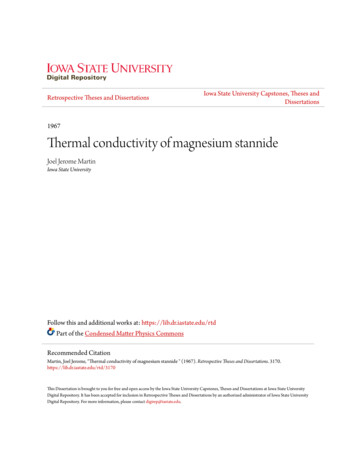
B. Peng et al. / Energy 172 (2019) 580e59190PCM:Bi50Pb26.7Sn13.3Cd10; Heater power 8.51W90(a)Height 0mmHeight 6mmHeight 12mmHeight 18mmHeight 24mm5040Temperature (oC)60Bottomheating30Melting point70Melting point70Temperature (oC)(b)PCM: Paraffin wax; Heat power 8.51W8080605040302020105830110 220 330 440 550 660 770 880 990 11000Height 0mmHeight 12mmBottomheating100200400600800Height 6mmHeight 18mmHeight 24mm100012001400Time (s)Time (s)Fig. 2. Temperature evolutions during a charging process for different PCM (heating power ¼ 8.51 W (a) Bi50Pb26.7Sn13.3Cd10, melting point: 70 C, keutectic ¼ 18 W m 1 K 1; (b)Paraffin wax, melting point: 69 Ce73 C, kwax ¼ 0.25 W m 1 K 1, at the bottom heating condition).neighboring positions is consistent and nearly identical in thecharging process of the eutectic PCM (Bi50Pb26.7Sn13.3Cd10), thetemperature distribution at the same charging time is stable and notemperature fluctuations were observed during the whole process.This indicates that conductive heat transfer dominates the wholecharging process of the eutectic PCM.The heating process is non-uniform for the paraffin wax. Thetemperature at 0 mm increases rapidly, but it presents differenttrends between 6 mm and 24 mm. Typically, the temperature at24 mm remains at 20 C (i.e. the room temperature) after 400 s.However, the corresponding temperature for eutectic PCM is up to50 C. The temperature at 6 mm in eutectic PCM is up to 65 C whenthe temperature of the heating surface reached its melting point( 70 C), but the corresponding temperature in paraffin wax is only25 C. This huge difference in temperature is induced by theextreme lower thermal conductivity of the paraffin wax and a muchlarger contact thermal resistance between the paraffin wax and theheating surface. Because a low thermal conductivity strongly impedes the heat transfer in the paraffin wax, which induces the hugetemperature difference between the two neighboring positions inthe paraffin wax. The high contact thermal resistance significantlyimpedes the heat transfer from the heating surface to the solidparaffin wax thus induces the huge temperature difference between the heating surface and the paraffin wax. Moreover, thecontact thermal resistance is also dependent of the thermal conductivity of the PCM as discussed in the following section.4.1.2. Effects of contact thermal resistanceThe contact thermal resistances between the PCM and theheating surface before melting were analyzed. It can further explainthe huge difference of heat transfer performance between thesetwo PCM. The effective heat flux for the PCM in charging process iscalculated with an assumption of one dimensional heat conductionin the cylindrical [43], written as 4 PT Ti h hiq1 ¼ kPCM i¼14 Ph hi 2(3)i¼1where h is the installation height of the thermocouple, T is themeasured temperature, the average temperature T and averageheight h in Eq. (3) are calculated as,4PTi4PhiT ¼ i¼1 ; h ¼ i¼144(4)The effective heat flux is obtained by the overall thermal resistance between the heating surface and PCM. The effective heat fluxthrough the PCM can be calculated as,Ts T q1 ¼ Rc þ k h(5)PCMThe contact thermal resistance, Rc, is calculated as,Rc ¼Ts Th q1kPCM(6)The contact thermal resistance and the effective heat flux between the heating surface and the PCM about eutectic PCM andparaffin wax are compared in Fig. 3.Fig. 3 illustrates that the effective heat flux in the highlyconductive eutectic PCM (from 6 kW m 2 to 20 kW m 2) is muchhigher than that of the paraffin wax (from 28 W m 2 to 100 W m 2). The contact thermal resistance between the heatingsurface and the paraffin wax is 2e3 orders of magnitude larger thanthat of the eutectic PCM-heating surface interface.4.1.3. Effects of natural convectionFor the paraffin wax, the temperature difference between thetwo neighboring measurement positions, prior to its melting pointof 70 C, is much larger than that of eutectic PCM, as shown in Fig. 2.It is consistent with a lower thermal conductivity and a highercontact thermal resistance of paraffin wax. The temperature in theparaffin wax increases more rapidly after the temperature exceedsits melting point. Temperature fluctuations up to 50 C wereobserved during the charging process in the paraffin wax. Theselarge temperature fluctuations are different from the very smalltemperature variations experimentally observed by other researchers [27]. The temperature profile in paraffin wax is substantially different from that of the eutectic PCM, which have notbeen reported in previous studies [44e46]. This is due to the significant density difference in solid and liquid phases [27] and thetemperature-dependent density of the liquid paraffin wax [47]. Thesolid paraffin wax with a relatively higher density descends toward
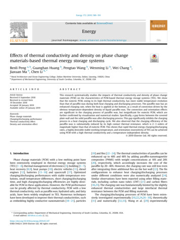
(a)4.020Eutectic18163.5143.0Effective heat flux2.512102.081.5Contact thermal resistance1.0640.5200.015 20 25 30 35 40 45 50 55 60 65 70 75o1.61.4(b)98Paraffin waxContact thermal resistance841.2701.0560.8420.6280.4Effective heat flux0.2Effective heat flux (W m-2)4.5Effective heat flux (kW m-2)Contact thermal resistance (m2 K W-1)B. Peng et al. / Energy 172 (2019) 580e591Contact thermal resistance 104 (m2 K W-1)5841400.015 20 25 30 35 40 45 50 55 60 65 70 75Surface temperature (oC)Surface temperature ( C)Fig. 3. Contact thermal resistance between PCM and copper rod and the effective heat flux in PCM. (a) eutectic PCM, (b) paraffin wax.Bubblet t0t t0 2st t0 4st t0 6st t0 7st t0 8st t0 9st t0 10st t0 11st t0 12sFig. 4. The bubble as highlighted by blue color and the natural convection during the charging process of the paraffin wax. A piece of solid slice was moving in clockwise directiondue to the natural convection as highlighted by red color.the liquid paraffin wax, and the temperature-dependent density ofthe liquid paraffin wax induces strong natural convection (clockwise direction flow marked by the solid slice in Fig. 4) and enhancesheat transfer as indicated by large temperature fluctuations. Thisstrong natural convection during the paraffin wax melting processis clearly observed in the visualization study, as shown in Fig. 4. Thevisualization is conducted in a glass cylinder and using a highspeed camera (10 frames per second). The natural convection isnot found in the charging process of the eutectic PCM, and the glasscylinder is broken during the charging process of the eutectic PCM.It is due to its high density and high stress to the glass cylinder,herein, no visualization results about the charging process ofeutectic PCM were recorded. Moreover, some small air bubbles arealso observed in the liquid paraffin wax, highlighted by a blue circleshown in Fig. 4. These bubbles may come from the air trappedbetween the glass cylinder and the solid paraffin wax and/or in thesolid paraffin wax during the filling process.The liquid paraffin wax at high temperature is driven by thebuoyant force, which may heat or even melt the solid paraffin wax,leading to a temperature spike [48]. Then the liquid paraffin wax iscooled down by the melting of solid paraffin, resulting in a sharptemperature drop as highlighted in Fig. 2 (b). The naturalconvection effect in the charging process of paraffin wax is clearlyrepresented by the flow field in numerical simulation, as shown inFig. 5 (a) (at the bottom heating condition) and Fig. 5 (b) (at the topheating condition). The similar phenomena have been numericallypredicted with a melting/solidification model using the enthalpyporosity method [35e38]. The effective heating power applied inthe numerical simulation is 1.0 W. However, the flow fields in thecharging process of eutectic PCM is not shown here because there isno velocity field in the liquid eutectic PCM during the chargingprocess. Moreover, the temperature contours during the chargingprocesses of eutectic PCM and paraffin wax in different heatingconditions (i.e. the bottom heating condition and the top heatingcondition) are predicted, which clearly verify the non-existance ofnatural convection in the liquid eutectic PCM during the chargingprocess.When the paraffin wax is heated from the bottom, a vortex flowis developed in the melted liquid paraffin wax (q 200 s), as shownin Fig. 5 (a). But such a vortex flow is not observed in the liquidparaffin wax when heating the sample from the top, as shown inFig. 5 (b). This clearly verifies that the heating orientation ofparaffin wax can significantly affect its charging performance. Themelting height of the paraffin wax under bottom heating condition
B. Peng et al. / Energy 172 (2019) 580e591 100s 200s585 400s 1000s 400s 1000s(a) Bottom heating 100s 200s(b) Top heating, 50 magnificationFig. 5. Flow field in charging process of paraffin wax at different heating styles ((a) bottom heating, (b) top heating with 50 magnification), the effective heating power is 1.0 W.is about 20 mm, which is much higher than that under top heating(about 13 mm at the charging time q ¼ 1000 s). However, naturalconvection is not observed on eutectic PCM, because its densities insolid and liquid phases are nearly identical. Although the thermalconductivity ratio between the eutectic PCM and paraffin wax is 72,the total charging time of paraffin wax is only 33%e86% longer thanthat of eutectic PCM when the heat load ranges from 4.34 W to21.01 W. This is because the intense and strong natural convectionsignificantly enhances the charging rate and obviously shortens thetotal charging time of paraffin wax.The absence of nature convection in the charging process ofliquid eutectic PCM can be further verified from the numericalpredicted temperature contours. The temperature contours duringthe charging processes of eutectic PCM and paraffin wax at differentheating conditions (bottom heating condition and top heatingcondition) are respectively shown in Fig. 6 and Fig. 7.When heated from the bottom, the temperature contour issmooth and flat before melting occurs in the bulk paraffin wax,except for the positions that are very near the heating surface(q ¼ 100 s), as shown in Fig. 6(a). However, after melting occurs inthe paraffin wax with a distance from the heating surface, thenatural convection, induced by the temperature-dependent densityof paraffin wax significantly disturbs the temperature contours. Thetemperature contour distorts (q ¼ 400 s), which agrees well withthe present of vortex flow as shown in Fig. 5 (a). The natural convection becomes more intense and complicated along with morecharging time (q ¼ 1000 s), resulting in more irregular temperaturecontour. It is also obviously found in the flow field (three vortexes)shown in Fig. 5 (a). However, for the top heating, the temperaturecontours remain smooth and flat during the charging process ofparaffin wax, as shown in Fig. 6 (b). It indicates that there is nonatural convection in the paraffin wax, and conductive heattransfer dominates the charging process. Moreover, the naturalconvection causes the temperature of heating surface much lowerunder the bottom heating than that under the top heating. Thisverifies the significant benefits of the natural convection to thecharging process at the bottom heating.Different from the temperature contours in the charging processof paraffin wax shown in Fig. 6, the temperature contours ofeutectic PCM are smooth and flat with heating from the bottom andthe top cases in the whole charging process as illustrated in Fig. 7.The same temperature contour clearly illustrates no natural convection occurring in the charging process of eutectic PCM.Conductive heat transfer dominates the charging process.4.1.4. Effects of orientationThe experimental and simulation results of orientation effectson the temperature evolutions during the charging processes ofthese two PCM are shown in Figs. 8 and 9, respectively. Other tworandom heating powers (5.45 W for eutectic PCM and 7.5 W forparaffin wax) are applied in the experiment to verify the orientation effects. The almost overlapped temperature evolution curvesunder bottom heating and top heating clearly demonstrate that thetemperature evolutions are independent of the orientation for theeutectic PCM samples both in experimental and numerical study(shown in Fig. 8 (a) and Fig. 9 (a) respectively). It indicates thatconductive heat transfer dominates the melting process of theeutectic PCM. which can be further verified by the temperaturecontour shown in Fig. 7.Unlike eutectic PCM, the temperature evolutions during the
586B. Peng et al. / Energy 172 (2019) 20x (m)70.50112.00.020153.595.75y (m)y (m)0.000-0.006 -0.003 0.000 0.003 0.00629.0045.250.015121.079.06102.70.0300.02555.44 100sx (m)20.000.02531.810.005164.00.000-0.006 -0.003 0.000 0.003 0.006(a) Bottom heating20.0090.88148.1151.50.0300.010132.30.005x (m)67.25100.5116.40.000-0.006 -0.003 0.000 0.003 0.006x 000-0.006 -0.003 0.000 0.003 146.30.0100.010278.0171.5196.80.005114.5 400s0.000-0.006 -0.003 0.000 0.003 0.006x (m)37.0052.8869.31y (m)y (m)67.250.02536.4455.440.015 1000s20.00y (m)0.025 400s20.00y (m) 100s319.50.005222.0 1000s361.00.000-0.006 -0.003 0.000 0.003 0.006x (m)(b) Top heatingFig. 6. The temperature evolution in charging process of paraffin wax at different heating styles ((a) bottom heating, (b) top heating), the effective heating power is 1.0 W.charging process of the paraffin wax are highly dependent on theorientation as displayed in Fig. 8 (b), but such significant differencein the charging times has not been observed when the heating fromhorizontal, vertical, or slanted orientations were reported by Kandasamy et al. [3]. When heating from the bottom, natural convection plays a significant role during the melting process and shortensthe total charging time. When heating from the top, it takes muchlonger to heat the whole paraffin wax sample after minimizing theeffect of natural convection. The numerical results show that thenatural convection can significantly shorten the charging time ofparaffin wax, as shown in Fig. 9 (b). It further validates that naturalconvection can significant enhance charging process [49,50] andshortern charging time. Therefore, the benefits of the orientationeffect in the charging process of paraffin wax needs to be considered in practical applications.4.1.5. Charging time and effective charging rate (under bottomheating)The PCM charging time of each stage at various heating powersis shown in Fig. 10 for the eutectic PCM and the paraffin wax,respectively. It indicates the charging time on the second stage (i.e.the melting process) takes the longest time for two PCM because ofthe phase change. The first and third stages take a very short timedue to the absent of phase change, where only sensible heattransfer plays a role. The charging time for each stage reduces withincreasing heating power. The charging time on the second stage ofparaffin wax is 2 times longer than that of the eutectic PCM. This isalso primarily a collective effect of its lower thermal conductivityand stronger natural convection.Fig. 11 shows the total charging time and the correspondingaverage effective charging rate of eutectic PCM and paraffin waxfrom 20 C to 80 C at various heating powers. Consistently, thetotal charging time of the paraffin wax is much longer than that ofthe eutectic PCM. Although the thermal conductivity of the paraffinwax is 1/72 of eutectic PCM, the charging rate of paraffin wax isenhanced by the strong natural convection during the chargingprocess, which greatly shortens its total charging time. The totalcharging time of the paraffin wax is only 1.33 to 1.86 times longerthan those of the eutectic PCM for heating power in a range of4.34e21.01 W. This is much less than the thermal conductivity ratio. The average effective charging rate of the
than that of paraffin wax during both heat charging and discharging processes. The paraffin wax has an . heat recovery [8,9], heat pumps [10], electric vehicles [11], diesel engines [12], batteries [13e16] and spacecraft [17]. Optimized . (Omega,www.omega.com,USA)areinstalledinthe holes along the sample chamber. The distance between two