Transcription
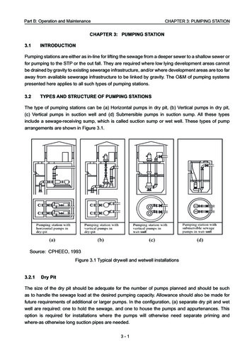
Part B: Operation and MaintenanceCHAPTER 3: PUMPING STATIONCHAPTER 3: PUMPING STATION3.1INTRODUCTIONPumping stations are either as in-line for lifting the sewage from a deeper sewer to a shallow sewer orfor pumping to the STP or the out fall. They are required where low lying development areas cannotbe drained by gravity to existing sewerage infrastructure, and/or where development areas are too faraway from available sewerage infrastructure to be linked by gravity. The O&M of pumping systemspresented here applies to all such types of pumping stations.3.2TYPES AND STRUCTURE OF PUMPING STATIONSThe type of pumping stations can be (a) Horizontal pumps in dry pit, (b) Vertical pumps in dry pit,(c) Vertical pumps in suction well and (d) Submersible pumps in suction sump. All these typesinclude a sewage-receiving sump, which is called suction sump or wet well. These types of pumparrangements are shown in Figure 3.1.Source: CPHEEO, 1993Figure 3.1 Typical drywell and wetwell installations3.2.1Dry PitThe size of the dry pit should be adequate for the number of pumps planned and should be suchas to handle the sewage load at the desired pumping capacity. Allowance should also be made forfuture requirements of additional or larger pumps. In the configuration, (a) separate dry pit and wetwell are required: one to hold the sewage, and one to house the pumps and appurtenances. Thisoption is required for installations where the pumps will otherwise need separate priming andwhere-as otherwise long suction pipes are needed.3-1
Part B: Operation and MaintenanceCHAPTER 3: PUMPING STATIONIt is typically used to pump large volumes of raw sewage, where uninterrupted flow is criticaland sewage solids could clog suction piping. It is also used to pump solids in pipe galleriesbetween digesters or other solids-handling equipment. While construction costs may behigher and a heating, ventilation and cooling system is necessary when installed belowthe floor level, this configuration is best for O&M activities because operators can see andtouch the equipment.3.2.2Suction Sump or Wet WellSewage sump is a compartment or tank in which sewage is collected. The suction pipe of apump may be connected to the wet well or a submersible pump may be located in the wet well.Sewage sump design depends on the type of pumping station configuration (submersible ordry well) and the type of pump controls (constant or variable speed). Wet wells are typicallydesigned to prevent rapid pump cycling but small enough to prevent a long detention time andassociated odour release.Sewage sumps should always hold some level of sewage to minimise odour release. Bar screensor grinders are often installed in or upstream of the wet well to minimise pump clogging problems.Instead of manually operated screens at the bottom, which requires the staff to get down into thescreen sump, it is better to install mechanical bar screens, which can automatically remove thescreenings and lift the same safely above the ground level. There can also be two such screens oneafter the other for coarse screenings and fine screenings. This will require rectangular channels tomaintain longitudinal non-turbulent linear flow.3.2.3Lift StationsIn general, lift stations are invariably used in gravity sewer network where depth of cut ofsewers poses a problem in high water prone areas. The procedure is to sink a wet well on the roadshoulder or an acquired plot after the shoulder and divert the deeper sewer there. The submersiblepump will lift the sewage and discharge it to the next on line shallow sewer. This is a very usefulpractice in such locations.Equipment located in the wet well should be minimized, including suction and discharge valves,check valves, or other equipment that require routine, periodic maintenance. This equipment can belocated in separate and suitable dry pits located adjacent to the wet well to facilitate accessibility andmaintenance for the operator.3.2.4Operation and MaintenancePumping machinery is subjected to wear & tear, erosion and corrosion due to its nature offunctioning, and therefore it is vulnerable to failures. Generally, failures or interruptions are mostlyattributed to pumping machinery rather than any other component. Therefore, correct operationand timely maintenance and upkeep of pumping stations and pumping machinery are of vitalimportance. Sudden failures can be avoided by timely inspection, follow up actions on observations ofinspection and planned periodical maintenance. Downtime can be reduced by maintaining inventoryof fast moving spare parts. Obviously due attention needs to be paid to all such aspects for efficientand reliable functioning of pumping machinery.3-2
Part B: Operation and Maintenance3.2.4.1CHAPTER 3: PUMPING STATIONOperation of the PumpsThe following points should be observed while operating the pumps.A. Dry running of the pumps should be avoided.B. Centrifugal pumps if installed with negative suction should be primed before starting.C. Pumps should be operated only within the recommended range of the head-dischargecharacteristics of the pump. If pump is operated at a point away from duty point, the pump efficiency normally reduces. Operation near the shut-off point should be avoided, as it causes substantial recirculationwithin the pump, resulting in overheating of sewage in the casing and consequently,overheating of the pump.D. As far as possible positive suction is to be provided to avoid priming during design itself.E. Voltage during operation of the pump-motor set should be within 10 % of the rated voltage.Similarly, current should be below the rated current shown on the name plate of the motor.F. When parallel pumps are to be operated, the pumps should be started and stopped with a timelag between two pumps to restrict change of flow velocity to minimum and to restrict the dip involtage in the incoming feeder and should be adequate to allow the pump head to stabilise.G. When the pumps are to be operated in series, they should be started and stopped sequentially,but with minimum time lag. Any pump next in sequence should be started immediately after thedelivery valve of the previous pump is even partly opened. Due care should be taken to keepopen the air vent of the pump next in sequence, before starting that pump.H. The stuffing box should allow a drip of leakage to ensure that no air passes into the pump and thatthe packing gets adequate wetness for cooling and lubrication. When the stuffing box is sealedwith grease, adequate refill of the grease should be maintained.I. The running of duty pumps and standby pumps should be scheduled so that no pumpremains idle for a long period and all pumps are in ready-to-run condition. Similarly, the runningschedules should be ensured so that all pumps do not wear equally needing simultaneousoverhaul.J. If any undue vibration or noise is noticed, the pump should be stopped immediately and the causefor vibration or noise should be checked and rectified.K. Generally, the number of starts per hour shall not exceed four. Frequent starting and stoppingshould be avoided as each start causes overloading of motor, starter, contactor and contacts.Although overloading lasts only for a few seconds, it reduces the life of the equipment.L. Troubles in a sewage pumping station can be mostly traced to the design stage itself. This isall the more true when too much grit is likely to come into the sewage pumping stations fromsewage at monsoon time, which is difficult to handle. Hence, sewers should not collect anystorm water.3-3
Part B: Operation and Maintenance3.2.4.2CHAPTER 3: PUMPING STATIONUndesirable OperationsThe following undesirable operations should be avoided:A. Operation at higher headA pump should never be operated at a head higher than the maximum recommended headotherwise such operation may result in excessive recirculation in the pump, and overheating of thesewage and the pump. Another problem that arises if a pump is operated at a head higher than therecommended maximum head is that the radial reaction on the pump shaft increases causingexcessive unbalanced forces on the shaft, which may cause failure of the pump shaft. As a useful guide,appropriate marking should be made on the pressure gauge. Efficiency at a higher head is normallylow and such an operation is also inefficient.B. Operation at lower headIf a pump is operated at a lower head than the recommended minimum head, the radial reactionon the pump shaft increases causing excessive unbalanced forces on the shaft, which may causepremature wear of bearings and possibly shaft failure if persisted. As a useful guide appropriatemarking should be made on both pressure gauge and ammeter. Efficiency at a lower head isnormally low, hence such an operation is inefficient. In such cases, it is advisable to throttle thedelivery side valve to create more head to work within safe head. This will also reduce the power. Ifthis is a design flaw additional head has to be created at tail end by elevating the delivery. However,these are not energy efficient solutions; change of impeller to suit the actual head is the solution.C. Operation on higher suction liftIf a pump is operated on suction lift higher than the permissible value, pressures at the eye of impellerand the suction side fall below vapour pressure. This results in flashing of sewage into vapour. Thesevapour bubbles collapse during passage, resulting in cavitation in the pump, causing pitting on thesuction side of impeller and casing, and excessive vibrations. In addition to mechanical damage dueto pitting, pump discharge also reduces drastically. Typical damage to impeller and sometimes to thecasing is shown in Figure 3.2.Source: Figure 3.2 Typical Cavitation Damage of an Impeller3-4
Part B: Operation and MaintenanceCHAPTER 3: PUMPING STATIOND. Operation of the pump with low submergenceMinimum submergence above the bell-mouth or foot-valve is necessary to prevent entry ofair into the suction of the pump, which gives rise to the vortex phenomenon, causing excessivevibration, overloading of bearings, reduction in discharge and in the efficiency. As a useful guide, thelowest permissible sewage level should be marked on the water level indicator. Usually the pumpmanufacturer indicates the minimum height of submergence. In the case of submersible pumps, theminimum depth is needed to ensure cooling of the motor while running.E. Operation with occurrence of vorticesIf vibration continues even after taking all precautions, vortex may be the cause. Vortex should bestopped by using anti vortex fittings as described in chapter 4 of Part A of the manual:A well-planned maintenance programme for pumping systems can reduce or prevent unnecessaryequipment wear and downtime. (The following maintenance information applies to both sewage andsolids pumping systems.)The following is a maintenance checklist for a basic pumping-station: Check the wet well level continuously (whenever necessary). Record each pump’s “run time” hours (as indicated on the elapsed-time meters) at least once ina day and confirm that the pumps’ running hours are equal. Ensure that the control-panel switches are in their proper positions. Ensure that the valves are in their proper positions. Check for unusual pump noises. At least once a week, manually pump down the wet well to check for and to remove debris thatmay clog the pumps. Inspect the float balls and cables and remove all debris to ensure that they operate properly.Twisted cables are to be released that may affect automatic operations. If a pump is removed from service, adjust the lead pump selector switch to the number thatcorresponds to the pumps remaining in operation. (This allows the lead pump levels to govern theoperating pump’s starts and stops.).3.2.4.3Piping and Appurtenance MaintenanceProperly maintaining pumping-station pipelines and other appurtenances can minimize pump loads.Excessive head losses on either the suction or the discharge side of a pump can increase energyuse and the wear rate and consequently, the O&M costs. Excessive head losses also may lead toprocess or treatment problems because solids move slower, so the proper solids balance is notmaintained. Operators can monitor head losses by routinely checking the pressure gauges on bothsides of the pumps.3-5
Part B: Operation and MaintenanceCHAPTER 3: PUMPING STATIONWhen operators notice excessive head losses (indicated by a pressure drop on the suction sideof the pump or an increase in pressure on the discharge side), they should determine whether thelosses are a result of partial clogging, a restriction somewhere in the line, or materials built up onthe pipe wall. To find clogs, operators should start by checking the pressure at various points in thesuction and discharge piping, and look for spots with abrupt head loss (such as valves or otherconstrictions). If something is caught in a valve or other appurtenance, the operator should stop thepump and physically open out the valve head and remove the blockage. In smaller pumps, it is easierto remove the entire valve, disassemble and remove the blockage, reassemble and refit. During suchtime, other pumps shall be run. Scum build-up problems typically are addressed via source control(for instance, by installing grease traps in the collection system at locations suspected or known togenerate grease, such as restaurants, etc.).3.3GATES, VALVES AND ACTUATORS3.3.1Sluice GateA sluice gate (Figure 3.3) is traditionally a wooden or metal plate, which slides in grooves in the sidesof the guide channel.Sluice gates are commonly used to control sewage levels in STPs.Source: EPA, 2008Figure 3.3 Sluice gateAttention should be paid to the following points for proper operation:A. Test for proper operationOperate inactive sluice gates by smearing grease on stem threads.B. Clean and paintClean sluice gate with wire brush and paint with proper corrosion-resistant paint.3-6
Part B: Operation and MaintenanceCHAPTER 3: PUMPING STATIONC. Adjust for proper clearance.For gates seated against pressure, check and adjust top, bottom, and side wedges until eachwedge applies nearly uniform pressure against gate in the closed position. This shall be done by themanufacturer and not the operator.D. Check for the following: Ensure unobstructed operation of gate and headstock. Ensure that the spindle is not touching the stem guide. Remove foreign matter like paint, concrete, etc. in the fully open position of gate.E. Do’s for sluice gates Operate the gate at least once in every three months. Check the nuts of all construction and foundation bolts once in a year. Tighten the bolts, if loose. Examine the entire painted surface for any signs of damage to the protective paint.F. Don’ts for sluice gates Do not remove lock plates until the gate has been properly installed. Do not keep the gate out of operation for more than three months. Do not forget to set the stop nut in the correct position. Do not disturb the adjustment of wedge block bolts/studs. Do not over torque the crank handle/hand wheel.3.3.2ValveOn the delivery side of centrifugal pumps, a non-return valve is necessary to prevent back-pressurefrom the delivery head on the pump, when the pump is shut off. To avoid water-hammer, which islikely to be caused by the closure of the valve, the valve may be provided with an anti-slam device,which may be either a lever and dead-weight type, a spring-loading type or the dash pot type.Pumps may be run in parallel with different permutation of the standbys. Isolation valves would beneeded to isolate those pumps, which are to be idle. Generally, the isolating valves are gate valves,which should preferably be of the rising stem type, since this type offers the advantage of visualindication of the valve-position.For exterior underground locations, gate valves are generally used.3.3.2.1Gate ValveA gate valve is a valve that opens by lifting a round or rectangular gate/wedge out of the path of thefluid as shown in Figure 3.4 overleaf. The distinct feature of a gate valve is that the sealing surfacesbetween the gate and seats are planar. The gate faces can form a wedge shape or they can be parallel.Typical gate valves should never be used for regulating flow, unless they are specifically designed forthat purpose. Gate valves require maintenance as indicated overleaf:3-7
Part B: Operation and MaintenanceCHAPTER 3: PUMPING STATIONSource: EPA, 2008Figure 3.4 Gate valveA. Replace packingModern gate valves can be repacked without removing them from service. Before repacking, openthe valve wide. This prevents excessive leakage when the packing or the entire stuffing box isremoved. It draws the stem collar tightly against the bonnet bushing on a rising stem valve.B. Operate valveOperate inactive gate valves to prevent sticking.C. Lubricate gearingLubricate gate valves as recommended by the manufacturer. Lubricate thoroughly any gearing inlarge gate valves. Wash open gears with solvent and lubricate with grease.D. Lubricate rising stem threadsClean threads on rising stem gate valves and lubricate with grease.E. Lubricate buried valvesIf a buried valve is hard for working, lubricate it by pouring oil down through a pipe that is bent at thetop end oiling the packing follower below the valve nut.3-8
Part B: Operation and Maintenance3.3.2.2CHAPTER 3: PUMPING STATIONNon-Return Valve (Check Valve)Normally, a check valve is installed in the discharge of each pump to provide a positive shutoff fromforce main pressure when the pump is shut off and to prevent the hydraulic force from drainingback into the wet well. The most common type of check valve is the swing check valve, which isshown in Figure 3.5.Figure 3.5 Check valveThis valve consists of a valve body with a clapper arm attached to a hinge that opens when the pumpstarts operating and closes to seal when the pump is shut off.Check valves must close before the water column in the pipe reverses flow; otherwise, severewater hammer can occur when the clapper arm slams against the valve body seat. If this occurs, anadjustment of the outside weight or spring is usually required. A traditional clapper type of checkvalve has a lever on the extended shaft, which allows adjustment of the weight on the arm or springto vary the closing time. Wear occurs within the valve primarily on the clapper hinge-and-shaftassemblies and should be checked annually for looseness.The preventive maintenance is to be done only by the manufacturer.A. Inspect Clapper FacingOpen valves to observe condition of facing on swing check valves equipped with neopreneseats on clapper.If metal seat ring is scarred, dress it with a fine file and lap with fine emery paper wrappedaround a flat tool.3-9
Part B: Operation and MaintenanceCHAPTER 3: PUMPING STATIONB. Check Shaft WearCheck shaft wear on balanced disc check valve since disc must be accurately positioned inthe seat to prevent leakage.3.3.2.3Non-Return Valve (Ball Type)Non-return valve depends on a light weight and suitable coated ball moving inside the flowing pipeto occupy an elevated angular position while the fluid is in pumping and dropping back to close thereverse flow through the pipe. Because it is a sphere sitting over a circular opening, it is expectedto seat properly and seal the reverse flow. The material of the ball, the coating and its sturdinessagainst dents caused by the slide are important aspects. The ball is replaced by opening the topflange after switching off the pump. This can be installed in any position, vertical or horizontal.A non-return valve is shown in Figure 3.6.Figure 3.6 Typical ball type check valveWhen flow occurs, the ball is lifted into the angular piping and is held there because its weight islighter than the sewage and the velocity of flow. When the flow stops, it slides back and seals.3.3.2.4 Butterfly ValveButterfly valves are another type of valve that have been successfully used as suction and dischargeisolation valves in pumping stations. They are frequently used in sewage plants where waste streamswith a high solids content are encountered, such as in sludge pumping systems. A butterfly valveconsists of the valve body and a rotating disc plug that operates through 90 degrees.This is usually a disc rotated by 90 degrees by external handle. In the open position, the disc is inline with the flow. In the closed position, the disc is at 90 degrees to the flow and it stops the flow.Usually, the axis is vertical although horizontal axis arrangement may also be used in smaller sizes.3 - 10
Part B: Operation and MaintenanceCHAPTER 3: PUMPING STATIONThe closing and opening can be manual or mechanized. The butterfly valves occupy less space andare generally preferred for pipe sizes larger than 150 mm.Many agencies specify butterfly valves as opposed to gate valves because they are less susceptibleto plugging.Butterfly valves require the following preventive maintenance to be done by the manufacturer:A. Adjust glandThe adjustable gland holds the plug against its seat in the body and acts throughcompressible packing, which functions as a thrust cushion.Keep gland tight enough at all times to hold plug in contact with its seat. If this is not done, thelubricant system cannot function properly, and solid particles may enter between the bodyand plug and cause damage.B. LubricationApply lubricant by removing lubricant screw and inserting stick of butterfly valve lubricant forstated temperature conditions.Be sure to lubricate valves that are not used often to ensure that they are always in operatingcondition. Leave lubricant chamber nearly full so that extra supply is available by turningthe screw down. Use lubricant regularly to increase the valve efficiency and service, promote easyoperation, reduce wear and corrosion, and seal valve against internal leakage.3.3.3ActuatorsThese are replacements for physical operation by the operators. Actuators are used for automationof valves. An actuator rotates the valve spindle or lifts and drops the same.A. Electric geared motor actuatorThe actuator consists of a rotor stator unit driving an output shaft through a single stage-wormreduction gear, which incorporates an automatic mechanical device for changing manualdrive to power drive. The actuator includes a travel-limit switch unit and a torque switch unit,and is of totally enclosed construction. When power fails, electric motor driven gear actuatorsretain their positions. When power supply returns, pay attention how the valves move. The electricmotor driven gear actuator is shown in Figure 3.7 overleaf.B. SolenoidsSolenoids are the most common actuator components. It consists of a moving ferrous core(a piston) that moves inside wire coil. Normally the piston is held outside the coil by a spring.When a voltage is applied to the coil and current flows, the coil builds up a magnetic field thatattracts the piston and pulls it into the centre of the coil. The piston can be used to supply alinear force. Diaphragm valve have small holes on it. The holes should be free from cloggingby debris otherwise the diaphragm may not open.3 - 11
Part B: Operation and MaintenanceCHAPTER 3: PUMPING STATIONFigure 3.7 Electric motor driven gear actuatorC. PneumaticsPneumatic systems have much in common with hydraulic systems with a few key differences. Thereservoir is eliminated as there is no need to collect and store the air between uses in the pneumaticsystem. Also because air is a gas, it is compressible and regulators are not needed to recirculate theflow; however, since the gas is compressible, the systems are not as stiff or strong.In general, the pneumatics are liable to cause accidents such as when the air hose suddenlypulls out of the hose clamp and jets high pressure air on persons nearby. This should be avoided.The electric geared motor type is to be preferred. The pneumatic valve is shown in Figure 3.8.Figure 3.8 Pneumatic valveD. Hydraulic systemActuator (hydraulic motor and hydraulic cylinder) is operated by hydraulic fluids (hydraulic oil),which is pressurised by hydraulic pump driven by an electric motor. Generally, a smooth movementand variable speed can be achieved. Moreover, the installed relief valve can prevent the systemfrom breakdown. It should be noted that hydraulic oil leaks as pressure increases. Check foroil leakage regularly. Hydraulic system should be kept clean because it is vulnerable to dustor rust. Take precautions to avoid fires because the hydraulic oil is combustible.3 - 12
Part B: Operation and MaintenanceCHAPTER 3: PUMPING STATIONIn all cases, preventive maintenance by manufacturer shall be done periodically and a wall chartexhibited on site.3.4SCREENScreenings in sewage from the incoming sewer below the ground level need to be separated andlifted above ground level, and removed either by mechanical or manual method.3.4.1Types of Screens3.4.1.1 Coarse ScreensCoarse screens are usually bar screens consisting of vertical or inclined bars spaced at equalintervals across a channel through which sewage flows. The openings are usually 25 mm.Hand-cleaned screens are usually inclined at 45 degrees to the horizontal.3.4.1.2 Medium Bar ScreensMedium bar screens have clear openings of about 12 mm.3.4.1.3 Fine ScreensFine screens are mechanically-cleaned devices. Fine screens may be of the drum or disc type,mechanically cleaned and continuously operated. They are also used for protecting the beacheswhere untreated sewage may have to be discharged into the sea for disposal by dilution.3.4.2Screenings Removal Method3.4.2.1 Manual Bar ScreenHand cleaned screens should be cleaned as often as required to prevent backing up of sewage.A manually-cleaned bar screen is shown in Figure 3.9.Source: EPA, 2008Figure 3.9 Manual bar screen3 - 13
Part B: Operation and MaintenanceCHAPTER 3: PUMPING STATIONThe following are important for O&M of manual bar screen:A. Preventive maintenance for checking and repairing the following once a weekCheck whether the standing platform is at least 2 m wide with the first 1 m as slotted. An example ofa risky platform is presented in Figure 3.10.Figure 3.10 An example of risky platformThere is no space for the operator to stand after he has lifted and dumped screenings on theplatform. Because of the lack of space, he may move backwards and fall into the sewage channel.Also, screens should be inclined to the horizontal by an angle of 60 degrees or more, otherwise, theoperator has to bend forward. The rear side of the platform should have handrails. If handrails are notprovided, enter this point in the site book.1. Check the condition of ladders and paint them periodically.2. Verify that there are no broken metal parts that protrude outside.3. Once a month check the rigidity of handrails.4. Verify the platform for its sturdiness by gently setting the foot on it.Verify that the lighting is not in front or behind the operator. It should be above the operator, at least2.5m high and mounted on the sidewall or separate lamp posts. These lights should not have localon-off switches and must be fully lit in the nights. Verify that the operator platform and slotted platformhave 3m head room and provided with roof so that the operator is not drenched and he can lift thecleaning rake freely.B. Regular maintenance on a daily basis and repairs1. Verify that the screen rods have not broken loose.2. Verify that the cleaning rake is well washed in running water after each use.3. Verify that gum boots are kept inside a locker covered with mesh.4. Verify that disposable gloves are available for all 3 shifts and a stock of one month is available.5. Verify that helmet is available.3 - 14
Part B: Operation and MaintenanceCHAPTER 3: PUMPING STATIONC. Operation1. Before daily operation, verify all the above. If these points are not met, do not enter the screenarea. Enter all missing items in the site register.2. If all items are in order, do the cleaning once in four hours in each shift.3. Ensure that operators do not stand one behind the other. This may cause an accident becausewhile pulling the rake backwards, the operator in the front may hit and push the operator in therear into the sewage channel.4. Once the screens are cleaned and screenings are deposited on the slotted platform allow themto drip dry till the next cleaning after 4 hours.5. Push the screenings with the rake to the side of the platform to drop them into the tipperpositioned there.6. Move the tipper to the vermin compost site, dump the contents in the pit and cover with earth asprescribed in Sec.3.4.4 “Disposal of Screenings.”3.4.2.2Mechanical Screen (Intermittent and Continuous)Mechanically cleaned racks are generally erected almost vertically. Additional provision should bemade for manual raking in case the mechanical rakes are temporarily out of order. Plants usingmechanically cleaned screens have controls for:a. Manual start and stopb. Automatic start and stop by clock controlc. High level switchd. High level alarme. Starting switch or overload switch actuated by loss of head andf. Overload alarm.There are various types of mechanisms in use, the more common being traveling rakes that bringthe screenings up out of the channel and drop them into hoppers or other debris containers.A typical mechanically cleaned bar screen is shown in Figure 3.11 overleaf. The rotary drum screenotherwise known as arc screen by United Nations Industrial Development Organization (UNIDO)is shown in Figure 3.12 overleaf.In the drawing, the screening rods are in the form of arc. The cleaning takes place when themeshing teeth at both ends of a diametrical rotating arm plough through the screen openings andpush the screenings upwards. Upon exiting the upper end of the screen, which is well above theoperating sewage level, a built in spring loaded arrangemen
Downtime can be reduced by maintaining inventory of fast moving spare parts. Obviously due attention needs to be paid to all such aspects for efficient and reliable functioning of pumping machinery. Part B: Operation and Maintenance 3 - 3 CHAPTER 3: PUMPING STATION