Transcription
The Z1: Architecture and Algorithms of Konrad Zuse’s First ComputerRaul RojasFreie Universität BerlinJune 2014AbstractThis paper provides the first comprehensive description of the Z1, the mechanicalcomputer built by the German inventor Konrad Zuse in Berlin from 1936 to 1938. Thepaper describes the main structural elements of the machine, the high-levelarchitecture, and the dataflow between components. The computer could perform thefour basic arithmetic operations using floating-point numbers. Instructions were readfrom punched tape. A program consisted of a sequence of arithmetical operations,intermixed with memory store and load instructions, interrupted possibly by input andoutput operations. Numbers were stored in a mechanical memory. The machine did notinclude conditional branching in the instruction set.While the architecture of the Z1 is similar to the relay computer Zuse finished in 1941(the Z3) there are some significant differences. The Z1 implements operations assequences of microinstructions, as in the Z3, but does not use rotary switches as microsteppers. The Z1 uses a digital incrementer and a set of conditions which are translatedinto microinstructions for the exponent and mantissa units, as well as for the memoryblocks. Microinstructions select one out of 12 layers in a machine with a 3D mechanicalstructure of binary mechanical elements. The exception circuits for mantissa zero,necessary for normalized floating-point, were lacking; they were first implemented inthe Z3.The information for this article was extracted from careful study of the blueprints drawnby Zuse for the reconstruction of the Z1 for the German Technology Museum in Berlin,from some letters, and from sketches in notebooks. Although the machine has been inexhibition since 1989 (non-operational), no detailed high-level description of themachine’s architecture had been available. This paper fills that gap.1Konrad Zuse and the Z1The German inventor Konrad Zuse (1910-1995) built his first computing machine from 1936 to 19381(from 1934 to 1935 he experimented with small mechanical circuits). In Germany, Zuse has alwaysbeen considered the father of the computer although the machines he built during WWII becameknown only after the conflagration. Zuse studied civil engineering at the Technische HochschuleCharlottenburg (today’s Technical University of Berlin). His first employer was the company Henschel,who had just started building military airplanes in Berlin in 1933 [1]. The duty of the 25 years old wasto carry out the long chains of structural calculations needed for the manufacturing process ofaircraft components. As a student, Zuse had already started thinking about ways of mechanizingcomputation [2]. Therefore, after working just several months for the Henschel Flugzeugwerke, hedecided to quit, build a mechanical computer, and start his own business, in fact, the first computercompany in the world.During the period 1936-1945, Konrad Zuse was unstoppable, even after two short-lived calls to thefront. He could manage to be recalled to Berlin to work part-time for the Henschel Flugzeugwerke,and part-time for his own company. In those nine years, he built the six computers known today asthe Z1, Z2, Z3 and Z4, as well as the specialized S1 and S2 machines. The last four were built afterWWII had already started. The Z4 was finished during the closing months of the war. Zuse’s originalabbreviations for the machines’ names were V1, V2, V3 and V4 (meaning “Versuchsmodell”, orprototype). After the war, he changed the V for a Z for obvious reasons. The V1 (Z1 in what follows)1The precise chronology of his line of computing machines was provided by K. Zuse in a small handwritten notefrom March 1946. There, the V1 is dated as having been built in the years 1936-1938.1
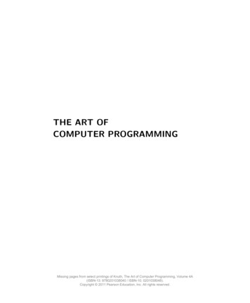
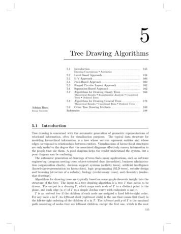
was a fascinating piece of technical brinkmanship: it was a completely mechanical computer, butinstead of using gears and wheels to represent the ten decimal digits (as Babbage had done in theprevious century, or IBM was doing with its Hollerith machines), Zuse decided to build a fully binarycomputer. His machine was based on components in which the forward linear movement of a smallrod or metallic plate represented a one, and no movement represented a zero (or vice versa,according to the component). Zuse developed novel types of mechanical logical gates and finishedthe first prototype of the machine in his parent’s living room. The sequence of events that led to theZ1 and subsequent machines has been appraised by Zuse himself in his autobiography [2].The Z1 was a mechanical but also a surprisingly modern computing machine: it was based on binarynumbers, it used a floating-point representation for the data and could perform the four basicarithmetic operations. The program was read from a punched tape (no conditional branch wasavailable though), and the results could be stored to or read from memory (16 words). The machinecycle was around 4 Hz.The Z1 was very similar to the Z3, finished in 1941, whose architecture has been already described inthe Annals [3]. However, the detailed high-level architecture of the Z1 has never been explainedbefore. The original prototype was destroyed during a bombing raid in 1943. Only a few sketches andphotographs of the mechanical components survived. In the 1980s, Konrad Zuse, who had retiredmany years earlier, obtained financing from Siemens and other German sponsors for building a fullreplica of the Z1 which is now housed in Berlin’s Technology Museum (Fig. 1). Zuse built the machinewith the help of two engineering students: He prepared a full set of blueprints, painstakingly drawingevery single mechanical component (to be cut from sheets of steel), and supervising the constructionover the course of several years at his own house in Hünfeld, Germany. The first sketches of the Z1reconstruction were drawn in 1984. In April of 1986 Zuse drew a timeline expecting to have themachine finished by December of 1987. When the machine was delivered to the Berlin museum in1989 it was shown running and computing some arithmetical operations on several occasions.However, the reconstructed Z1 was, like the original, never reliable enough to run unattended forlong stretches of time. It even failed at the inauguration and Zuse spent months repairing themachine. After Konrad Zuse passed away in 1995, the machine was never restarted again.Fig. 1: A view of the reconstructed Z1 in Berlin (from the Konrad Zuse Internet Archive [5]). The user can rotatethe view around the machine, can zoom in and out. The virtual display is based on thousands of linkedphotographs.2
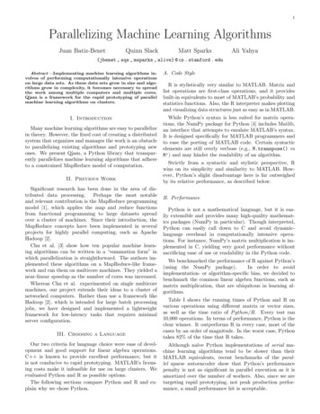
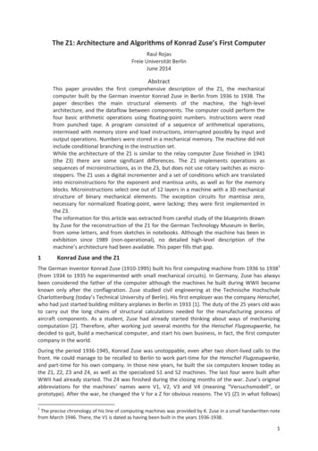
Although we have a reconstruction of the Z1 in Berlin, fate struck twice. Other than drawing theblueprints, Zuse made no serious effort to write a complete top-down description of thereconstructed Z1 (he expected a local university to do it). This would have been necessary, because itis evident from comparing the reconstruction with old photographs of the Z1 built in 1938, that thenew machine has been “streamlined”. The higher precision of the machining equipment available toZuse in the 1980s allowed him to build the machine using layers of steel plates which could be placedtighter together. The new Z1 fills a significantly smaller volume than the old Z1. It is also notcompletely clear if the new Z1 is strictly a one-to-one logical and mechanical clone of the originalmachine, or if Zuse’s experience with the Z3 and later machines allowed him to improve portions ofthe reconstructed Z1. In the set of mechanical blueprints drawn from 1984 to 1989, there are at leastsix different designs for the addition unit, having between five to eight, and finally up to 12mechanical layers.2 Zuse left no detailed written record which could allow us to answer suchquestions. Still worse, he rebuilt the Z1 and left no comprehensive logical description of it – for thesecond time! He acted like those celebrated clockmakers who only draw the parts of their watches,leaving no further explanation: first-rate clockmakers would need no further clarifications. His twostudent assistants documented only the memory and the tape reader, a heaven-sent piece ofinformation [4]. Visitors to the Berlin museum can only wonder at the thousands of componentsvisible in the machine. They can both wonder and despair, since it is almost impossible, even forprofessional computer scientists, to visualize the inner workings of this mechanical Leviathan. Themachine is there -- but unfortunately dead.Fig. 2: The mechanical layers of the Z1. The eight memory layers can be seen on the right, the 12 processorlayers on the left. The lower section with levers is used for transmitting the clock cycles to all parts of themachine.This paper is based on a careful study of the blueprints of the Z1, scattered notes in Zuse’snotebooks, and numerous on-site inspections of the machine. The reconstructed Z1 has been nonoperational for so many years because the steel plates used by Zuse bend under stress. For thispaper, more than 1100 large format drawings of the machine’s components were reviewed, as wellas 15.000 pages in notebooks (only a small fraction thereof contained information about the Z1though). I could only see a short video of parts of the machine operating (filmed almost 20 yearsago). Deutsches Museum in Munich houses 1079 blueprints from Zuse’s private papers, while theBerlin Technical Museum has another 314 in its archives. Fortunately, some blueprints include alsothe definition and timing of some microinstructions for the Z1, and also a few examples of bit by bithandwritten calculations made by Zuse. Such examples were probably used by Zuse to check themachine’s internal operation and find bugs. This information was like a Rosetta stone, which allowedus to correlate the Z1 microinstructions with the diagrams and blueprints, and also with our relatively2All the blueprints for the reconstruction of the Z1 have been made available through our „Konrad ZuseInternet Archive“ at http://zuse-z1.zib.de.3
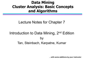
deep knowledge of the relay-computer Z3 (for which we have complete circuits [5]). The Z3 is basedon the same high-level architecture as the Z1, but is different in an important number of ways.This paper proceeds top-down: first we review the block architecture of the Z1, the layout of themechanical components, and I also provide some examples of the mechanical gates used by Zuse.We then look in more detail at the Z1 core elements: the clocked addition units for exponent andmantissa, the memory, and the microsequencer for arithmetical operations. We show the interplayof the mechanical elements and how the “sandwiched” layout of steel plates helped Zuse organizethe computation. We look at the multiplication and division process, at input and output. The lastpart of the paper briefly situates the Z1 in its historical context.2Block-architectureThe Z1 was a clocked machine. Being a mechanical device, the clock was subdivided into foursubcycles which consisted in the movement of mechanical components in four orthogonal directions,as shown in Fig. 2 (left side, see “cycling unit”). Each movement direction was called an“engagement” by Zuse. He aimed for a 4Hz clock cycle but the Berlin reconstruction never wasoperated faster than at 1Hz (four engagements per second). At that speed, a multiplication takesaround 20 seconds.Fig. 3: Block diagram of the Z1 (1936-38) according to the reconstruction of 1989. The original Z1 had only 16words of memory instead of 64. The punched tape was made of 35mm film tape. Each instruction was encodedusing 8 bits.The Z1 has a number of features later adopted in the Z3. From a modern perspective, the mostimportant innovations in the Z1 (see Fig. 3) were the following:4
a) It was based on a fully binary architecture for the memory and the processor.b) The memory was separated from the CPU. In the Berlin reconstruction, the memory andpunched tape reader constitute about one half of the machine. The processor, I/O consoles,and the microcontrol unit constitute the other half. The original Z1 had 16 words of memory,the reconstruction has 64.c) The machine was programmable: the program was read from punched tape using 8 bits (twobits for the opcode and six bits for memory addressing, or three bits for the opcode of thefour arithmetical and the two I/O operations). Therefore there were only eight instructions:the four basic arithmetical operations, load-from and store-to memory, one instruction forreading data from a decimal panel, and another for showing the contents of the resultregister on a mechanical decimal display.d) Floating-point was used for internal data representation, in the memory and in theprocessor. Therefore, the processor was divided into two parts: one for handling theexponents, another for handling the mantissas. The mantissa had 16 bits for the bits afterthe binary point. The bit to the left of the point was always 1 (normalized floating-point) anddid not have to be stored. Exponents were represented with 7 bits in two’s complementformat (running thus from -64 to 63). The sign of the floating-point numbers was stored inone additional bit. Therefore the word-length in memory was 24 bits (16 bits for themantissa, 7 for the exponent, one bit for the sign).e) The special case of zero in arguments or results (which cannot be expressed with anormalized mantissa, where the leading bit is always 1) can be handled within the floatingpoint representation as special values of the exponent. This was done in the Z3 but not in theZ1, also not in its reconstruction. Therefore, neither the original Z1, nor the reconstruction,can work with zero as intermediate result. Zuse was aware of this shortcoming, but he leftthe solution to the relay machine, which was easier to wire.f) The CPU was microcoded: operations were broken into sequences of microinstructions, onefor each machine cycle. The microinstructions produced a specific dataflow within thearithmetical-logical units (ALUs), which were running nonstop, adding whatever twonumbers were stored in its two input registers, in every cycle.g) Curiously, memory and processor ran independently: the memory would put data at orcollect data from the communication interface, whenever the punched tape gave the order.The processor would pick, or put data at the interface, when a load or store operation wasexecuted. It was possible to run only the processor and shut-down the memory, in whichcase the data at the interface, supposedly coming from the memory, became zero. It wasalso possible to run only the memory and shut-down the processor. This allowed Zuse todebug each half of the machine independently. When running together, a shaft connectingthe cycling units in each half synchronized both parts of the machine.Further innovations in the Z1 were similar to some of the ideas presented later in the Z3. Theinstruction set was practically the same as in the Z3 but the Z1 could not extract square roots. The Z1used discarded 35mm film tapes as punched tape.Fig. 3 shows the abstract diagram of the reconstructed Z1. Notice the two main halves of themachine: the memory is in the upper half, and the processor in the bottom half. Each half had itsown rotating cycling unit, which further divided each cycle into four mechanical movements in thedirections shown by the arrows. These four movements could be communicated to any part of themachine using the levers distributed under the computational components. The punched tape wasread, one instruction at a time. The instructions had different durations. Load and store operationstook one cycle, all other operations needed several cycles. The memory address was contained in thelower six bits of the 8 bit opcode, allowing the programmer to refer explicitly to 64 memoryaddresses.Memory and processor communicated through the buffer between both units shown in Fig. 1. In theCPU, the internal representation of the mantissa was extended to 20 bits: two additional bits were5
added before the binary point (for the binary powersand ), and two more bits for the lowestbinary powers (and), in order to increase the accuracy of the CPU for intermediate results.In the processor the mantissa had 20 bits representing the binary powersto.The decoder took an instruction from the punched tape reader, determined the operation, andstarted controlling the memory unit and the processor as needed. A number could be read frommemory to the first of two CPU floating-point registers (using a load operation). A further loadoperation would read a number from memory to the second CPU register. The two registers could beadded, subtracted, multiplied, or divided in the processor. Such operations require exponentaddition or subtraction (with a two’s complement adder), as well as an adder for the mantissas. Thesign of the result of a multiplication or division was handled in a “sign unit” connected directly to thedecoder.An input instruction from the punched tape stopped the machine and allowed the operator to enterdata by pulling four decimal digits from a mechanical panel, entering the exponent of the floatingpoint representation with a small lever, and also the sign of the number. The operator could thenrestart the machine. An output instruction stopped also the machine and showed the contents of theresult register in a decimal mechanical panel, until the operator restarted the machine pressing alever.The microsequencer in Fig. 3 constitutes, together with the exponent and mantissa addition units,the core of the computation capabilities of the Z1. Each arithmetical or I/O operation was dividedinto “phases”. The microsequencer started counting and selected the appropriate microoperation inthe corresponding layer, out of 12 possible layers of mechanical components in the addition units.Therefore, a minimal program in a punched tape could be, for example: 1) Load number fromaddress 1 (implicitly to the first CPU register), 2) Load number form address 2 (implicitly to thesecond CPU register), 3) add, 4) show result in decimal. This program could thus allow the operatorto use the Z1 as a simple mechanical calculator for predefined operations. Of course, the sequence ofcomputations could be much longer: automatic sequences of operations were programmed using thememory as storage for constants and intermediate results (in the latter Z4 computer, one tape usedfor mathematical computations was two meters long).The architecture of the Z1 can be summarized using modern terminology as follows: it was aprogrammable normalized floating-point Von Neumann machine (processor and memory wereseparate), with external read-only program, with a memory for sixteen 24-bit words. It was capableof accepting decimal numbers of four digits (and an exponent, as well as a sign) as input, fortransforming them into binary. It was capable of performing the four arithmetical operations withthe data. The binary floating-point result could be transformed back into decimal scientific notationreadable by the user. There was no conditional, nor unconditional branching in the instruction set.Exception handling for zero results was lacking. Each instruction was broken into microinstructions“hardwired” in the machine. A microsequencer orchestrated the execution of the microinstructions.In the single surviving video of the machine operating, it looks to the eye as the moving parts of aheirloom. But this machine was weaving numbers.3Layout of the mechanical componentsThe Berlin reconstruction of the Z1 is based on a very clean layout. All mechanical components seemto have been arranged in an optimal way. We mentioned that Zuse designed at least six differentversions of the processor. The relative position of the main components was fixed from thebeginning and might reflect the original distribution of the mechanical elements in the original Z1.There are two main divisions: a gap separates the memory from the processor (as shown in Fig. 3). Infact, both parts of the machine could be actually pulled apart for debugging purposes since theywere mounted on separate tables with rollers. A further horizontal plane subdivides the machine6
into an upper part containing the computational components (those visible in photographs of theZ1), and a lower part containing all the synchronization levers. This Z1 “underworld” is only visiblewhen the visitor bends over to look underneath the computational skyline. Fig. 4 is a drawing fromthe blueprints showing the computation and the synchronization levels for part of the processor.Notice the 12 layers of computational components and the lower section with three levels for levers.This blueprint is a good example of how difficult it can be to interpret the drawings. While there ismuch detail about the size of the parts, there are just a few annotations about their use.Fig. 4: Blueprint for the computation and synchronization layers of the Z1 (exponents unit)Fig. 5 shows the distribution of logical components in the reconstructed Z1, seen from above, and asdrawn by Zuse, further annotated with the logical functionality of each block (this sketch has beenavailable since the 1990s). On the upper part we see the three memory banks. Each can contain eight8-bit words per layer. Every memory bank has 8 mechanical layers, so that a total of 64 words can bestored. The first memory bank (10a) is used for the exponent and sign, the last two banks (10b, 10c)are used for the lower 16 bits of the mantissa of the stored numbers. This distribution of bits allowedZuse to build three identical 8-bit memory banks and use them for exponent and mantissa,simplifying thus the mechanical construction.Between memory and processor there is a “buffer” for passing numbers to the processor (blocks12abc), or for receiving numbers from it. There is no way of coding constants in the punched tape. Allnumbers have to be entered by the user using the decimal input panel (block 18, right side), or mustbe generated by the computer itself as intermediate results.Each unit in this diagram shows just the uppermost layer. Remember that the Z1 is built like a“sandwich” of mechanical parts. Each computational layer is strictly separated from the laver aboveor below (each layer has a metallic floor and a metallic ceiling). Communication between layers isdone using vertical rods than can pass movement from one layer to those above or below it. Thevertical rods are the small circles drawn between the rectangles representing layers of computation.The somewhat larger circles drawn inside the rectangles represent logical operations. Inside eachcircle we can find a binary gate (and going down through the layers, up to 12 gates for each circle).This drawing allows us to make an estimation of the number of logical gates present in the Z1. Not allunits have the same height, and not all layers are populated with mechanical components. Aconservative estimation of the number of binary elements would be 6.000 gates.7
Fig. 5: Diagram of the Z1, showing the mechanical building blocks.Zuse assigned the numbers shown in Fig. 5 to the different modules of the machine. The purpose ofthe modules is the following:Memory Block11a:Decoder for the six-bit memory addresses11b:Punched tape reader and op-code decoder10a:Memory bank for 7-bit exponents and sign10b, 10c: Memory banks for the fractional part of the mantissa12abc:Interface to and from the processor for load or store operationsProcessor Block16:Control and sign unit13:Multiplexer for the two ALU registers in the exponent part14ab:Multiplexer for ALU registers, one-bit two-way shifters for multiplication and division15a:ALU for the exponent15bc:20-bit ALU for the normalized mantissa (18 bits for the fractional part)17:Microcode control18:Decimal input panel to the right, output panel to the leftOne can imagine computation flowing in this diagram from top to bottom: from the memory, thedata comes to fill the two registers available to the programmer (which we call F and G). These tworegisters are distributed along blocks 13 and 14ab. The two registers are fed to the ALUs (blocks15abc). The result is cycled back to register F or G (as result register), or back to memory. The resultcan be shown in the decimal display using the “re-translate” instruction (binary to decimalconversion).In what follows we look in more detail to each module, concentrating our efforts in the maincomputational components.8
4The mechanical gatesThe mechanical structure of the Z1 can be best understood by looking at a few simple examples ofthe type of binary logic gates that Zuse used in his machines. The classical digital representation fordecimal digits has always been the rotary dial. A gear is divided into ten sectors -- by rotating thegear it is then possible to count from zero to nine. Zuse decided as early as 1934 to use the binarysystem (which he called, following Leibniz, the dyadic system). In Zuse’s technique, a planar plate canhave one of two positions (0 or 1). It is possible to move from one state to the other using linearmotion. Logical gates pass movement from one plate to another, according to the value of therepresented bits. The structures are three-dimensional: they consist of arrangements of superposedplanar plates which transmit movement usually through cylindrical rods or pins positioned vertically,at right angles to the plates.We show examples of the three basic gates: conjunction, disjunction, and negation. There are manypossible mechanical realizations for the main idea, and Zuse showed great creativity drawing alwaysthe variation of a gate that best fitted the 3D structure of the machine. Fig. 5 shows what Zuse calledthe “elementary gate”. The “actor plate” can be regarded as the machine cycle. This plate movescyclically from right to left and back. The upper plate is the data bit we are using for control. It can bein the position 1 or 0. The rod going though the openings moves horizontally following the plate(keeping its verticality). If the upper plate is in the 0-position, the actor plate’s movement cannot betransmitted to the actuated plate (see Fig. 6, left side). If the data bit plate moves to the 1-position,the movement of the actor plate is transmitted to the actuated plate. This is what Konrad Zuse calleda “mechanical relay”, just a switch that closes a mechanical “current”. This elementary gate can thuscopy a bit from the upper to the acted plate, rotating the movement of the bit by 90 degrees.Figure 6: An elementary gate is a switch. If the data bit is 1, the actor and actuated plates are connected. If thedata bit is zero, they are disconnected and the movement of the actor is not transmitted.Fig. 7 shows now such plate arrangements as seen from the top. The actor plate is shown with itsopening. The control plate in green pulls the circle (rod) up or down. The actuated plate (red) canmove to the right or left, but only when the rod is in such a position that the actor’s opening movesthe rod. There is a drawing of the equivalent switch to the left of each mechanical top view. Thecontrol bit can close or open the gate. The actor plate can be pulled or pushed (as shown by thearrows). Zuse’s convention was to always draw the switch in the zero position of the control bit, asdone in Fig. 7. Zuse preferred plates to be pushed by the actor plate (right side of Fig. 7) rather thanbe pulled (left side of Fig. 7). It is now very easy to build a negation gate, by using a closed switchwhich is opened by the position 1 of the control bit (as shown in the bottom two diagrams in Fig. 7).9
Having a mechanical relay, it is now straightforward to build the rest of the logical operations. Fig. 8shows the necessary circuits, now only using abstract notation. The equivalent mechanicalcontraptions are easy to conceive.Fig. 7: Some variations of the elementary gate and Zuse’s abstract notation for mechanical relays. The relaysare drawn as switches. By convention, the drawing always shows the zero-position of the control bit. Thearrows show the possible movements. The actuator plate can be pulled to the left (left side diagrams), orpushed to the right (right side diagrams). The initial position of the mechanical relay can be in the closedposition (lower two diagrams). In that case the relay acts as a negation, since the output is the negation of thecontrol bit.Fig. 8: Some logical gates built from mechanical relays. The lowest diagram, an XOR, can be built by usingmechanical relays with two possible actuated plates, as shown in the diagrams. The mechanical equivalents areeasy to design.10
Now everybody can start to build his/her Zuse mechanical computer. The basic element is themechanical relay. More complex connections (like the relays with two actuated plates) can bedesigned, and the corresponding mechanics has to be built using plates and rods.The main problem for building a complete computer is to interconnect all components. Notice thatthe control bit always moves orthogonally to the result bit. Each completed logical operation rotatesthe mechanical movement by 90 degrees. The next logical operation rotates the movement by 90degrees, and so on. After four gates, we are back to the original direction of movement. This is whyZuse’s cycling units used the four directions NESW. Within a machine cycle it is possible to executefour layers of logical computations. The logical gates can be simple, such as a negation, or complex,such as a gate with two actuated plates (half of an XOR). The clocking in the Z1 is such that themachine completes an addition in four engagements: in engagement IV the arguments are loaded.Engagements I and II compute partial sums and carries, and engagement III the final result.Result bits can be transferred to different horizontal levels than the level at which the input bitsmove. That is, rods can be also used to move bits “up” or “down” between the layers of the machine
The information for this article was extracted from careful study of the blueprints drawn by Zuse for the reconstruction of the Z1 for the German Technology Museum in Berlin, from some letters, and from sketches in notebooks. . or IBM was doing with its Hollerith machines), Zuse decided to build a fully binary