Transcription
280-0065-00-AOCyan 280-0065-00 Compatible TAA Compliant 1000Base-DWDM SFP Transceiver (SMF, 1547.72nm, 120km, LC,DOM)Features INF-8074 and SFF-8472 Compliance Duplex LC Connector Commercial Temperature 0 to 70 Celsius Single-mode Fiber Hot Pluggable Excellent ESD Protection Metal with Lower EMI RoHS Compliant and Lead FreeApplications 1x Fibre Channel Gigabit Ethernet over DWDM Access, Metro and EnterpriseProduct DescriptionThis Cyan 280-0065-00 compatible SFP transceiver provides 1000Base-DWDM throughput up to 120km oversingle-mode fiber (SMF) using a wavelength of 1547.72nm via an LC connector. It is guaranteed to be 100%compatible with the equivalent Cyan transceiver. This easy to install, hot swappable transceiver has beenprogrammed, uniquely serialized and data-traffic and application tested to ensure that it will initialize andperform identically. Digital optical monitoring (DOM) support is also present to allow access to real-timeoperating parameters. This transceiver is Trade Agreements Act (TAA) compliant. We stand behind the qualityof our products and proudly offer a limited lifetime warranty.AddOn’s transceivers are RoHS compliant and lead-free.TAA refers to the Trade Agreements Act (19 U.S.C. & 2501-2581), which is intended tofoster fair and open international trade. TAA requires that the U.S. Government mayacquire only “U.S. – made or designated country end products.”Rev. 091421
Regulatory Compliance ESD to the Electrical PINs: compatible with MIL-STD-883E Method 3015.4 ESD to the LC Receptacle: compatible with IEC 61000-4-3 EMI/EMC compatible with FCC Part 15 Subpart B Rules, EN55022:2010 Laser Eye Safety compatible with FDA 21CFR, EN60950-1& EN (IEC) 60825-1,2 RoHS compliant with EU RoHS 2.0 directive 2015/863/EUWavelength Guide (100GHz ITU-T Channel)ITU Channel #Frequency (THZ)Center Wavelength 51556.55
61.421562.231563.051563.86Absolute Maximum RatingsParameterSymbolMin.Max.UnitMaximum Supply VoltageVcc-0.54.0VStorage TemperatureTS-4085 COperating Case TemperatureTc070 COperating HumidityRH585%Electrical Characteristics (TOP 25 C, Vcc 3.3Volts)ParameterSymbolMin.Typ.Max.UnitPower Supply VoltageVcc3.143.303.46VPower Supply CurrentIcc450mASupply VoltageVMAX-0.54WDifferential data input swingVin,pp2501200mVInput differential impedanceZinTransmitter100ΩReceiverDifferential data output swingVout, ppData output rise/fall timeTr/Tr2501008.0mV175psNotes
Optical sTransmitterWavelength Spacing100Optical WavelengthTλx-0.1Optical Power (average)PAVE0Transmitter and Dispersion PenaltyTDPOptical Extinction RatioERSpectral Width λSidemode Suppression RatioSMSROptical Rise/Fall Time (20%-80%)tr/tfxGHzX 0.1nm5dBm3dB8.2dB0.330nmdB260Eye Diagram1psCompatible with IEEE 802.3ReceiverReceiver WavelengthλCReceiver Sensitivity (average)RAVEReceiver overloadPmaxLOS AssertLOSALOS De-AssertLOSDLOS dBmdBmNotes:1. Coupled into a Single-mode fibre2. Average power, back-to-back, @1.25Gbps, BER 1E-12, PRBS 231-1.3. Exceeding the Receiver overload can physically damage the module. Please use appropriateattenuation.
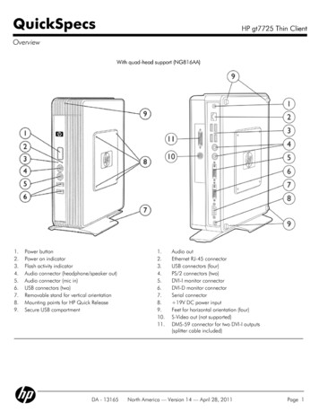
Pin nsmitter Ground (Common with Receiver Ground).12TX FaultTransmitter Fault. LVTTL-O23TX DisableTransmitter Disable. Laser output disabled on high or open. LVTT-I.34SDA2-Wire Serial Interface Data Line (Same as MOD-DEF2 in INF-8074i). LVTTL-I/O.5SCL2-Wire Serial Interface Data Line (Same as MOD-DEF2 in INF-8074i). LVTTL-I.6MOD ABSModule Absent, Connect to VeeT or VeeR in Module.47RS0Rate Select 0. Not used58LOSLoss of Signal indication. Logic 0 indicates normal operation. LVTTL-O.29RS1Rate Select 1. Not used510VeeRReceiver Ground (Common with Transmitter Ground).111VeeRReceiver Ground (Common with Transmitter Ground).112RD-Receiver Inverted DATA out. AC Coupled. CML-O.13RD Receiver Non-inverted DATA out. AC Coupled. CML-O.14VeeRReceiver Ground (Common with Transmitter Ground).15VccRReceiver Power Supply.16VccTTransmitter Power Supply.17VeeTTransmitter Ground (Common with Receiver Ground).18TD Transmitter Non-Inverted DATA in. AC Coupled. CML-I.19TD-Transmitter Inverted DATA in. AC Coupled. CML-O.20VeeTTransmitter Ground (Common with Receiver Ground).111Notes:1. The module signal ground contacts, VeeR and VeeT, should be isolated from the module case.2. This contact is an open collector/drain output and should be pulled up to the Vcc Host with resister inthe range 4.7KΩ to 10KΩ. Pull ups can be connected to one or several power supplies, however the hostboard design shall ensure that no module contract has voltage exceeding module VccT/R 0.5.V.3. Tx Disable is an input contact with a 4.7KΩ to 10KΩ pull-up resistor to VccT inside module.4. Mod ABS is connected to VeeT or VeeR in the SFP module. The host may pull the contract up toVcc Host with a resistor in the range from 4.7KΩ to 10KΩ. Mod ABS is asserted “High” when the SFP module is physically absent from a host slot.5. Internally pulled down per SFF-8431
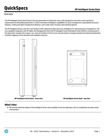
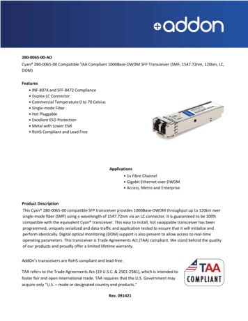
Pin-out of connector Block on Host boardRecommended Circuit Schematic
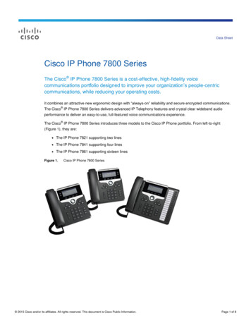
Mechanical SpecificationsSmall Form Factor Pluggable (SFP) transceivers are compatible with the dimensions defined by the SFP MultiSourcing Agreement (MSA).EEPROM InformationEEPROM memory map specific data field description is as below:
About AddOn NetworksIn 1999, AddOn Networks entered the market with a single product. Our founders fulfilled a severe shortagefor compatible, cost-effective optical transceivers that compete at the same performance levels as leadingOEM manufacturers. Adhering to the idea of redefining service and product quality not previously had in thefiber optic networking industry, AddOn invested resources in solution design, production, fulfillment, andglobal support.Combining one of the most extensive and stringent testing processes in the industry, an exceptional freetech support center, and a consistent roll-out of innovative technologies, AddOn has continually set industrystandards of quality and reliability throughout its history.Reliability is the cornerstone of any optical fiber network and is in engrained in AddOn's DNA. It has played akey role in nurturing the long-term relationships developed over the years with customers. AddOn remainscommitted to exceeding industry standards with certifications from ranging from NEBS Level 3 to ISO9001:2005 with every new development while maintaining the signature reliability of its products.U.S. HeadquartersEmail: sales@addonnetworks.comTelephone: 1 877.292.1701Fax: 949.266.9273Europe HeadquartersEmail: salessupportemea@addonnetworks.comTelephone: 44 1285 842070
Pin Descriptions Pin Symbol Name/Descriptions Ref. 1 VeeT Transmitter Ground (Common with Receiver Ground). 1 2 TX Fault Transmitter Fault. LVTTL-O 2 3 TX Disable Transmitter Disable. Laser output disabled on high or open. LVTT-I. 3 4 SDA 2-Wire Serial Interface Data Line (Same as MOD-DEF2 in INF-8074i). LVTTL-I/O. 5 SCL 2-Wire Serial Interface Data Line (Same as MOD-DEF2 in INF-8074i).