Transcription
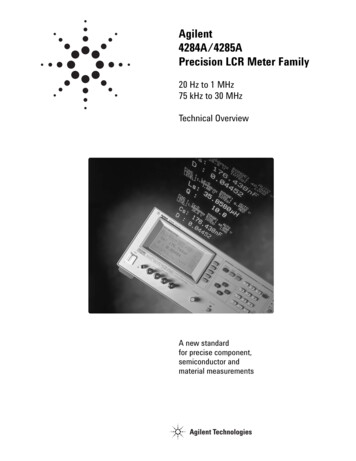
Agilent4284A/4285APrecision LCR Meter Family20 Hz to 1 MHz75 kHz to 30 MHzTechnical OverviewA new standardfor precise component,semiconductor andmaterial measurements
Agilentprecision LCR meter familyUtilize state-of-the artmeasurement technologies 6-digits of resolution at any range Basic accuracies of0.05% (Agilent 4284A) and0.1% (Agilent 4285A) 20 impedance parameters to accessand measureKey specifications Constant V or I test signal level 20 Vrms test signal level(Agilent 4284A)Agilent 4284A precision LCR meterTest frequencyMeasurement20 Hz to 1 MHz over 8610 selectable frequenciesrange1Move your process towarderror-free operation Z , R, X :0.01 mΩ to 99.9999 MΩ Y , G,B :0.01 nS to 99.9999 SC :0.01 fF to 9.99999 FL :0.01 nH to 99.9999 kHD :0.000001 to 9.99999Q :0.01 to 99999.9 Instrument setup state storage Comparator functions Selectable frequency errorcorrections Open, short and load correctionsremove parasiticsBasic accuracy Z , C and L:0.05% D:0.0005Test signal level rangeVoltageCurrent5 mVrms to 2 Vrms50 µArms to 20 mArmsConstant test signal level rangeVoltage10 mVrms to 1 VrmsCurrent100 µArms to 10 mArmsMeasurement time 239 ms/190 ms/830 ms at 1 kHz4284A with Option 4284A-001Test signal level rangeVoltageCurrent5 mVrms to 20 Vrms50 µArms to 200 mArmsConstant test signal level rangeVoltage10 mVrms to 10 VrmsCurrent100 µArms to 100 mArmsInternal DC bias1. Refer to specifications for complete accuracy.2. Supplimental information only.4284A with Option 4284A-002 and 42841ADC current bias2 (1 mV 40 V), 100 mA, 0.1% accuracy0.01 A to 20 A (with 42841A and 42842A)0.02 A to 40 A (with 42841A x 2 ea., 42842B and 42843A)
Satisfying yourperformance needsKey specificationsAgilent 4285A precision LCR meterTest frequency75 kHz to 30 MHz with 100 Hz resolutionMeasurement range1 Z , R, X :0.01 m Ω to 99.9999 MΩ Y , G,B :0.01 nS to 99.9999 SC :0.01 fF to 999.999 µFL :0.001 nH to 99.9999 HD :0.000001 to 9.99999Q :0.01 to 99999.9Adapt instrument configurationsto fit your test needs Internal voltage biasing up to 40 Vdc3 High current biasing up to 40 A dc3(Agilent 4284A)Basic accuracy Z , C and L:0.1% D:0.001 Wide range of frequencies, 20 Hz to30 MHzTest signal level rangeVoltageCurrent5 mVrms to 2 Vrms200 µArms to 20 mArms BIN’ing and comparator functions forhandlers SMD, axial and radial test fixtures3Constant test signal level rangeVoltage10 mVrms to 1 VrmsCurrent100 µArms to 20 mArmsMeasurement time230 ms/65 ms/200 msSimplify your systemdevelopment and integration Programming language compatiblewith IEEE 488.2 Test port extensions: maximum 4 mfor 4284A3 and 2 m for 4285A Identical operation for the entirefamily of products Scanner, handler and GPIB interfaces34285A with Option 4285A-001Internal DC bias (1 mV 40 V), 100 mA, 0.1% accuracy4285A with Option 4285A-002, 42841A, and 42842CDC current bias0.01 A to 10 A1. Refer to specifications for complete accuracy.2. Supplimental information only.3. The options, the accessories, or the test fixturesare needed.3
Versatile componentmeasurementsCharacterize inductive devices Sweep high current conditions Identify device properties precisely Test to RF frequenciesLow frequency measurements:Agilent 4284AInductance rolloff dueto high dc current biasInductive devices can now be accuratelycharacterized from 20 Hz to 1 MHz with adc bias current up to 40 A1 dc.High frequency measurements:Agilent 4285AThe Agilent 4285A’s wide 75 kHz to 30 MHzrange allow you to test RF inductors withimproved accuracy and 0.001 nH resolution.Magnetic heads, ferrite-cores, and powerinductors that need to be tested at aspecified current signal level can be easilytested with the Agilent 4285A.Precise ceramiccapacitor measurements Test at 1 kHz and 1 MHz Resolve measurements to low values Maintain constant signal levels1 kHz and 1 MHz are the primary testingfrequencies for ceramic materials andcapacitors. The Agilent 4284A can providethese test frequencies while maintainingan equally excellent accuracy and 6-digitsof measurement resolution.1 MHz accuracies of capacitance (0.05%)and dissipation factor (0.0005) are essentialfor characterizing DUTs with low dissipationfactors. Dissipation factors can change asa function of the applied test signal levelto the DUT. For reliable and consistentmeasurements, the Agilent 4284A canmaintain a constant voltage test signallevel.1. Need Option 4284A-0014Dissipation factor risedue to high ac signal
Adaptableparameter testingDiscover new material properties High accuracy and precisemeasurements Wide frequency ranges High test signal levels Agilent 16451B dielectric test fixtureA material’scharacteristics versusfrequencyThe Agilent precision LCR meter familyprovides the accuracy, resolution, hightest signal and bias levels1 required formaterial measurements. Using theAgilent 16451B dielectric test fixtureprovides you with accurate permittivityand dissipation factor measurements.The ability to output a constant test signallevel permits repeatable and accuratemagnetic/dielectric measurements. Boththe Agilent 4284A and Agilent 4285A offervariable voltage and current test signallevel control.Semiconductor testing Extend the test cable to the DUTDetect small parameter changesRapidly acquire dataTest at multiple frequenciesBoth instruments allow you to extend thefront panel measurement port through testcables, switches, and probers directly tothe DUT. The 6-digits of resolution giveyou the ability to sense and identifychanges not normally seen by conventionalLCR meters.C-V characteristicssample—MOS diodeThe accuracies of the Agilent 4284A atkey test frequencies up to 1 MHz permitcomplete DUT evaluation for eitherproduction or laboratory needs.For high speed device testing at frequencies above 1 MHz, the best solution is theAgilent 4285A.1. Need Option 4284A/4285A-0015
One LCR meter familyfor your product’s life cycleResearch and developmentProduction testResearch tomorrow’s electronic components nowReduce production test factors Increase measurement confidenceThe basic accuracies are:Agilent 4284A 0.05% and Agilent 4285A 0.1%. Detect 1 ppm changesThe 6-digits of resolution permit you to measure differencesin materials not detectable before. Fit the instrument to your test needsFor low frequency applications the Agilent 4284A is the idealtool. For testing at RF frequencies the Agilent 4285A is thebest solution.Material designQuality assuranceDesign and test new materialsAutomated quality assurance Material test fixturesFor accurate permittivity and dissipation factor measurementsof solid dielectric materials, the 16451B dielectric test fixtureis provided. The 16452A liquid test fixture is provided for thepermittivity measurements of liquids with minimal conductivity. Sample programBy using the sample program in the operation manual of16451B, complex permittivity can be calculated rather easilyand instantly. In addition, with the use of a spreadsheet software, the frequency response of permittivity can be displayedin a graph.1. For 4284A, need Option 4284A-0062. Choose the combination from Option 4284A/4285A-201, 4284A/4285A-202, or4284A/4285A-3013. Need Option 4284A/4285A-3016 Increase test throughputThe precision LCR meter family reduces testing costsby providing accurate high throughput testing. Interface easily to handlersBuilt-in comparator, cable compensation1, and interfaces2permit system integration. Minimize operator errorInstrument state storage minimizes costly setup errors. Reduce your system development timeThe Agilent 4284A and Agilent 4285A are designed to be usedas elements in systems. This means GPIB, programming,and the ability to interface with scanners3. Painlessly integrate the systemGPIB and a scanner3 interface allow the instruments to easilyintegrate into system configurations. Leverage your programming experienceLearning to program one instrument automatically meansyou learn both.
Comprehensive incoming inspectionSatisfying difficulties and requirementsof impedance measurements duringincoming inspectionMany types of measurements requiring a variety of measurementconditions have to be carried out during incoming inspection.However, as measurement instruments cannot perform all of themeasurements required, substitute measurements are made. Onthe other hand, purchasing all the necessary equipment wouldsubstantially increase capital costs.By employing the precision LCR meter family, a wide frequencyrange is covered (20 Hz to 1 MHz for 4284A and 75 kHz to30 MHz for 4285A) and various test signal levels can be set(20 Vrms/200 mArms for 4284A Option 4284A-001 and2 Vrms/20 mArms for 4285A). In addition, the ALC functionallows measurements of constant-voltage and constant-currentsignals, and the added capability of Option 4284A/4285A-001enables up to 40 V of dc bias to be applied to the DUT. As aresult of these features, a variety of measurement conditions canbe carried out.Built-in functionalitiesfor efficient measurementsIn order to save time and facilitate the efficiency of measurementroutines, the precision LCR meter family has the following features.The memory card1 allows the measurement conditions to be preset for various components with different measurement needs.The comparator function can be set to sort into a maximum of 10BINs, enabling many components to be handled during inspection.The Option 4284A/4285A-301 scanner interface solves the problem of having discrepancies in measurement values for differentchannels of the switching matrix by allowing channel compensation for up to 128 channels.Furthermore, the precision LCR meter family achieves high accuracymeasurements (basic Z measurement accuracy: 0.05% for4284A and 0.1% for 4285A), permitting the characteristics ofinductors and capacitors to be evaluated with excellent reliability.Also, built-in compensation functions reduce the influence of testfixtures to a minimum, further raising the reliability.1. Need Option 4284A/4285A-0047
User friendly InterfaceSimple front panel operation Clearly view the display See all instrument settings Interactive softkeys for simple controlDirectly view all instrument settings andmeasurement results on the large LCDdisplay. This simplifies operation andimproves operator efficiency by minimizingreadout error.The softkeys simplify front panel operationby allowing the user to easily changeinstrument states by moving the LCDcursor with cursor keys. The softkeyswill automatically change to reflect thecursor’s position. This minimizes thenumber of menus and key strokes.Customized test frequenciesNon-volatile memory Eliminate costly setup errors Increase user productivity Archive testsThe instruments contain two types of useraccessible memory; internal and external(memory cards)1. The memory can easilybe used to store measurement setups.Later, a setup can be loaded back into theinstrument. This reduces test setup errorsand increases the user’s productivity.The memory can store 10 different instrument states, complete with correctiondata and system configuration. Entiresetups including limit information cannow be stored and loaded using eitherthe internal memory or the memory card1.The memory card1 system is completelyelectronic and is based on EEPROM.1. Need Option 4284A/4285A-0048Inserting the memory card1
Testing with theproper toolsMeasure the components’performance in yourpower supply Test your components under loadconditions Bias inductive devices with highcurrents Satisfy your needs with the rightinstrumentDesigning advanced switching powersupplies require the use of inductors andtransformers that operate in the RFregions.For low frequencies, the Agilent 4284A1precision LCR meter with theAgilent 42841A bias current source,and the 42842A/B bias current testfixtures all combine to form a 40 A dctest system.High current bias for inductor testing under load conditionsWhere a high frequency measurementis required, use an Agilent 4285A2, anAgilent 42842C bias current test fixture,and an Agilent 42841A bias current sourceto achieve up to 10 A dc biasing withmeasurements at 30 MHz.Reduce systemdevelopment timeThe 4284A and 4285A employ a programming language, which is compatible withthe IEEE 488.2. Since the command namesare similar to the measurement functions,the time spent for creating and debuggingprograms can be largely minimized. Theoperation manual lists several key sampleprograms, allowing the user to efficientlycreate a program for their measurementsystem.Code generation made easy1. Need Option 4284A-0022. Need Option 4285A-0029
SpecificationsMeasurement functionsAll specifications are commonto the Agilent 4284A and Agilent 4285Aunless otherwise noted.Measurement parameters Z (impedance), Y (admittance), q (phase), R (resistance), X (reactance),G (conductance), B (susceptance), L (inductance), C (capacitance), Q (quality factor),D (dissipation factor), ESR (equivalent series resistance) and Rp (parallel resistance).20 parameter combinations are availableEquivalent circuit modes:Series and parallelMathematical functions:Deviation and percent deviationTrigger:Internal, external and manualDelay time:0 to 60.000 s in 1 ms stepsMeasurement terminals:Four-Terminal PairTest cable lengths:Agilent 4284A-standard:Option 4284A-006:Agilent 4285A-standard:0 and 1 meteradds 2 and 4 meter extension0.1 and 2 metersIntegration time:Short, medium and longTest signalTest frequency:Agilent 4284A:Agilent 4285A:20 Hz to 1 MHz, 8610 selectable frequencies75 kHz to 30 MHz, 100 Hz stepsFrequency accuracy: 0.01%Output impedance:Agilent 4284A: standard:Option 4284A-001:Agilent 4285A:AC test signal modes:Normal:Constant:100 Ω 3%100 Ω 6%(25 0.5 fm) Ω 10% @ 1 MHz, 30% @ 30 MHz,fm test frequency in MHzPrograms selected voltage or current at the measurementterminals when they are opened or shorted, respectively.Maintains selected voltage or current at the deviceunder test independent of changes in the device’simpedance.AC test signalAgilent 4284A: standardNormalConstantVIVIRange5 m Vrms to 2 Vrms50 µArms to 20 mArms10 m Vrms to 1 Vrms100 µArms to 10 mArmsAgilent 4284A with Option 4284A-001RangeNormalV5 m Vrms to 20 VrmsI50 µArms to 200 mArmsConstantV10 m Vrms to 10 VrmsI100 µArms to 100 mArmsAccuracy (10% 1 mVrms) (10% 10 µArms) (6% 1 mVrms) (6% 10 µArms)Accuracy (10% 1 mVrms) (10% 10 µArms) (10% 1 mVrms) (10% 10 µArms)Specifications continued on page 1110
SpecificationsAgilent 4285A: standardContinued from page 10NormalConstantVIVIRange5 m Vrms to 2 Vrms200 µArms to 20 mArms10 m Vrms to 1 Vrms100 µArms to 20 mArmsAccuracy (8% 0.4 fm% 1 mVrms) (8% 1 fm% 40 µArms) (6% 0.2 fm% 1 mVrms) (6% 0.2 fm% 40 µArms)fm: test frequency in MHzDC bias:Standard:0 V, 1.5 V and 2 V (Agilent 4284A only)WithOption 4284A/4285A-001: 0 V to 40 V Rear panel DC bias monitor, BNC connectorRange (0.000 to 4.000) V (4.002 to 8.000) V (8.005 to 20.000) V (20.01 to 40.00) VResolution1 mV2 mV5 mV10 mVAccuracy (0.1% to 1 mV)1 (0.1% to 2 mV)1 (0.1% to 5 mV)1 (0.1% to 10 mV)1Measurement rangeParameter Z , R, X: Y , G, B:C:L:D:Q:q: %Range0.01 mΩ to 99.9999 MΩ0.01 nS to 99.9999 S4284A: 0.01 fF to 9.99999 F4285A: 0.01 fF to 999.999 µF4284A: 0.01 nH to 99.9999 kH4285A: 0.001 nH to 99.9999 H0.000001 to 9.999990.01 to 99999.9-180.000 to 180.000 -999.999% to 999.999%DisplayLCD Dot-matrix type display. Capable of displaying: measured values, controlsettings, comparator limits and decisions, list sweep tables, self test messagesand annunciations.Correction functionOpen/short:Eliminates measurement errors due to stray parasiticimpedance in the test fixture.Load:Improves measurement accuracy by using a calibrateddevice as a reference.List sweep functionA maximum of ten frequencies or test levels can be programmed. Single orsequential testing can be performed. When Option 4284A/4285A-001 is installed,dc bias sweep can also be performed.1. Refer to measurement accuracy.Specifications continued on page 1211
SpecificationsContinued from page 11Comparator functionTen bin sorting for the primary measurement parameter, IN/OUT for the secondarymeasurement parameter.Bin count:0 to 999999List sweep comparator:HIGH/IN/LOW decision output for each point in the listsweep table.Other functionsStore/load:Ten instrument setups can be stored/loaded from theinternal non-volatile memory. Ten additional setups canalso be stored/loaded from each memory card1.GPIB:All instrument control settings, measured values,comparator limits, list sweep tables, and self test results.Memory:Memory buffer can store a maximum of 128 measurementresults and output the date over GPIB, ASCII and 64 bitbinary data formats.OptionsOption 4284A/4285A-001:Power amplifier/dc biasThis option cannot be operated simultaneously withOption 4284A/4285A-002.Agilent 4284A:Increases the AC test signal to 20 Vrms/0.2 Arms.Extends bias range to variable 40 Vdc. Rear panel BNCfor dc voltage monitor.Agilent 4285A:Adds variable 40 Vdc. Rear panel BNC for dc voltagemonitor and current monitor.Option 4284A/4285A-002:Accessory control interface/bias currentInterface allows the Agilent precision LCR meter tocontrol the Agilent 42841A bias current source.This option cannot be operated simultaneously withOption 4284A/4285A-001.Option 4284A-006:2 m/4 m cable length operation (4284A only)Increases test cable length capability. Adds 2 and 4meter operation.Option 4284A/4285A-201:Handler interfaceThis is a general purpose comparator/handler interface.Nine-sets of HIGH/LOW limits can be input allowing10-bin sorting for L, C, or IZI. The handler interfaceenables systemization with an automatic componentsorting machine. All signals are optically isolated.Option 4284A/4285A-202:Handler interfaceOption 4284A/4285A-301:Scanner interfaceOpen/short/load correction data for multiple channelsis stored in non-volatile memory, a maximum of 128 forthe Agilent 4284A and 90 for the Agilent 4285A. Threefrequencies can be corrected on the Agilent 4284Awhile seven frequencies can be corrected on theAgilent 4285A.1. Need Option 4284A/4285A-004Specifications continued on page 1312
SpecificationsGeneralContinued from page 12Power requirements100 V/120 V/220 V 10%, 240 V 5%/-10%,47 Hz to 66 Hz.Power consumption200 VAOperating temperatureand humidity0 C to 55 C, 95% RH at 40 CSize426(W) x 177(H) x 498(D) mmWeightAgilent 4284A: 15kg (33lb.) Agilent 4285A: 16kg (35.2lb.)Supplemental performance characteristics (Not guaranteed)Agilent 4284AStabilityMedium integration and constant operating temperatureof 23 C 5 C. Z , Y , L, C, R 0.01%/day D 0.0001/dayTemperature coefficientAgilent 4285AStability X , Y , L, C, RDTemperature coefficient X , Y , L, C, RDSettling timeFrequency4284A4285AMedium integration and 23 C 5 C.Long integration and constant operating temperatureof 23 C 5 C. 1 MHz0.01 %/day0.0001/day30 MHz 0.05 %/day 0.0005/dayLong integration, test signal voltage 20 mVrmsand 23 C 5 C. 1 MHz0.004%/ C0.00004/ C30 MHz 0.05%/ C 0.0005/ C 70 ms; fm 1 kHz 120 ms; 100 Hz fm 1 kHz 160 ms; fm 100 Hz 50 msTest signal 120 ms (4284A) 100 ms (4285A)Range 50 ms/range shift; fm 1 kHzInput protectionInternal circuit protection, when a charged capacitor isconnected to the unknown terminals. The maximumcapacitor voltage is:Vmax 1/C (v) where:Vmax 200 VC is in FaradsSpecifications continued on page 1413
SpecificationsContinued from page 13Measurement timeTime interval from a trigger command to the EOM(end of measurement) signal output at the handlerinterface port.Agilent 4284A setting timeIntegrated timeShortMediumLong100 Hz270 ms400 ms1040 msAgilent 4285A setting timeIntegrated timeShortMediumLong75 kHz 30 MHz30 ms65 ms200 msOption 4284A/4285A-001:1 kHz40 ms190 ms830 ms10 kHz30 ms180 ms820 ms1 MHz30 ms180 ms820 msDC bias current output: 100 mA maxMeasurement accuracy (Agilent 4284A only)The following conditions must be met:1. Warm up time: 30 minutes2. Ambient temperature: 23 C 5 C3. Test signal voltage: 0.3 Vrms to 1 Vrms4. Test cable length: 0 m5. Open and short corrections have been performed6. D 0.1 for C, L, X and B measurementsQ 0.1 for R and G measurementsSee operation manual for additional conditions.Accuracies are relative to calibrated standards. Absolute accuracies are given as:(Agilent 4284A’s relative accuracy calibration uncertainty of standards).Accuracy equations Z , Y , L, C, R, X, G and B accuracies are given as: [A (Ka Kb Kc) x 100] (% of reading)where:1. A is basic accuracy as shown in figure 12. Ka and Kb are impedance proportional factors given in Table 2.The Ka term is negligible for impedance above 500 Ω.The Kb term is negligible for impedances below 500 Ω.3. Kc is the calibration interpolation factor given in Table 1.D accuracy is given as: [Ae/100] (absolute D value)where:1. Ae [A (Ka Kb Kc) x 100]Q accuracy is given as (when Qx x De 1): [(Qx2 x De)/(1 ](Qx x De)] (absolute Q value)where:1. Qx is the measured Q value2. De is the D accuracySpecifications continued on page 1514
Specificationsq accuracy is given as:Continued from page 14 [(180/p) x (Ae/100)] (absolute degrees)1. Ae [A (Ka Kb Kc) X 100]where:Additional error due to temperature:Multiply the measurement accuracy by the following temperature factors.Example C and D accuracy calculationMeasurement conditions:Frequency:Capacitance value:Test signal level:Integration time:Calculation:Step 1:Step 2:1 kHz100 nF1 VrmsMediumUse Figure 1 to determine A and Zm.a. Find the frequency along the X-axis.b. Find the capacitance value along a diagonal.c. Note the intersection of the values from steps a and b.Interpolation may be necessary.d. Each shaded area has two values for A; the uppernumber is for medium and long integrations, thelower number is for short integration. A 0.05%.Find Zm by extrapolating horizontally to the Y-axis(impedance axis). Zm 1590 ΩUse Tables 1 and 2 to find Ka, Kb and Kc.a. Use the equations in Table 2 to find Ka and Kb.Ka (1 x 10⁻³ /1590)(1 (200/1000)) 7.5 x 10⁻⁷Kb (1590(1 x 10⁻⁹) (1 70/1000)) 1.67 x 10⁻⁶b. Use Table 1 to find Kc for the given frequency.Kc 0Step 3:Calculate C and D accuracy.C 0.05 (7.5 x 10⁻⁷ 1.67 x 10⁻⁶ 0) x 100% 0.05%D 0.05/100 0.0005Table 1. Kc : Calibration interpolation factorFrequencyDirect correction frequenciesAll other frequenciesKc00.0003Note: Direct calibration frequencies are 20, 25, 30, 40, 50, 60, 80, 100, 120, 150, 200Hz.Sequence repeats for each decade up to 1 MHz. 48 frequencies total.Specifications continued on page 1615
SpecificationsTable 2. Ka and Kb: Impedance proportional factorsContinued from page 15Notes: 1. fm is the test frequency in (Hz)2. Zm is the device’s impedance3. Vs is the test signal level in (mVrms)Specifications continued on page 1716
SpecificationsContinued from page 16Figure 1. Baseline accuracy facto (4284A)(For additional accuracy information refer to the impedance accuracy equation on page 14.)Notes: 1. Test signal level: 0.3 Vrms to 1 Vrms2. Upper number, medium and long integration3. Lower number, short integrationSpecifications continued on page 1817
SpecificationsContinued from page 17Additional specifications (Agilent 4284A only)When measured value 10 mΩ, Z , R, and X accuracy, which is described on page 14,is given as following equation. Z , R, and X accuracy: [(Ka Kc) x 100] (%)Where Ka Impedance proportional factor (refer to Table 2) Kc Calibration interpolation factor (refer to Table 1)Measurement accuracy (Agilent 4285A only)Accuracy is specified for the following conditions:1. Warm up time: 30 minutes2. Ambient temperature: 23 C 5 C3. Test signal level voltage: 0.2 Vrms to 1 Vrms4. Test cable correction completed5. Open and short corrections have been completed6. D 0.1 for C, L, X and B measurementsQ 0.1 for R and G measurements7. For test frequencies above 10 MHz and DUT impedance 5 kΩ, the test signallevel must be between 0.5 Vrms and 1 VrmsThese accuracies are absolute and include the calibration uncertainties of standards.Refer to the operation manual for additional setup conditions.Accuracy equations Z , Y , L, C, R, X, G and B accuracies are given as: (An B) (% of reading)where:1. An is the accuracy equation as specified by Figure 2 andTable 3. An ranges from A1 to A8.2. B is the test cable length factor in Table 5.D accuracy is given as: [Ae/100] (absolute D value)Note:Ae (An B)Q accuracy is given as: [(Qx2 x De)/(1 ](Qx x De)] (absolute Q value)Note:18Specification valid only when Qx De 1. Qx is the measuredvalue of Q. De is the computed D accuracy.Specifications continued on page 19
SpecificationsTable 3. Accuracy equationsContinued from page 19Specifications continued on page 2019
Specificationsq accuracy is given as:Continued from page 19 [(180/p) x (Ae/100)] (absolute degrees)Note:1. Ae (An B)Additional error due to temperature:Multiply the measurement accuracy by the following temperature factors.Example L and Q accuracy calculationMeasurement conditions:Frequency:500 kHzTest signal level: 1 VrmsCable length:0 metersCalculation:Step 1:Step 2:L value measured:2 mHIntegration time:LongQ value measured (Qx): 200Use Figure 2 to determine An and Zm.a. Find the frequency along the X-axis.b. Find the inductance value along a diagonal.c. Note the intersection of steps a and b.In this case An A5. Refer to the equations in Table 3.d. Note that in step c Zm is 6.3 kΩ.Use Tables 3 and 4 to determine An and B.a. An is equation A5 for long integration times:0.18% [( Zm /5 k) x 0.02%]b. A5 yields a value of 0.21%c. Table 4 indicates that B has a value of 0.(@ cable length 0 m)d. L accuracy is (An B) 0.21%e. Determine D accuracy (De): (An B)/100 0.0021f. Q accuracy: ( Q) [(Qx2 x De)/(1 ] (Qx x De)]g. Q yields a value of –57 to 133, Actual Q: 143 to 333N1, N2 and N3 are in Table 3.Table 4. Cable length correctionTest cable length0 meter1 meter (16048A)2 meter (16048D)B (%)0fm/15fm/15(fm : test frequency in MHz)Specifications continued on page 2120
SpecificationsContinued from page 20Figure 2. Accuracy equation (An) frequency and impedance range (4285A)Note: For additional accuracy information, refer to the impedance accuracy equation on page 18. The symbol inparenthesis (An) represents accuracy equations in Tables 3 and 4. (Measurements outside Figure 2 arepermitted but accuracies are not specified.)21
AccessoriesAgilent 42842C:The Agilent 42841A is used with either the Agilent 4284A orAgilent 4285A for high dc current bias measurements.Up to 10 Adc maximum, used only with theAgilent 4285A. Option 42842C-001 addsthe SMD test fixture.Component dimensions (maximum):60 mm (W) x 50 mm (H) x 60mm (D)Agilent 42841A bias current sourceBias current output: Up to 20 Adc maximum, 0.01 Adc stepsCurrent accuracy: 1% to 1A, 2% to 5A, 3% to 20 AOutput voltage:38 Vdc maximum (for more details seepage 23)Frequency range:Agilent 4284A: 20 Hz to 1 MHzAgilent 4285A:Up to 30 MHz when combined with theAgilent 42842C bias current fixture.Test signal voltage:0.5 Vrms to 2 Vrms20A measurement systemBasic measurement accuracy:Agilent 4284A: 2% for 1 kHz, 1% for 1 kHz to 1 MHzAgilent 4285A: fm% Agilent 4285A accuracy(fm test frequency in MHz)Interface:Custom, directly controllable by the Agilent4284A/4285A with Option 4284A/4285A-00240A measurement systemThe Agilent 42842A/B/C are fixtures designed to interface fromthe Agilent 42841A bias current source to inductive DUT’s.Bias current system configuration for 42842CAgilent 42842A/B/C bias current test fixtureAgilent 42842A:Up to 20 Adc maximum, used only with theAgilent 4284AAgilent 42842B:Up to 40 Adc maximum, used only with theAgilent 4284AAgilent 42843A bias current cableThis cable is used with the Agilent 4284A for configurationsgreater than 20 Adc. Refer to the configuration table in theordering information section.This is the SMD test fixture,which is furnished with 42842Cwhen Option 42842C-001 is ordered.Basic impedance accuracy:Refer to Agilent 42841A specificationsComponent dimensions (maximum):80 mm (W) x 80 mm (H) x 80 mm (D)Frequency:Maximum DC bias voltage: 40 VAgilent 42851-61100 SMD test fixture22 30 MHzMaximum DC bias current: 2 A
Supplementalcharacteristics data forthe 42841AImpedance measurementaccuracy and applicablemeasurement range:Temperature induced error of 42841A (40A configuration)The figure to the right shows the inductancemeasurement accuracy of the 42841Ameasurement system configured for 40 A.The inductance measurement accuracyrepresents the tolerance of additional errorsto the 4284A’s measurement accuracyand is applicable at the 42842A/B’smeasurement terminals when all of thefollowing conditions are satisfied:(1) 4284A integration mode: long(2) Test signal voltage level: 1 Vrms(3) Test cable: 16048AOutput voltage characteristics(4) Short compensation has been performed(5) Surrounding temperature: 5 C to 45 C(6) DUT’s dissipation factor D 1The entire system’s measurement erroris given as 4284A accuracy 42841Aaccuracy (see figure) additional errordue to temperature (see table).For more information see the operationalmanual of 42841A.Bias current settling time:The typical time required for the biascurrent to reach 99% of setting from 0 Ais given as:Bias current 1 A: 1 s I bias 0.6 sBias current 5 A: 0.2 s I bias 0.6 sBias current 5 A: 0.1 s I bias 0.6 swhere I bias is bias current setting inamperes.Inductance measurement accuracy of 42841A (40A configuration)23
Test fixturesAgilent 16034GAgilent 16334ASurface mount device fixtureAgilent 16034G/H test fixturesFrequency: 110 MHzMaximum DC bias voltage: 40 VAgilent 16334A test fixtureFrequency: 15 MHzCable length:1 meterMaximum DC bias voltage: 40 VAgilent 16047AAgilent 16047EAgilent 16065ARadial and Axial lead fixturesAgilent 16047A/D test fixtureFrequency: 13 MHz (A)
range is covered (20 Hz to 1 MHz for 4284A and 75 kHz to 30 MHz for 4285A) and various test signal levels can be set (20 Vrms/200 mArmsfor 4284A Option 4284A-001 and 2 Vrms/20 mArms for 4285A). In addition, the ALC function allows measurements of constant-voltage and constant-current signals, and the added capability of Option 4284A/4285A-001