Transcription
IBMRedbooks PaperDavid WattsRobert MoonIBM Eserver xSeries 366 TechnicalIntroductionDelivering an industry-leading, 64-bit framework for mid-tier application development, theIBM Eserver xSeries 366 is built on the power of the IBM eServer X3 Architecture, thethird generation of IBM Enterprise X-Architecture technology. X3 Architecture drives thex366 to deliver the performance, availability, and manageability required for the nextgeneration of industry-standard servers.Four-socket performance and 64-bit memory addressability provide an optimized platform forthe application-serving tier. At the crossroads of a major industry transition to mainstream64-bit applications, X3 Architecture delivers a formidable combination of 64-bit performance,availability, and investment protection not yet available in an industry-standard x86 server.With its extensive chipset development experience and industry-leading performance andavailability breakthroughs, IBM is uniquely positioned to propose a robust and powerfulserver, offering innovation that delivers real business and IT results.Figure 1 The IBM Eserver xSeries 366Click here to check for updates Copyright IBM Corp. 2005. All rights reserved.ibm.com/redbooks1
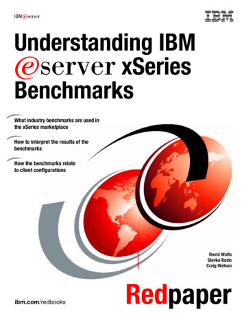
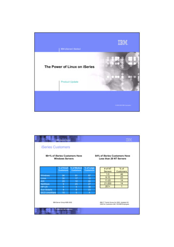
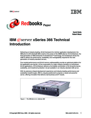
Overview of the x366The key features of the x366 include: Four-way capable server in a rack-dense 3U form factor. IBM Eserver X3 Architecture, the XA-64e third-generation chipset. Models with one Intel Xeon MP processor, up to 3.66 GHz and 1 MB L2 cache, whichcan be upgraded to four-way. Processors support 64-bit addressing with the IntelExtended Memory 64 Technology (EM64T) architecture. Memory: 2 GB standard expandable to 64 GB (with 4 GB DIMMs), usinghigh-performance PC2-3200 ECC DDR2 DIMMs. Active Memory with Memory ProteXion, memory mirroring, memory hot-swap andhot-add, and ChipKill. Six full-length 64-bit 266 MHz PCI-X 2.0 Active PCI slots. Integrated Adaptec AIC-9410 serial-attached SCSI (SAS) controller. Support for internalRAID arrays using an optional ServeRAID -8i adapter. ServeRAID-6M is also supportedfor external SCSI storage, with the EXP400 enclosure. Six internal hot-swap drive bays for up to 440 GB of internal storage (using 73.4 GBdisks). Integrated Dual-port Broadcom 5704 PCI-X Gigabit Ethernet. Baseboard Management Controller standard with optional Remote Supervisor Adapter IISlimLine adapter. Supports the IBM Integrated xSeries Adapter for iSeries (IXA) for a direct high-speedlink to an iSeries server. Three-year warranty, on-site, nine hours per day, five days per week, with a next businessday response. The x366 is targeted at ERP, database, e-mail, and e-commerce applications.Figure 2 shows the x366 and major components on the front of the unit.Six hot-swapdisk drivebaysUSB portProcessor tray(behind bezel)Figure 2 Front panel of the x3662IBM Eserver xSeries 366 Technical IntroductionOperatorpanelPanel releasebutton to displaylight path panelDVD-ROMdrive
Dual-core capability: In addition to the single-core Xeon processors MP available today,strategic intent of IBM is to support dual-core microprocessor technology on the x366server at such a time that this technology becomes generally available from our partners.The strategic intent also includes releasing a dual-core upgrade option kit to enablecustomers to upgrade from single-core to dual-core technology in the future. In both cases,this support may require updated server components made available in future revisions ofthe x366.Current modelsTable 1 shows the x366 models that were announced in March 2005.Table 1 x366 models announced in March 2005ModelStandard/max CPUL2 cacheL3 cacheStandard/max memory8863-1RY1x 3.16 GHz Xeon MP / 41 MBNone2 GB (2x 1 MB) / 648863-2RY1x 3.66 GHz Xeon MP / 41 MBNone2 GB (2x 1 MB) / 64Note: x366 Express models are also available in some geographies. These systems haveadditional processors, memory, disk, or a second power supply standard. Consult yoursales representative for more information.The x366 supports one, two, three, or four processors.Both models support a maximum of 64 GB using 4 GB DIMMs in 16 sockets. To achieve themaximum, you will need to install three additional memory cards (one four-socket card isstandard), remove the standard pair of 1 GB DIMMs and insert 16 DIMMs.The x366 has six internal PCI-X 2.0 slots. Unlike the x365, the x366 does not support theattachment of an RXE-100 Remote Expansion Enclosure. The RSA II SlimLine andServeRAID-8i options do not use any of these six PCI-X slots.IBM XA-64e third-generation chipsetThe x366 uses the third generation of the IBM XA-64e chipset. The architecture consists ofthe following components: One to four Xeon MP processors One Hurricane Memory and I/O Controller (MIOC) Two Calgary PCI BridgesFigure 3 on page 4 shows the block diagram of the x366.IBM Eserver xSeries 366 Technical Introduction3
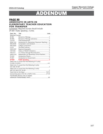
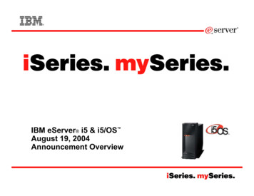
CPU 1CPU 2667 MHz5.33 GBpsDDR2SMI2DDR2SMI2DDR2SMI2DDR2SMI2Each:667 MHz5.33 GBpsPCI-X bridge33 66CPU 4667 MHz5.33 GBpsMemorycontroller6 GBpsCalgaryCPU 3IBM XA-64ecore chipsetHurricane6 GBps6 GBpsPCI-X bridge266 266 MHz266 MHzVideoRSA SL1USB 6HDDbackplaneGigabitEthernetSix PCI-X 2.0 slots:64-bit 266 MHzFigure 3 xSeries 366 system block diagramEach memory port out of the memory controller has a peak throughput of 5.33 GBps. DIMMsare installed in matched pairs (that is, two-way interleaving) to ensure that the memory port isfully utilized. Peak throughput for each PC2-3200 DDR2 DIMM is 2.67 GBps. (The DIMMs arerun at 333 MHz to remain in sync with the throughput of the front-side bus.)In addition, there are four memory ports; spreading installed DIMMs across all four memoryports can improve performance, because the four independent memory ports (memory cards)provide simultaneous/concurrent access to memory. With four memory cards installed (andDIMMs in each card), peak memory bandwidth is 21.33 GBps.The memory controller routes all traffic from the four memory ports, two CPU ports and thetwo PCI bridge ports. The memory controller also has embedded DRAM, which in the x366holds a snoop filter lookup table. This filter ensures that snoop requests for cache lines go tothe appropriate CPU bus and not both of them, thereby improving performance.One PCI bridge supplies four of the six 64-bit 266 MHz PCI-X slots on four independentPCI-X buses. The other PCI bridge supplies the other two PCI-X slots (also 64-bit, 266 MHz),plus all the onboard PCI devices, including the optional ServeRAID-8i and RemoteSupervisor Adapter II SlimLine daughter cards.Figure 4 on page 5 shows the rear panel of the x366.4IBM Eserver xSeries 366 Technical Introduction
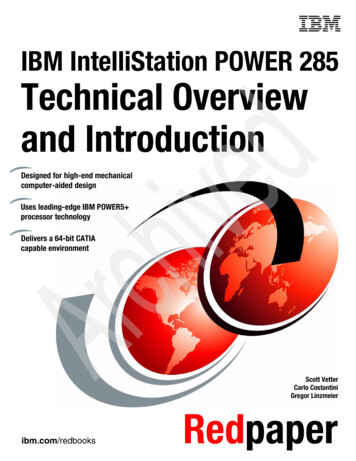
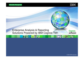
Service processorEthernet portSystem serial portService processorserial port2x USBMouseKeyboardVideo2x GigabitEthernetIXA RS-485(not service processor)Figure 4 Rear view of the x366ProcessorsThe x366 models use the Intel Xeon Processor MP with EM64T extensions (“Cranford”).Models of the x366 come with one processor installed. One, two, three, or four processorsare supported. Installed processors must be identical in speed and cache size. There arecurrently two x366 models, as listed in Table 2. Both models support one, two, three, or fourprocessors.Table 2 Processors used in the x366 modelsModelProcessorL2 cacheL3 cacheInstalledMaxUpgrade option8863-1RYXeon MP 3.16 GHz1 MB0 MB1413N06948863-2RYXeon MP 3.66 GHz1 MB0 MB1413N0695The upgrade options include one processor and one VRM. The VRM must be installed if theoption is to be installed as CPU 3 or CPU 4. The VRMs for CPUs 1 and 2 are integrated ontothe processor board. See the x366 Installation Guide for more details.The processors are easily accessible from the front of the server on a sliding tray.IBM Eserver xSeries 366 Technical Introduction5
OFR1NTOFR2NTOFR3NT4The processor tray pulls outfrom the front of the serverand houses the CPUs,VRMs, and memorycontroller.Figure 5 x366 processor trayThe “Cranford” Xeon MP processor has two levels of cache on the processor die: L2 cache is 1 MB in size. The L2 cache implements the Advanced Transfer Cachetechnology, which means L2-to-processor transfers occur across a 256-bit bus in only oneclock cycle. L1 execution trace cache is used to store micro-operations (that is, decoded executablemachine instructions); it serves those to the processor at rated speed. This additional levelof cache saves decode time on cache hits.Key features of the processors used in the x366 include: 667 MHz front-side busThe Pentium III Xeon processor in older servers had a 100 MHz front-side bus thatequated a burst throughput of 800 MBps. With protocols such as TCP/IP, this has beenshown to be a bottleneck in high-throughput situations.The “Cranford” Xeon Processor MP improves on this by using two 133 MHz clocks, out ofphase with each other by 90 and using both edges of each clock to transmit data. This isshown in Figure 6.133 MHz clock A133 MHz clock BFigure 6 Quad-pumped frontside busThis increases the performance of the frontside bus without the difficulty of high-speedclock signal integrity issues. Because the bus is 8 bytes wide, the end result is an effectiveburst throughput of 5.33 GBps, which can have a substantial impact, especially onTCP/IP-based LAN traffic.6IBM Eserver xSeries 366 Technical Introduction
Hyper-ThreadingHyper-Threading Technology enables a single physical processor to execute two separatecode streams (threads) concurrently. To the operating system, a processor withHyper-Threading appears as two logical processors, each of which has its ownarchitectural state (that is, its own data, segment, and control registers) and its ownadvanced programmable interrupt controller (APIC).Each logical processor can be individually halted, interrupted, or directed to execute aspecified thread, independent of the other logical processor on the chip. Unlike atraditional two-way SMP configuration that uses two separate physical processors, thelogical processors share the execution resources of the processor core, which include theexecution engine, the caches, the system bus interface, and the firmware.Figure 7 outlines the basic layout of a Hyper-Threading-enabled CPU, where you can seethat only the components for the architectural state of the CPU have doubled.Physical processorArchitectural -ThreadingLogical ProcessingresourcesProcessor withHyper-ThreadingFigure 7 The architectural differences of a Hyper-Threading enabled processor versus anon-Hyper-Threading processorNote: Hyper-Threading is enabled by default on the x366, but can be easily disabled inthe BIOS.Hyper-Threading Technology is designed to improve server performance by exploiting themulti-threading capability of operating systems, such as Windows 2003 and Linux , andserver applications, in such a way as to increase the use of the on-chip executionresources available on these processors.Fewer or slower processors usually achieve the best gains from Hyper-Threadingbecause there is a greater likelihood that the software can spawn sufficient numbers ofthreads to keep both paths busy. The following performance gains are likely:– Two physical processors: up to approximately 25% performance gain– Four physical processors: up to approximately 15% performance gain– Eight physical processors: up to approximately 10% performance gainTests have shown that software often limits SMP scalability, but customers should expectimproved results as software matures. Best-case applications today are:– Databases– Java IBM Eserver xSeries 366 Technical Introduction7
– Web servers– E-mailNote that Microsoft licensing of the Windows 2000 Server operating systems is bynumber of processors (four-way for Server, eight-way for Advanced Server, 32-way forDatacenter Server). Therefore, the appearance of twice as many logical processors canpotentially affect the installation of the operating system.Windows Server 2003 understands the concept of physical processors versus logicalprocessors. For more information about Hyper-Threading, see the following Web tion/performance/reports/hyperthread.asp Extended Memory 64 Technology (EM64T)First introduced in the Xeon DP “Nocona” processor, EM64T is a 64-bit extension to theindustry standard IA32 32-bit architecture. EM64T adds:– A set of new 64-bit general purpose registers (GPR)– 64-bit instruction pointers– The ability to process data in 64-bit chunksEven though the names of these extensions suggest that the improvements are simply inmemory addressability, Intel EM64T is in fact a fully functional 64-bit processor.Tip: For all intents and purposes, Intel EM64T and AMD AMD64 are identical.To reap the full benefit of this technology, you need to have a 64-bit operating system and64-bit applications that have been recompiled to take full advantage of this architecture.Existing 32-bit applications running on a 64-bit operating system can also benefit fromEM64T.The “Cranford” processor limits memory addressibility to 36 bits of addressing.There are three distinct operation modes available in EM64T:– 32-bit legacy modeThe first and, in the near future, probably most widely used mode will be the 32-bitlegacy mode. In this mode, EM64T processors will act just like any other IA32compatible processor. You can install your 32-bit operating system on such a systemand run 32-bit applications, but you will not be able to make use of the new featuressuch as the flat memory addressing above 4 GB or the additional General PurposeRegisters (GPRs). 32-bit applications will run just as fast as they would on any current32-bit processor.Most of the time, IA32 applications will run even faster because of numerous otherimprovements that boost performance regardless of the maximum address size.– Compatibility modeThe second mode supported by EM64T is the compatibility mode, which is anintermediate mode of the full 64-bit mode described below. To run in compatibilitymode, you will need to install a 64-bit operating system and 64-bit drivers. If a 64-bitOS and drivers are installed, the processor will be enabled to support both 32-bitapplications and 64-bit applications.The compatibility mode gives you the ability to run a 64-bit operating system while stillbeing able to run unmodified 32-bit applications. Each 32-bit application will still belimited to a maximum of 4 GB of physical memory. However, the 4 GB limit is nowimposed on a per-process level, not on a system-wide level. This means that every8IBM Eserver xSeries 366 Technical Introduction
32-bit process on this system gets its very own 4 GB of physical memory space(provided sufficient physical memory is installed). This is already a huge improvementcompared to IA32, where the operating system kernel and the application had to share4 GB of physical memory.Additionally, the compatibility mode does not support the virtual 8086 mode, soreal-mode legacy applications are not supported. However, 16-bit protected modeapplications are supported.– Full 64-bit modeThe final mode is the full 64-bit mode. Intel refers to it as the IA-32e mode (AMD refersto this as the long mode). This mode is applied when a 64-bit operating system and64-bit application are used. In the full 64-bit operating mode, an application can have avirtual address space of up to 40 bits (which equates to 1 TB of addressable memory).The amount of physical memory is determined by how many DIMM slots the server hasand the maximum DIMM capacity supported and available at the time.Applications that run in full 64-bit mode will have access to the full physical memoryrange (depending on the operating system), and to the new GPRs and the expandedGPRs. However, it is important to understand that this mode of operation requires notonly a 64-bit operating system (and, of course, 64-bit drivers) but also a 64-bitapplication that has been recompiled to take full advantage of the variousenhancements of the 64-bit addressing architecture.For more information about the features of the Xeon Processor MP, refer f/For more information about EM64T, s/XceL4v Dynamic Server CacheAn XceL4 Dynamic Server Cache serves two purposes in the X3 Architecture servers (thex260, x366, and x460): A snoop filter lookup table to reduce traffic on the front side bus (all three servers) A cache for multi-node configurations to reduce latency across the scalability cables inx460 configurations (x460 servers only)With advances in chip design, IBM has now reduced the latency of main memory to belowthat of the XceL4 cache in the x445. In other words, the time it takes to access data directlyfrom memory is almost as fast as accessing it from L3. As a result, on a four-way system suchas the x366, there is little or no need for either a L3 cache or L4 cache (as implemented in theXceL4v).Since the L3 cache is inline, when cache misses do occur, it adds significant overhead tomemory access. The L3 cache rate has to be very high for it to keep up with the 3.66 GHzprocessor. In most server applications with multiple users, the threads competing for L3cache generate a lower hit rate, and the latency of the L3 drops performance. The sameapplies to any L4 cache.As a result, there is no performance benefit in implementing neither L3 nor L4 cache on thefour-way x366. For these reasons there is 0 MB of XceL4v cache on the x366 server.IBM Eserver xSeries 366 Technical Introduction9
The XceL4v also functions as a snoop filter lookup table to reduce traffic on the front side bus.Its embedded DRAM (eDRAM) stores a directory of all processor cache lines to minimizesnoop traffic on the dual front-side buses and minimize cache misses.System memoryThe models of the x366 have a 2 GB standard, implemented as two 1 GB PC2-3200 ECCDDR2 DIMMs.Memory is implemented in the x366 using memory cards. Each card has four DIMM sockets.One memory card is standard and the x366 supports up to four memory cards. Using 4 GBDIMMs in every socket (that is, a total of 16 DIMMs), the server can hold 64 GB of RAM.The memory is two-way interleaved (meaning that memory DIMMs are installed in pairs). Asshown in Figure 3 on page 4, there are four ports to memory, with each supporting up to5.33 GBps data transfers.The DIMMs operate at 333 MHz (instead of 400 MHz as for the PC2-3200 spec) so thatthroughput is 2.67 GBps (333 MHz x 8 bytes). At 2.67 GBps and two-way interleaving, thethroughput matches that of the front-side bus at 5.3 GBps so that bus transfers remain insync.The x366 comes standard with one memory card and two 1 GB DIMMs. Memory is registeredECC DDR2 memory meeting the PC2-3200 standard. Up to four memory cards aresupported, and each memory card can hold two or four DIMMs. (DIMMs must be installed inmatched pairs.)By adding three additional memory cards (part number 13M7409) and using 4 GB DIMMs(replacing the standard pair of 1 GB DIMMs), the x366 can be expanded to 64 GB.Important: There must be at least one memory card with one matched pair of DIMMsinstalled for the server to operate. Each memory card requires at least one matched pair ofDIMMs.10IBM Eserver xSeries 366 Technical Introduction
When the cover and bezel are removed, the memory cards are easily accessible (Figure 8).In order to replace or add any DIMM, you need to remove the memory card. See “Memorymirroring” on page 13 and “Hot-add memory” on page 15, to see how this can be done evenwhile the system and the operating system are up and running.Each memory card has fourDIMM sockets. DIMMs mustbe installed in matchedpairs.The x366 has onememory card standardand supports up to fourcards.Two 1 GB DIMMs areinstalled standard in card 1.Memory cards can behot-swapped orhot-added (specificrestrictions apply).DCACFigure 8 x366 memory card and locationKey configuration rules: Because the x366 uses two-way interleaving memory, DIMMs must be installed inmatched pairs. Supported DIMM options are:– 2 GB (part number 73P2866) containing two 1 GB DIMMs– 4 GB (part number 73P2867) containing two 2 GB DIMMs– 8 GB (part number 30R5145) containing two 4 GB DIMMs Memory cards have part number 13M7409. One is standard and up to four can beinstalled. Each memory card has four DIMM sockets. There are two ways to fill the DIMMs sockets, depending on whether cost or performanceis the more important consideration:– Cost-effective configuration: To minimize cost, you can install the memory DIMMs byfilling each memory card before adding DIMMs to the next memory card.– Performance-optimized configuration: As described in “IBM XA-64e third-generationchipset” on page 3, there are four independent memory ports. Therefore, to optimizeperformance, you can spread the DIMMS (still installed in matched pairs) across allfour memory cards, before filling each card with two more DIMMs.IBM Eserver xSeries 366 Technical Introduction11
A more detailed description and the exact sequence for installation can be found in thexSeries 366 User’s Guide. If you want to install the full 64 GB, you must remove the existing 1 GB DIMMs and fullypopulate the x366 with four memory cards, each with four 4 GB DIMMs.Several advanced features are implemented in the x366 memory subsystem, collectivelyknown as Active Memory: Memory ProteXionThe Memory ProteXion feature (also known as redundant bit steering) provides theequivalent of a hot-spare drive in a RAID array. It is based in the memory controller, and itenables the server to sense when a chip on a DIMM has failed and to route the dataaround the failed chip.Normally, 128 bits out of every 144 are used for data and the remaining 16 bits are usedfor ECC functions. However, the x366 needs only 12 bits to perform the same ECCfunctions, thus leaving 4 bits free. These 4 bits are equivalent to an x4 memory chip on theDIMM, which Memory ProteXion uses. In the event that a chip failure on the DIMM isdetected by memory scrubbing, the memory controller can re-route data around that failedchip through these spare bits.It can do this automatically without issuing a Predictive Failure Analysis (PFA) or lightpath diagnostics alert to the administrator (although an event is logged to the serviceprocessor log). After the second DIMM failure, PFA and light path diagnostics alerts wouldoccur on that DIMM as normal.Note: In BIOS, there is a Memory Array setting in Advanced Settings. When it is set toHigh Performance Memory Array, BIOS reconfigures the server for maximumperformance at the expense of some fault tolerance features, including MemoryProteXion. For a production environment, we recommend that you do not select thissetting, thereby keeping your system protected from memory failures with MemoryProteXion. Memory scrubbingMemory scrubbing is an automatic daily test of all of the system memory that detects andreports memory errors that might be developing before they cause a server outage.Memory scrubbing and Memory ProteXion work in conjunction with each other and do notrequire memory mirroring to be enabled to work properly.When a bit error is detected, memory scrubbing determines whether the error isrecoverable. If it is recoverable, Memory ProteXion is enabled and the data that was storedin the damaged locations is rewritten to a new location. The error is then reported so thatpreventive maintenance can be performed. As long as there are enough good locations toallow the proper operation of the server, no further action is taken other than recording theerror in the error logs.If the error is not recoverable, then memory scrubbing sends an error message to the lightpath diagnostics, which turns on the proper lights and LEDs to guide you to the damagedDIMM. If memory mirroring is enabled, then the mirrored copy of the data from thedamaged DIMM is used until the system is powered down and the DIMM is replaced. Memory mirroringMemory mirroring is roughly equivalent to RAID-1 in disk arrays, in that usable memory ishalved and a second copy of data is written to the other half. If 8 GB is installed, then theoperating system sees 4 GB when memory mirroring is enabled. (It is disabled in the BIOS12IBM Eserver xSeries 366 Technical Introduction
by default.) Because all mirroring activities are handled by the hardware, memorymirroring is operating system independent.When memory mirroring is enabled, certain restrictions exist with respect to placementand size of memory DIMMs and the placement and removal of memory cards. Thesetopics are discussed in “Memory mirroring” on page 13. Chipkill memoryChipkill is integrated into the XA-64e chipset, so it does not require special Chipkill DIMMsand is transparent to the operating system. When combining Chipkill with MemoryProteXion and Active Memory, the x366 provides very high reliability in the memorysubsystem.When a memory chip failure occurs, Memory ProteXion transparently handles thererouting of data around the failed component as described above. However, if a furtherfailure occurs, the Chipkill component in the memory controller reroutes data. Thememory controller provides memory protection similar in concept to disk array striping withparity, writing the memory bits across multiple memory chips on the DIMM. The controllercan reconstruct the “missing” bit from the failed chip and continues working as usual. Oneof these additional failures can be handled per memory port (a total of four Chipkillrecoveries). Hot-add and hot-swap memoryThe x366 supports the replacing of failed DIMMs while the server is still running. Thishot-swap support works in conjunction with memory mirroring. The server also supportsadding additional memory while the server is running. Adding memory requires operatingsystem support.These two features are mutually exclusive. Hot-add requires that memory mirroring bedisabled and hot-swap requires that memory mirroring be enabled. These features arediscussed in “Hot-swap memory” on page 14 and “Hot-add memory” on page 15.In addition, to maintain the highest levels of system availability, if a memory error is detectedduring POST or memory configuration, the server can automatically disable the failingmemory bank and continue operating with reduced memory capacity. You can manuallyre-enable the memory bank after the problem is corrected by using the Setup menu in theBIOS.Memory mirroring, Chipkill, and Memory ProteXion provide multiple levels of redundancy tothe memory subsystem. Combining Chipkill with Memory ProteXion allows up to two memorychip failures per memory port on the x366, for a total of eight failures sustained.1. The first failure detected by the Chipkill algorithm on each port does not generate a lightpath diagnostics error, as Memory ProteXion recovers from the problem automatically.2. Each memory port could then sustain a second chip failure without shutting down.3. Provided that memory mirroring is enabled, the third chip failure on that port would sendthe alert and take the DIMM offline, but keep the system running out of the redundantmemory bank.Memory mirroringMemory mirroring is available on the x366 for increased fault tolerance. Memory mirroring isoperating system independent, since all mirroring activities are handled by the hardware.IBM Eserver xSeries 366 Technical Introduction13
To understand what memory mirroring and hot-swap capabilities exist with the server, youmust first understand how the memory cards are powered. The x366 has two separatememory power buses that are split between the four memory cards. As shown in Figure 9,memory cards 1 and 2 are on power bus 1, and memory cards 3 and 4 are on power bus 2.Four memory cards(card 1 standard)Power bus 1(cards 1 & 2)Hot-swapenabled LED12Memory portpower LEDDIMMSocket 134Power bus 2(cards 3 & 4)DIMMSocket 4Each card hasfour DIMM socketsCard 1 has sockets1 and 3 filled with1 GB DIMMsFigure 9 Memory hardware on the x366Mirroring takes place across the two power buses. In other words, the memory DIMMs incards 1 and 2 are mirrored to the memory DIMMs in cards 3 and 4. With memory mirroringenabled in BIOS, you can hot-swap one memory card at a time on each memory power bus.Once memory mirroring is enabled, the data that is written to memory will be stored in twolocations. For read operations, data is read from the DIMMs with the least amount of reportedmemory errors through memory scrubbing.Memory scrubbing is an automatic and regular test of all the system memory that detects andreports memory errors before they cause a server outage. If memory scrubbing determinesthat the DIMM is damaged beyond use, read and write operations are redirected to theremaining good DIMM. Memory scrubbing then reports the damaged DIMM and the light pathdiagnostic displays the error. If memory mirroring is enabled, then the mirrored copy of thedata from the damaged DIMM is used until the system is powered down and the DIMMreplaced. After the damaged DIMM is replaced, memory mirroring will copy the mirrored databack onto the new DIMM.Key configuration rules relating to memory mirroring are as follows: Memory mirroring must be enabled in the BIOS (it is disabled by default). Both memory cards must have the same total amount of memory, and must have identicalDIMMs. In other words, DIMMs must be installed in matched quads to support memorymirroring. Partial mirroring is not supported. See the x366 Installation Guide forinformation about the exact installation order required.Important: Because of memory mirroring, you will only have half of the total amount ofmemory available. If 8 GB is installed, for example, then the operating system sees 4 GBonce memory mirroring is enabled (it is disabled in the BIOS by default).Hot-swap memoryThe x366 supports hot-swap memory, which mea
2 IBM Eserver xSeries 366 Technical Introduction Overview of the x366 The key features of the x366 include: Four-way capable server in a rack-dense 3U form factor. IBM Eserver X3 Architecture, the XA-64e third-generation chipset. Models with one Intel Xeon MP processor, up to 3.66 GHz and 1 MB L2 cache, which can be upgraded to four-way.