Transcription
Improving the Efficiency of Cooling in theHeadendA Technical Paper prepared for SCTE/ISBE byJim Farmer, Co-Author, Consultant to the Cable TV Industry, SCTE/ISBE Member2406 Stoney Point RoadCumming, GA 30041jofarmer@mindspring.com(678) 640-0860David Kozischek, Co-Author, Corning Optical Communications800 17th Street NWHickory, NC 28603David.Kozischek@corning.com(828) 901-5902 2016 Society of Cable Telecommunications Engineers, Inc. All rights reserved.
Table of ContentsTitlePage NumberTable of Contents 21. Introduction 32. Organizing to Save Energy 33. The Top 12 34. Technologies that Save You Energy (Opportunity 5) 45. The Cost of Removing Heat 56. Some Numerical Examples 67. Moving Heat to the Node 88. Hot Aisle/Cold Aisle Layout (Opportunity 6) 99. Containment/Enclosures (Opportunity 7) 1010. Variable Speed Fan Drives (general airflow issues) (Opportunity 8) 1111. Effect of Reducing Cooling Air Speed 1112. Reducing the Resistance to Airflow 1113. Advantages of Fiber in the Headend 1214. Conclusions 1315. Appendix: The Difference Between Headends and Hubs 1316. References 15List of FiguresTitlePage NumberFigure 1. 10 Gb/s Operating Cost, Fiber vs Copper4Figure 2. Moving RF Modulators and Demodulators to the Node (only modulation shown forsimplicity)8Figure 3. Hot Aisle/Cold Aisle Concept9Figure 4. Hot Air Containment System (Chatsworth)10Figure 5. Enclosed non-heat-producing equipment helps prevent air leakage10Figure 6. Size comparison of fiber and reduced-size CAT6A bundles11Figure 7. Simulation of airflow around copper and fiber cabling12Figure 8. Headends and Hubs in Cable TV Plant14List of TablesTitlePage NumberTable 1. Example Annual Costs of Power, Not Including Heat Removal6Table 2. Example Annual Costs of Power, Including Heat Removal7 2017 Society of Cable Telecommunications Engineers, Inc. All rights reserved.2
1. IntroductionHeadends and hubs are getting more sophisticated, with more video options, much more data handling,and telephone soft switches. With this increased sophistication comes more power consumption, whichcan cause problems to arise. Some electronic equipment is rated for long-term operation at a maximumtemperature as low as about 100 degrees Fahrenheit. As switches, servers, and other equipment haveevolved, the pressures on cooling have gotten much more severe. A one-rack-unit (1RU) edge QAMchassis, for example, may be rated to consume about 200 watts. Imagine two 100 watt incandescent lightbulbs in this 1RU (1.75 inch) rack – that’s a lot of heat! Stand behind a “big iron” (high port count) cablemodem termination system (CMTS) loaded to maximum capacity and feel the air exhaust temperature.Cooling of a headend is not unlike cooling of a data center except there is a plethora of different types ofequipment with different cooling strategies. Also, while many data centers have raised floors throughwhich they can channel cooled air to each rack, most headends tend to use overhead cabling (a trend indata centers, too), with less capability for handling airflow. While data centers also experience expansionwith time, many headends and hubs were built in a different era when power density was not nearly sohigh, and cooling was easier. Air conditioning was deployed that matched the amount of power beingconsumed and the cooling problem was averted. Today every cooling dollar needs to work as hard asevery other dollar spent on infrastructure.Let’s see if lessons can be learned from data centers, and see how we might apply them to headends andhubs (we’ll just say headend, but obviously we are including hubs that have similar coolingrequirements). According to IDC, up to 60 percent of downtime can be directly attributed to electronicfailures due to excessive heat, so addressing heat loads has very beneficial effects. In this paper, we willzero in on a few key issues.2. Organizing to Save EnergyEnergy savings opportunities are in a number of places; however the greatest energy savings happenswith the involvement and support of top management. Many successful programs (SCTE 234 or ISO50001 for example) have been implemented by energy teams who report directly to the board of directorsor a high-ranking officer of the company. Management needs to put a priority on efficient cooling,including guidance to the energy team as to what type of payback period is expected. A reasonablecriterion might be a 3-year payback for an investment in energy savings. When considering the paybackperiod, don’t forget the cost of heat removal (air conditioning) as well as heat generation. Depending onlocal power costs and the air conditioning efficiency, removing the heat may cost more than generating itin the first place. As a general rule, the EPA says that for every unit of electronics power, an equal unit isrequired for cooling. Some references state even more power is required for cooling.3. The Top 12According to the EPA Energy Star Program, the top 12 opportunities to save energy and hence money ina data center arei: 2017 Society of Cable Telecommunications Engineers, Inc. All rights reserved.3
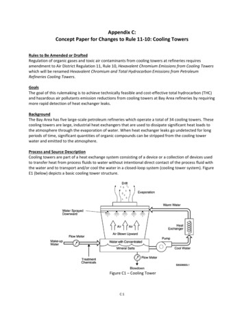
1. Server virtualization (This is big: virtualization results in higher server utilization, more processpower, and fewer servers.)2. Decommissioning of unused servers3. Consolidation of lightly utilized servers4. Better management of data storage5. Purchasing more energy-efficient servers, UPSs, and PDUs6. Hot aisle/cold aisle layout7. Containment/enclosures8. Variable-speed fan drives (general airflow issues)9. Properly deployed airflow management devices10. Server inlet temperature and humidity adjustments11. Air-side economizer12. Water-side economizerIn this paper, we will concentrate on opportunities 5-8. The website referenced (end note 1) has manyresources to get you thinking about how to save energy and hence money. Some of these opportunitieswill possibly not apply to your headend, but others will. A lot can be learned from studying theexperiences in data centers. The applicability of certain measures may also depend on location: the issuesare different in a dry desert climate than in a humid seaside resort, but saving energy/money is a universalgoal.4. Technologies that Save You Energy (Opportunity 5)Example: You have a few servers and switches in your headend, maybe not as many as in a large datacenter, but some. Ask, how old they are, and how do they stack up in terms of energy efficiency withnewer products? Is there a way you can let some go to sleep during off hours, when your subscribers aredemanding fewer server-based services? Some operating systems allow for running the processors at aslower speed when the demand on them is not great,resulting in lower power dissipation. Some canconsolidate functions on a fraction of the processorcores available, putting the unused cores to sleepwhen they are not needed.There are choices, in many cases, of interconnectingequipment with either fiber or copper cabling. We’llhave more to say later about the merits of each, butright now let’s talk about the relative merits of thetransmitters and receivers in the routers, servers, andCMTSs. Figure 1 indicates an estimate of the powerdraw of each technology based on a single 10 Gb/sFigure 1. 10 Gb/s Operating Cost, Fiber vs Copperlink. Fiber transceivers are lower in powerconsumption, which not only saves money in operating the equipment, but saves a similar amount incooling costs. 2017 Society of Cable Telecommunications Engineers, Inc. All rights reserved.4
Opportunity: There are certainly potential savings in UPSs and power distribution units (PDUs). It iscommon to use battery-based uninterruptible power supplies to bridge the time between a power failureand when the generator can start then carry the load. Have you looked recently to see if there are moreefficient units on the market? If you are in the market for UPSs, are you comparing the total operatingcost (which includes efficiency) of the candidate UPSs? You have probably added a lot more equipmentto your headend in the years since you purchased your last UPS. Is it capable of handling the load youwould present to it today? Same for your generator: if you need it, will it be capable of handling today’sload?Opportunity: Some PDUs step down voltage for distribution to rack-based power distribution units. Howefficient are the transformers? How efficient are the rectifiers where AC is converted to DC? Howefficient are the voltage regulators? When you get to 48 vdc distribution, you are dealing with a LOT ofcurrent. Is your wiring sufficiently sized to handle the current without creating power-robbing voltagedrop? These issues can develop over years, as more equipment is added. You have probably experiencedthe same thing at home: you are using more power than you did maybe 20 years ago, even thoughequipment has gotten more efficient. This is simply because you have more equipment. And much of thatequipment consumes so-called “phantom power,” using power even when turned off. To an extent, thesame goes for your headend. In particular, UPSs use some power when not in use, to keep the batteryfloat charged and to monitor power, to be ready to start when needed.5. The Cost of Removing HeatSeveral anecdotal reports place the cost of removing heat from a data center or headend, at nearly thesame as the cost of operating the equipment. This is a sufficient cost to persuade companies to exploreunconventional heat removal techniques. For example, IEEE recently reported that Microsoft has built anexperimental underwater data center, which drives the heat removal cost down from maybe 90 percent ofthe server powering cost to about 3 percent.ii 2017 Society of Cable Telecommunications Engineers, Inc. All rights reserved.5
6. Some Numerical ExamplesTable 1. Example Annual Costs of Power, Not Including Heat Removal#connections:100200300Power cost10 Gb/s links10 Gb/s links10 Gb/s linksCopperFiberCopperFiberCopperFiber 0.070 184 61 368 123 552 184 0.075 197 66 394 131 592 197 0.080 210 70 421 140 631 210 0.085 224 75 447 149 671 224 0.090 237 79 473 158 710 237 0.095 250 83 500 167 749 250 0.100 263 88 526 175 789 263 0.105 276 92 552 184 828 276 0.110 289 96 579 193 868 289 0.115 302 101 605 202 907 302 0.120 316 105 631 210 947 316 0.125 329 110 657 219 986 329 0.130 342 114 684 228 1,026 342per kWHWe can estimate the cost of transferring data on copper or fiber cables by looking at some scenariosinvolving the number of links you have and the cost of power in your area. Table 1 illustrates the cost ofsimply operating either fiber (utilizing lightwaves) or copper (utilizing electron flow) interfaces, withoutregard for the cost of power supply inefficiency, the cost of heat removal, or the cost of additional 2017 Society of Cable Telecommunications Engineers, Inc. All rights reserved.6
blockage of moving air due to cable blockage. Table 2 assumes a rule-of-thumb air conditioning cost of100 percent of the power consumed by the equipment. Heat generated by fiber interfaces are lower thanthe heat generated by copper interfaces. As of December 2016 the average commercial power cost in theUS was about 10.5 cents per kWH.iii The cost ranged from about 0.5 to 12 cents per kWH, depending onlocation.ivTable 2. Example Annual Costs of Power, Including Heat Removal#connections:100200300Power cost10 Gb/s links10 Gb/s links10 Gb/s linksCopperFiberCopperFiberCopperFiber 0.070 368 123 736 245 1,105 368 0.075 394 131 789 263 1,183 394 0.080 421 140 842 281 1,262 421 0.085 447 149 894 298 1,341 447 0.090 473 158 947 316 1,420 473 0.095 500 167 999 333 1,499 500 0.100 526 175 1,052 351 1,578 526 0.105 552 184 1,105 368 1,657 552 0.110 579 193 1,157 386 1,736 579 0.115 605 202 1,210 403 1,815 605 0.120 631 210 1,262 421 1,893 631 0.125 657 219 1,315 438 1,972 657 0.130 684 228 1,367 456 2,051 684per kWH 2017 Society of Cable Telecommunications Engineers, Inc. All rights reserved.7
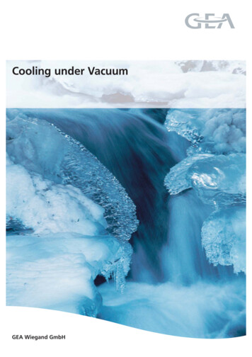
7. Moving Heat to the NodeFigure 2. Moving RF Modulators and Demodulators to the Node (only modulation shown for simplicity)There has been a lot of interest in moving the QAM modulators to the node, particularly but not totallyapplied to modem systems. This Remote PHY (for remote physical layer) has advantages in terms of costand some overall power savings, as well as removing some power-hungry equipment from the headendand making some incremental improvement in the quality of signals delivered to the coax plant. However,to an extent you are moving heat from a headend, where you have active heat removal equipment, to anode, where you have only passive heat removal and a more hostile temperature environment.Figure 2a illustrates the old way, with RF modulation and demodulation in the CMTS (and in otherequipment). What is desired is to move the modulators to the node. While not primarily seen as a powersaving feature (the overall savings are minimal), it does reduce power demand somewhat in the headendby moving out the relatively power-hungry modulation and demodulation processes, and exchanging thelinear electrical-to-optical and optical-to-electrical conversion processes to lower power and cheaperbinary processes. The downside is more heat moves to the node, which has traditionally been a problem 2017 Society of Cable Telecommunications Engineers, Inc. All rights reserved.8
to keep cool, and the timing issues involved in separating the RF from other CMTS functions has createda number of headaches for equipment designers.Proposals are available that move even more heat-producing circuitry out of the headend, but so far as weknow, they are not under active development at time of publication.8. Hot Aisle/Cold Aisle Layout (Opportunity 6)Most equipment needingactive cooling takes air infrom one side and expels it tothe other side of theequipment. It is common forequipment to take in air fromthe front side and expel it tothe rear. This leads to theconcept of hot aisle/coldaisle, as illustrated in Figure3. A cold aisle is formedbetween rows of equipmentracks by forcing cold airfrom the air conditioningsystem (computer room airFigure 3. Hot Aisle/Cold Aisle Conceptconditioning or CRAC)between the rows. Equipment is installed such that it always draws air in from the cold aisle(s) and expelsit to the hot aisle(s) on the other side, where it is returned to the CRAC. This improves the efficiency ofthe air conditioning by making sure that the cold air goes where it does the most good. In some casescontainment (of either hot or cold air) is employed to prevent the cold and hot air from mixing, reducingthe efficiency of the process.The figure assumes a raised floor, which can act as a duct for the cold air. We call such an arrangement aplenum. If you don’t have a raised floor, there are other ways to get cold air to the cold aisle. You can useconventional overhead ducting to get the cold air to the cold aisle. There are also CRAC units that fit in arow of racks as just another rack, taking air in from the hot side and expelling the cooled air to the coldaisle.If equipment, such as many “big iron” CMTSs, takes in air in front and expels it to the rear, then the frontside will face the cold aisle. If you have a piece of gear that pulls in air from the rear and expels it to thefront, then of course the opposite mounting is employed. We have seen equipment that takes air in on oneside and expels it on the other. In this case, baffles will need to be used to direct the air properly.Some older and less power-dense equipment may use passive cooling rather than active (fan) cooling.Such equipment may locate most heat-producing components near the rear, but it may not. Since suchequipment does not produce as much heat for its size, it is probably less important to orient it correctly forcooling purposes. 2017 Society of Cable Telecommunications Engineers, Inc. All rights reserved.9
9. Containment/Enclosures (Opportunity 7)In order to prevent the cold and hot air from mixing, it is obviously important to enclose the racks so thatair cannot get around the equipment in the rack. This runs counter to an old philosophy that says removeback and side panels from a rack to let air circulate more freely. This might have been a good philosophywhen equipment was passively cooled, but with the density of modern gear, and the use of fans to moveair, putting side panels on racks is a good approach. You may want to go even further to prevent cold andhot air from mixing, sealing leaks in the racks.In some cases it will be beneficial to add walls orbaffles to keep the hot and cold air apart. Figure 4illustrates a hot air containment system, which canreturn the hot air to the intake of the CRAC. We wantthe cold air to do as much work for us as possible, andit will not do that if it is warmed by the hot air – itshould be warmed by passing through the equipmentneeding to be cooled.Sometimes the ends of the aisle will be closed off bydoors in order to prevent cold and hot air from mixing.Doing so can increase your power density (wattsdissipated per cubic foot of space) by up to four times,Figure 4. Hot Air Containment System(Chatsworth)and can increase your cooing efficiency up to threetimes.v This increase in power density is due to moreefficient direction of the cold air. The increase in cooling efficiency is due to the greater temperaturedifference between the hot and cold air.(Note that the efficiency of cooling the airincreases with a greater difference in hotand cold temperatures, but air that is toohot will not cool equipment efficiently.)Depending on power densities, enclosingeither hot or cold air aisles may or may notbe deemed necessary. Your CRAC vendorwill be able to advise you on the bestapproach in your situation.There will be some non-heat-producingFigure 5. Enclosed non-heat-producing equipment helpsequipment, such as fiber management, inprevent air leakageyour headend, as in Figure 5. It should becovered such that it does not let cold airleak into the hot aisle. Some operators go as far as sealing small leaks between the hot and cold aisles inorder to prevent air mixing. 2017 Society of Cable Telecommunications Engineers, Inc. All rights reserved.10
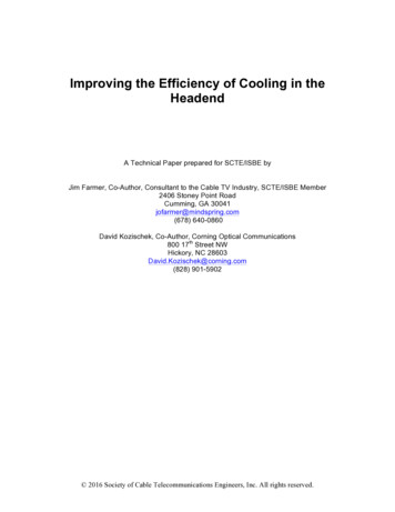
10. Variable Speed Fan Drives (general airflow issues) (Opportunity8)In this section general airflow issues are reviewed, though the referenced listing (endnote 1) refers tovariable speed fan drives. Even many home heating and air conditioning units use variable speed airhandling, because it does improve the efficiency of heating and cooling. When less cooling is needed, fanspeeds are reduced. This improves the efficacy and efficiency of cooling because it keeps the air movingat all times, improving the consistency of air temperature and reducing the losses associated with airblockages (more on this later).11.Effect of Reducing Cooling Air SpeedWe can illustrate the effect of reducing cooling air speed by referring to an analogy with electricalsystems. The volume of air passing a certain point is analogous to current in an electrical circuit. Themoving air encounters resistance from turns it must make and from obstructions it encounters, such asgrating and cables it must flow around. Finally, the pressure differential between air at the output of ablower and at the input is analogous to voltage. Thus, we have an equivalent of Ohm’s law that sayspressure (air flow)*(resistance). The power required to move the air is (power) (air flow)2*(resistance).This is the power required to move the air in a circuit consisting of the blower, the cooling apparatus, andthe air path in the headend. You can see that the power required moving the air is proportional to thesquare of the air speed. (There are some non-linear effects in air flow that can cause the resistance to be afunction of air speed, thereby exacerbating the effect described here.) Thus, the slower the airflow, theless it costs to pump it through the headend. On the other hand, the slower the air is moved, the lesseffective it is at removing heat. Hence the advantage of variable speed fan drives, which can slow downairflow when heat removal needs are lower and speed it up when required.12.Reducing the Resistance to AirflowBesides slowing the airflow when it is not required to befaster, we can reduce the resistance to airflow byeliminating or reducing as many impediments to airflow aspossible. The fewer times the air must change directions asit goes through your headend, the better. Where it enters orexits from grates, the more open the grate the lessresistance the air will encounter. Often the air handling iscombined with cable raceways, as in the air plenum ofFigure 3 above, where it is common to put the cableraceways in the plenum. This may happen in overheadenvironments too.Figure 6. Size comparison of fiber andLet’s consider options in certain wiring, to use fiber orreduced-size CAT6A bundlescopper cabling. If the air handling is shared with cabling, itwill be more efficient to use fiber, as illustrated in Figure 6,where 48 CAT6A cables are required to serve the same number of ports as is a single 0.58-inch cable 2017 Society of Cable Telecommunications Engineers, Inc. All rights reserved.11
bundle of fibers. The benefit of the smaller size of the fiber cabling is shown in Figure 6, but the savingscan also be illustrated using a simulation of airflow around the fiber and copper cabling.Figure 7. Simulation of airflow around copper and fiber cablingFigure 7 illustrates two dimensional simulations of air flow around copper and fiber interconnections. Thepressure loss is another way of expressing the resistance the air is encountering. The simulation shows apressure loss of 63 percent for the copper model and only 33 percent for the fiber model, making the pointthat the smaller the size of the cabling the less energy it is going to take to move air passed it.13.Advantages of Fiber in the HeadendFiber offers a number of advantages over copper (CAT 5/6) cabling in the headend, some of which havebeen alluded to above. The size of the fiber bundle needed to move a given amount of data is smaller thanthe size of the bundle of copper wiring needed to move the same amount of data. This smaller fiberbundle obviously impedes airflow less, as illustrated above in Figure 7. It can also make cabling theheadend easier, as both the size and weight of cabling is reduced.In many cases, multimode fiber can be used in the headend. It is not intended to transport signals longdistances, but it may work in the headend. Multimode fiber can be preferable over single-mode fiber forseveral reasons. First, connector attachment with multimode fiber is faster than connector attachment foreither single-mode fiber or for CAT 5/6 cable, with less chance for error. Another reason is that the lightis visible, making signal tracing easier and drastically reducing the potential of eye damage frominadvertently looking into an active fiber. 2017 Society of Cable Telecommunications Engineers, Inc. All rights reserved.12
As illustrated in Figure 1, fiber transceivers dissipate about one-third the power dissipated by coppertransceivers operating at the same data rate. Finally, those who have worked around CATV RFcomponents will really appreciate this last advantage, held in common with fiber optic cable in the plant:there is no possibility of RF pick-up or radiation from fiber optic interconnects, and no possibility of itintroducing ground loops.14.ConclusionsAs we strive to get more performance from inside plant, with fewer dollars allocated to get thatperformance, ultimately our attention falls on the efficacy and efficiency of the cooling in headends andhubs. The better job done in cooling, the better (and cheaper) our plant will perform. For a majorrenovation or new build, it is likely advantageous to bring in a cooling expert who can define theoptimum ways to cool, given your equipment mix and climate.15.Appendix: The Difference Between Headends and HubsviThose from a telephone background call the point where signals are assembled to go to subscribers, acentral office, or CO. Those from a cable TV background call it a headend. Either way, it is the point atwhich communications of all types are assembled for transmission to the customer.Telco people might call a field-mounted terminal which converts signal formats and sends them the lastdistance to a home a digital subscriber line access multiplexer, or DSLAM. Cable telecommunicationspeople call it a hub (maybe a node would also fit that description, we shall define both below). 2017 Society of Cable Telecommunications Engineers, Inc. All rights reserved.13
Figure 8. Headends and Hubs in Cable TV PlantFigure 8 illustrates a high-level HFC system as it might be applied in a large metropolitan area. A primaryheadend gathers most or all TV content, and may be the interface point for data and voice services. Anoptional secondary headend, which mirrors the functions of the primary headend, may be placed in ageographically different part of the metropolitan area, so that if a disaster, such as a fire, occurs at theprimary headend, the secondary headend can take over. The headend(s) are linked using fiber opticcables, to hubs, which may serve 10,000 to 20,000 customers. The hub may include certain data andmaybe voice equipment and will typically convert signals to the RF modulated format needed on thecoaxial cable. The RF signals are in turn modulated onto optical carriers in optical transmitters. Theoutput of these transmitters differs from that which you may have experience with for transmitting data.Rather than transmitting a digital signal, represented by light ON for a binary 1 and OFF for a binary 0 (orvice versa), the optical transmitter of Figure 8 is a linear (analog) transmitter capable of transmitting awide spectrum of RF signals (typically from 54 MHz to 1,002 MHz or more in North America), each RFsignal carrying one of several types of content: one 6 MHz (8 MHz in many parts of the world) channelmay carry one analog video signal (declining in use), or multiple digital TV signals, or time-divisionmultiplexed data including voice. These signals are assigned a frequency band, and many such signals cancoexist at one time on one fiber optic transmitter.The optical transmitter puts signals described above onto a fiber optic cable, which traverses most of thedistance to a neighborhood to be served. At the neighborhood, a node demodulates the optical signal,turning it back into the RF modulated carriers which went into the optical transmitter. From here, thesignals are transported to homes through coaxial cable. RF amplifiers are usually needed to overcomesignal loss, which loss may be attributed to two mechanisms. Each time a tap is used remove some signal 2017 Society of Cable Telecommunications Engineers, Inc. All rights reserved.14
power to serve one or more homes, conservation of energy dictates that less power is available to gofurther downstream to other homes. The second mechanism is loss in the coaxial cable itself, which canbe significant. If the signal level gets too low, then analog channels get noisy (“snow” in the picture). Ifdigital signals get too low in amplitude, the picture or data disappears, with just a small signal level rangewhere the picture breaks up.Upstream signals are all RF-modulated carriers, returned over the coax by using lower frequencies on thecoax (typically 5 to 42 MHz in North America). At the node they are modulated onto an optical carrier byan upstream transmitter, and then transmitted to the hub, usually on a dedicated fiber. Sometimes thesame fiber used for downstream transmission will also be used for upstream transmission, using adifferent wavelength.Many areas of the world use other transmission standards. In many locations, RF channels are 8 MHzwide rather than the 6 MHz used in North America, and carry upstream signal at frequencies up to about65 MHz, with downstream signals being carried from about 85 MHz up. For many years there has beentalk in North America about changing our split between upstream and downstream frequencies, butmomentum and the market are hard things to products/low carbon it campaign/12 ways save energy data centerBen Cutler, Spencer Fowers, Jeffrey Kramer and Eric Peterson, Want an Energy-Efficient Data Center? Build ItUnderwater, IEEE Spectrum Special Report, Feb. 21, 2017, df, Table 5.3, "Average Price of Electricity to UltimateConsumers." Use "Commercial" pdate/wholesale markets.cfm, "Electricity Monthly Update" using datafor December 2016.vChris Jaggers and Travis North, Airflow Containment: The Road to Data Center Efficiency, BICSI NewsMagazine, May/June 2010. See http://www.nxtbook.com/nxtbooks/bicsi/news 20100506/index.phpviAdapted from Farmer et. al., FTTx Networks: Technology I
Headend A Technical Paper prepared for SCTE/ISBE by Jim Farmer, Co-Author, Consultant to the Cable TV Industry, SCTE/ISBE Member 2406 Stoney Point Road Cumming, GA 30041 jofarmer@mindspring.com (678) 640-0860 David Kozischek, Co-Author, Corning Optical Communications