Transcription
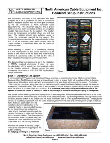
North American Cable Equipment Inc.Headend Setup InstructionsThe information contained in this document has beencompiled as a set of guidelines to install a commercialSMATV headend system that has been pre-assembledby the lab technicians at North American CableEquipment Inc. This document assumes that a propersight survey has been conducted and that an acceptablelocation has been chosen for the system. The locationshould be temperature controlled, clean, dry and dustfree. The location should have sufficient power tohandle the amperage required by the system. Thisdocument also assumes that the required satellite dishesand or off air antennas have been installed with theproper number of coaxial lines wired into the headend’sdesired location.When installing a system in a commercial building,it is the responsibility of the on-site technician to beaware of and follow all of the state and local building,electrical & grounding codes as well as the rules ofThe Federal Communications Commission (FCC).This document has been designed to aid in the installationof SMATV headend electronics, it does not coverthe distribution of the signal from the headend systemto the viewing locations. Please contact our salesengineering department at (610) 429-1726 for distributiondesign assistance.Figure 1Step 1: Unpacking The SystemA commercial SMATV system is a delicate yet heavy assembly of precision electronics. North American CableEquipment Inc. (NACE) takes great care when packing a system to ensure that it will be delivered free of damage.Systems are shipped in a wood crate with an endoskeleton that was designed to protect the system. The insideof the crate has been lined with a foam damper that is required to reject the effects of vibration during the systemsvoyage to it’s desired location. The system is also wrapped in bubble wrap and covered with shrink wrap to furtheravoid the effects of vibration, static and moisture. It is extremely important for the party taking receipt of thesystem to notify the carrier at delivery if there is any damage at all to the outside packaging of the system.The system should be left by the carrier laying flat on its attached pallet. Remove the screws from the lid of the crateand remove the lid. Remove the end and or one of the sides of the crate. By removing the foam packing material fromthe sides, top and bottom of the system, you will make room to be able to lift the system from the crate. Most systemswill take at least two people to lift from the crate. Lift the system from the crate and set the system upright on its base.Items that have been ordered for theInstallation but are not attached to theheadend may be in boxes inside the crate.Do not discard the crate and packingmaterial until you have looked through thepacking thoroughly to make sure that thereare no products hidden. Pay close attentionfor items such as flat non penetrating roofmounts that could be in the bottom of thecrate under all of the packing materials.Now that the system is standing upright,remove the outer shrink wrapping and thebubble wrapping.Do not plug anything in at this time!Figure 2North American Cable Equipment Inc. (800) 688-9282 Fax: (610) cancable.comPage 1
North American Cable Equipment Inc.Headend Setup InstructionsStep 2: Arranging The RacksIn many systems there will be more than one rack of electronics. If this is the case, line the racks in a row with thelowest channels being on the left when facing the front of the rack. Align the remaining racks with the channels inascending order from left to right. This is important since the cables that connect the racks have been cut to lengthand will not be the right length if the racks are not in order. All of the connections that will be used to interconnectthe racks are located at the top of the back of the racks on the Rack Interface Plates (RIP). Be sure to leave plenty ofroom to walk behind the racks.Do not plug anything in at this time!Step 3: Grounding The SystemIt is the responsibility of the installer to be aware of and to follow all local codes regarding grounding. Systems mustbe grounded in accordance with National Electric Code article 250. All racks must be grounded before you beginworking on them. Most importantly, they must be grounded before the coaxial satellite lines are attached and beforethe system is plugged into a live AC outlet. In systems with multiple racks 1/2” flat braid ground cable with 1/4-20 boltsworks well as long as it meets all local codes.Figure 3Step 4: Interconnecting The RacksInterconnecting the racks has been made very simple with the inclusion of a Rack Interface Plate (figure 3) located atthe top rear of each rack. The RIP is designed to conveniently locate the satellite and antenna inputs as well as theRF test outputs. For systems that require more than one rack, the rack interface plate also houses the connections forthe cables that must run between the multiple racks. All inputs/outputs have been placed on these plates and labeledso you can quickly attach all necessary cables. It is important that the system is not powered up until thecertified working satellite feeds have been connected to the system. Powering the receivers without satelliteinput could cause the receiver to begin a boot sequence that will be interrupted. This shouldn’t damage the receiverbut it will take longer to program the receiver once the satellite lines are connected.First:Locate your satellite inputs on the RIP. These will be labeled with the type of feed (DTV or DISH)followed by the voltage (18 or 13). For example, a DTV 18V signal, would be labeled as “DTV18V INPUT” on the R.I.P. In the event you have multiple lines coming in from multiple satellitepositions, the plate will be marked accordingly. Example 101 13V, 101 18V, 119 13V, 119 18V.Connect your satellite feed lines into the respective ports at this time. If the system is integratingan off-air antenna via demodulators and modulators, there will be a port on the plate labeled“ANT IN” for the antenna input.Second:Cables cut to custom lengths will be located on one of the racks. Use these cables to connect theports on the racks by matching the numbers (1 to 1, 2 to 2, 3 to 3 etc.). This will connect all of yourmultiswitches to the correct input signals, combine each racks combiner onto one line and provideyou with two open ports on the top of one of the racks. The first port will be labeled “FINAL OUTPUT”.This is the output you will use to begin your distribution. The second port will be labeled “TEST TV”.This port has been attenuated and can be used as a test port to connect a television in theheadend room.North American Cable Equipment Inc. (800) 688-9282 Fax: (610) cancable.comPage 2
North American Cable Equipment Inc.Headend Setup InstructionsStep 4: Interconnecting The Racks (Continued)Third:With a connector wrench, tighten all connectors to ensure a clean connection. Be very careful notto torque these connections too hard. Connectors are factory tightened during assembly but theycan vibrate loose in shipping. Push each of the RCA connections in to make sure they did not vibrateloose during shipping. Make sure that all of the power cords are plugged in.Fourth:Find all of the remotes in the room and remove the batteries. The accidental push of a button froma single remote can change settings on some or all of the receivers in the rack. If you need touse a remote to program the receivers, select one and make sure that it is used on one isolatedreceiver at a time. After the system is installed, hide the remote in one of the rack rails so that it is notaccidentally used. Some installers prefer to cover the remote eye of each receiver with a smallstrip of electrical tape .Fifth:Before plugging the system in, it is imperative that the outlet, wire and circuit being used have anamperage rating that is sufficient for the system being plugged in. A standard headend rack with 24receivers and 24 micro modulators would require a minimum 15 Amp circuit. An EMI, RFI ratedoutlet is recommended. For assistance in calculating the required amperage, please contact NACEbefore plugging in the system.Sixth:Locate the power cord for each rack. This will usually be located at the bottom of the rack on theback of the rack mounted, surge protected power center. Plug each rack into its designated outletbeing sure not to overload the circuit. Turn on the power centers and your system should come alive.Figure 4North American Cable Equipment Inc. (800) 688-9282 Fax: (610) cancable.comPage 3
North American Cable Equipment Inc.Headend Setup InstructionsStep 5: Setting Up The ReceiversSince the receivers are not authorized by the satellite signal provider (usually DIRECTV or DISH NETWORK) at thetime of assembly, they will not be tuned to the desired program. Each of the receivers will be labeled on the frontwith the output channel number of the modulator it is wired to at the very least. If programming information issupplied to NACE at the time of assembly, this information may be on the label as well. Consult your programmingcontract to determine what programming will be on each receiver.Step 6: Balancing The OutputDo not adjust any of the tuning screws on the modulators or amplifiers if you do not have a signal level orspectrum analyzer connected to the system.RF Output:Each system is balanced according to the customer’s requirements. If no requirements are issuedat the time of assembly, the system will be balanced with a flat 45 dBmV RF output.Aural Carriers: Aural carriers are normally set at least 16 dB below the video carriers.Audio:Volume levels are set to an even level during assembly using a constant input. When the receiversare authorized and providing individual programming to each of the modulators the volume mayneed to be adjusted to compensate for differences in the input to each modulator.Video:Video levels are balanced during assembly to provide a balanced brightness and contrast using aconstant, fixed input. This level may need to be adjusted slightly when individual programming issupplied to the modulator by its satellite receiver.Figure 5Adjusts VolumeAdjusts BrightnessOf VideoAdjusts RFOutput Level (dBmV)Adjusts Audio ToVideo Output RatioCongratulations, your system should now be ready to connect to your distribution system.North American Cable Equipment Inc. (800) 688-9282 Fax: (610) cancable.comPage 4
North American Cable Equipment Inc.Headend Setup InstructionsTroubleshootingTroubleshooting:Most of the troubles that arise during the setup of a pre-built headend system can be solved by simplyIsolating the problem.Trouble With Groups Of Channels:If you are missing a selected group of channels, find out what each of these channels have in common.Are all of the channels on one rack?If Yes, does the rack have sufficient AC power?Are all of the receivers connected to the same multiswitch?If Yes, using a satellite meter confirm that the inputs to the multiswitch have adequatesignal level.If the proper signal level is at the input to the switch, confirm that the switch has the properoutput voltages (13V/18V). Doing this will confirm that the switch is receiving power from thepower supply. If there is no LNB power out of the switch, swap the switches power supplywith a known working unit to see if this solves the problem.Are all of the channels from a specific satellite position?Confirm that the incoming lines from the satellite dish contain signal from the desired satelliteposition. If you do not have a meter that verifies the incoming satellite position, hook asatellite receiver directly to each of the incoming satellite lines.Are all of the channels from one polarity of a single satellite position?Follow the steps above to determine if the problem lies in the LNB, incoming satellite lines,satellite splitters, satellite power supply or individual multi-switch input ports.Are all of the channels on a single combiner?If Yes, check the connections to ensure that the output cable from the combiner is connectedto the output of the combiner and the combining network (usually a splitter/combiner) usedto combine multiple combiners together before going into the system amplifier.Are the modulators plugged into the same power supply?If Yes, swap the power supply in question with a known working unit and see if this fixesthe problem.North American Cable Equipment Inc. (800) 688-9282 Fax: (610) cancable.comPage 5
North American Cable Equipment Inc.Headend Setup InstructionsTrouble With An Individual Channel:If you are having trouble with a single channel’s audio, video or audio and video the problem canusually be isolated to either the receiver or the modulator.Receiver Isolation Test:If you have no audio or video on channel 9, plug the audio (red) and video (yellow) lines from the inputof the channel 9 modulator into the channel 10 (known working) modulator. If you now get no pictureon channel 10 you are likely to have either have a bad receiver or bad cables. If you have determinedthat the receiver is not working properly, skip to the receiver troubleshooting section below.Modulator Isolation Test:If this does not fix the problem, try connecting the audio and video input lines from the channel 10(known working) modulator into the channel 9 modulator. If you get no picture on channel 9, themodulator is likely to be the problem. If you have determined that the modulator is not workingproperly, contact our lab for further troubleshooting options at (610) 429-1726.In From MultiswitchGray RG-6Figure 6 Receiver ConnectionsVideo Out To ModulatorYellow RG-59,RCA ConnectorAudio Out To ModulatorRed RG-59,RCA ConnectorVideo In From ReceiverYellow RG-59,F ConnectorFigure 7 Modulator ConnectionsAudio In From ReceiverRed RG-59,RCA ConnectorRF Out To CombinerGreen RG-59,F ConnectorReceiver Troubleshooting:If you are having a problem with particular channel and you have isolated the problem to the satellite receiver, seethe following two pages for detailed receiver troubleshooting.To download current receiver software on a DIRECTV D11 receiver, follow the steps below.To verify the current software version:MENUAs of 6/29/06, the current software version is 0X1005.Follow these steps to force a receiver to update software.1. Reset the receiver.2. While it is re-booting, press 02468 on the remote.3. The on-screen display will confirm a download in progress.North American Cable Equipment Inc. (800) 688-9282 Fax: (610) cancable.comPage 6
North American Cable Equipment Inc. (800) 688-9282 Fax: (610) 429-3060 sales@northamericancable.com www.northamericancable.com Page 2 North American Cable Equipment Inc. Headend Setup Instructions Step 2: Arranging The Racks In many systems there will be more than one rack of electronics. If this is the case, line the racks in a row with the