Transcription
SATA Product ManualStandard 512E modelST8000NE001ST6000NE000ST4000NE001100844774, Rev. HGen. 10 March 2021
Document Revision HistoryRevisionDatePages affected and Description of changesRev. A11/29/2018Initial release.Rev. B04/22/2019fc, 5, 7 & 9: Removed 4TB model - ST4000NE0007: Update 6TB heads & disks7 & 27: Updated weights8 & 18: Updated Non-op shock to 300 Gs for all capacities8 & 20: Added (command controlled) to L/ULbc: Removed APAC & EMEA addressesRev. C05/09/2019fc, 5, 7, 9, 11, 13, 25-26 & 31: Removed 2TB model16: Updated Shock & Vibration sectionRev. D08/21/20197, 15 & 18: Updated or verified text reflects: drive reported temperaturesRev. E09/10/2019fc & 24-25: Added SRS contentRev. F01/07/20207: Updated temperature & humidity gradients7 & 13: Updated 5V tolerance to 5%27-28: Updated Figure 4 title & added Figure 5.Rev. G03/04/202019: Section 2.12 - Removed HDD and SSD Regulatory Compliance and Safety reference24: Updated Figure 4 Mounting configuration dimensions 8TB models (Option 1)Rev. H03/12/20217-8 &15: Revised operating temperature range statements & notes7 & 9: Updated Sustained Data Rates19: Updated Section 2.12 HDD and SSD Regulatory Compliance and Safety 2021 Seagate Technology LLC. All rights reserved.Publication number: 100844774, Rev. H March 2021Seagate, Seagate Technology and the Spiral logo are registered trademarks of Seagate Technology LLC in the United States and/or other countries. PowerChoice and SeaTools are eithertrademarks or registered trademarks of Seagate Technology LLC or one of its affiliated companies in the United States and/or other countries. The FIPS logo is a certification mark of NIST,which does not imply product endorsement by NIST, the U.S., or Canadian governments. All other trademarks or registered trademarks are the property of their respective owners.No part of this publication may be reproduced in any form without written permission of Seagate Technology LLC.Call 877-PUB-TEK1 (877-782-8351) to request permission.When referring to drive capacity, one gigabyte, or GB, equals one billion bytes and one terabyte, or TB, equals one trillion bytes. Your computer’s operating system may use a differentstandard of measurement and report a lower capacity. In addition, some of the listed capacity is used for formatting and other functions, and thus will not be available for data storage.Actual quantities will vary based on various factors, including file size, file format, features and application software. Actual data rates may vary depending on operating environmentand other factors. The export or re-export of hardware or software containing encryption may be regulated by the U.S. Department of Commerce, Bureau of Industry and Security (formore information, visit www.bis.doc.gov), and controlled for import and use outside of the U.S. Seagate reserves the right to change, without notice, product offerings or specifications.
ContentsSeagate Technology Support Services . . . . . . . . . . . . . . . . . . . . . . . . . . . . . . . . . . . . . . . . . . . . . . . . . . . . . . . . . . . . . . . 41.0Introduction . . . . . . . . . . . . . . . . . . . . . . . . . . . . . . . . . . . . . . . . . . . . . . . . . . . . . . . . . . . . . . . . . . . . . . . . . . . . . . . . . 51.1About the Serial ATA interface . . . . . . . . . . . . . . . . . . . . . . . . . . . . . . . . . . . . . . . . . . . . . . . . . . . . . . . . . . . . . . . . 62.0Drive specifications . . . . . . . . . . . . . . . . . . . . . . . . . . . . . . . . . . . . . . . . . . . . . . . . . . . . . . . . . . . . . . . . . . . . . . . . . . 72.1Specification summary tables . . . . . . . . . . . . . . . . . . . . . . . . . . . . . . . . . . . . . . . . . . . . . . . . . . . . . . . . . . . . . . . . . 72.2Formatted capacity . . . . . . . . . . . . . . . . . . . . . . . . . . . . . . . . . . . . . . . . . . . . . . . . . . . . . . . . . . . . . . . . . . . . . . . . . . 92.2.1LBA mode. . . . . . . . . . . . . . . . . . . . . . . . . . . . . . . . . . . . . . . . . . . . . . . . . . . . . . . . . . . . . . . . . . . . . . . . . . 92.3Recording and interface technology . . . . . . . . . . . . . . . . . . . . . . . . . . . . . . . . . . . . . . . . . . . . . . . . . . . . . . . . . . 92.4Start/stop times . . . . . . . . . . . . . . . . . . . . . . . . . . . . . . . . . . . . . . . . . . . . . . . . . . . . . . . . . . . . . . . . . . . . . . . . . . . . . . 92.5Power specifications . . . . . . . . . . . . . . . . . . . . . . . . . . . . . . . . . . . . . . . . . . . . . . . . . . . . . . . . . . . . . . . . . . . . . . . . . 102.5.1Power consumption . . . . . . . . . . . . . . . . . . . . . . . . . . . . . . . . . . . . . . . . . . . . . . . . . . . . . . . . . . . . . . . 102.5.2Conducted noise . . . . . . . . . . . . . . . . . . . . . . . . . . . . . . . . . . . . . . . . . . . . . . . . . . . . . . . . . . . . . . . . . . 132.5.3Voltage tolerance . . . . . . . . . . . . . . . . . . . . . . . . . . . . . . . . . . . . . . . . . . . . . . . . . . . . . . . . . . . . . . . . . 132.5.4Extended Power Conditions - PowerChoice . . . . . . . . . . . . . . . . . . . . . . . . . . . . . . . . . . . . . . . 132.6Environmental limits. . . . . . . . . . . . . . . . . . . . . . . . . . . . . . . . . . . . . . . . . . . . . . . . . . . . . . . . . . . . . . . . . . . . . . . . . 152.6.1Temperature . . . . . . . . . . . . . . . . . . . . . . . . . . . . . . . . . . . . . . . . . . . . . . . . . . . . . . . . . . . . . . . . . . . . . . 152.6.2Humidity. . . . . . . . . . . . . . . . . . . . . . . . . . . . . . . . . . . . . . . . . . . . . . . . . . . . . . . . . . . . . . . . . . . . . . . . . . 162.6.3Effective Altitude (sea level) . . . . . . . . . . . . . . . . . . . . . . . . . . . . . . . . . . . . . . . . . . . . . . . . . . . . . . . 162.7Shock and Vibration . . . . . . . . . . . . . . . . . . . . . . . . . . . . . . . . . . . . . . . . . . . . . . . . . . . . . . . . . . . . . . . . . . . . . . . . . 162.7.1Shock . . . . . . . . . . . . . . . . . . . . . . . . . . . . . . . . . . . . . . . . . . . . . . . . . . . . . . . . . . . . . . . . . . . . . . . . . . . . . 162.7.2Vibration. . . . . . . . . . . . . . . . . . . . . . . . . . . . . . . . . . . . . . . . . . . . . . . . . . . . . . . . . . . . . . . . . . . . . . . . . . 162.8Acoustics. . . . . . . . . . . . . . . . . . . . . . . . . . . . . . . . . . . . . . . . . . . . . . . . . . . . . . . . . . . . . . . . . . . . . . . . . . . . . . . . . . . . 172.9Test for Prominent Discrete Tones (PDTs) . . . . . . . . . . . . . . . . . . . . . . . . . . . . . . . . . . . . . . . . . . . . . . . . . . . . . 172.10Electromagnetic immunity. . . . . . . . . . . . . . . . . . . . . . . . . . . . . . . . . . . . . . . . . . . . . . . . . . . . . . . . . . . . . . . . . . . 172.11Reliability . . . . . . . . . . . . . . . . . . . . . . . . . . . . . . . . . . . . . . . . . . . . . . . . . . . . . . . . . . . . . . . . . . . . . . . . . . . . . . . . . . . 182.11.1Annualized Failure Rate (AFR) and Mean Time Between Failures (MTBF) . . . . . . . . . . . . . 182.12HDD and SSD Regulatory Compliance and Safety . . . . . . . . . . . . . . . . . . . . . . . . . . . . . . . . . . . . . . . . . . . . . 192.12.1Safety certification . . . . . . . . . . . . . . . . . . . . . . . . . . . . . . . . . . . . . . . . . . . . . . . . . . . . . . . . . . . . . . . . 192.12.2Regulatory Models . . . . . . . . . . . . . . . . . . . . . . . . . . . . . . . . . . . . . . . . . . . . . . . . . . . . . . . . . . . . . . . . 192.13Corrosive environment . . . . . . . . . . . . . . . . . . . . . . . . . . . . . . . . . . . . . . . . . . . . . . . . . . . . . . . . . . . . . . . . . . . . . . 192.14Reference documents . . . . . . . . . . . . . . . . . . . . . . . . . . . . . . . . . . . . . . . . . . . . . . . . . . . . . . . . . . . . . . . . . . . . . . . 202.15Product warranty . . . . . . . . . . . . . . . . . . . . . . . . . . . . . . . . . . . . . . . . . . . . . . . . . . . . . . . . . . . . . . . . . . . . . . . . . . . . 202.16Seagate Rescue Data Recovery Service . . . . . . . . . . . . . . . . . . . . . . . . . . . . . . . . . . . . . . . . . . . . . . . . . . . . . 21Seagate IronWolf Pro SATA Product Manual, Rev. H2
Contents3.0Configuring and mounting the drive . . . . . . . . . . . . . . . . . . . . . . . . . . . . . . . . . . . . . . . . . . . . . . . . . . . . . . . . . 233.1Handling and static-discharge precautions . . . . . . . . . . . . . . . . . . . . . . . . . . . . . . . . . . . . . . . . . . . . . . . . . . . 233.2Configuring the drive . . . . . . . . . . . . . . . . . . . . . . . . . . . . . . . . . . . . . . . . . . . . . . . . . . . . . . . . . . . . . . . . . . . . . . . . 233.3Serial ATA cables and connectors . . . . . . . . . . . . . . . . . . . . . . . . . . . . . . . . . . . . . . . . . . . . . . . . . . . . . . . . . . . . 233.4Drive mounting . . . . . . . . . . . . . . . . . . . . . . . . . . . . . . . . . . . . . . . . . . . . . . . . . . . . . . . . . . . . . . . . . . . . . . . . . . . . . 233.4.1Mechanical specifications . . . . . . . . . . . . . . . . . . . . . . . . . . . . . . . . . . . . . . . . . . . . . . . . . . . . . . . . . 244.0Serial ATA (SATA) interface . . . . . . . . . . . . . . . . . . . . . . . . . . . . . . . . . . . . . . . . . . . . . . . . . . . . . . . . . . . . . . . . . . 264.1Hot-Plug compatibility. . . . . . . . . . . . . . . . . . . . . . . . . . . . . . . . . . . . . . . . . . . . . . . . . . . . . . . . . . . . . . . . . . . . . . . 264.2Serial ATA device plug connector pin definitions . . . . . . . . . . . . . . . . . . . . . . . . . . . . . . . . . . . . . . . . . . . . . 264.3Supported ATA commands . . . . . . . . . . . . . . . . . . . . . . . . . . . . . . . . . . . . . . . . . . . . . . . . . . . . . . . . . . . . . . . . . . 274.3.1Identify Device command . . . . . . . . . . . . . . . . . . . . . . . . . . . . . . . . . . . . . . . . . . . . . . . . . . . . . . . . . 294.3.2Set Features command . . . . . . . . . . . . . . . . . . . . . . . . . . . . . . . . . . . . . . . . . . . . . . . . . . . . . . . . . . . . 324.3.3S.M.A.R.T. commands. . . . . . . . . . . . . . . . . . . . . . . . . . . . . . . . . . . . . . . . . . . . . . . . . . . . . . . . . . . . . . 33Seagate IronWolf Pro SATA Product Manual, Rev. H3
Seagate Technology Support ServicesFor Seagate Product Support, visit: www.seagate.com/supportFor Seagate Compliance, Safety, and Disposal, visit: www.seagate.com/supportFor Firmware Download and Tools Download for Secure Erase, visit: www.seagate.com/support/downloads/For information regarding online support and services, visit: /www.seagate.com/contacts/For information regarding Warranty Support, visit: For information regarding data recovery services, visit: www.seagate.com/services-software/recover/For Seagate OEM and Distribution partner and Seagate reseller portal, visit: www.seagate.com/partnersSeagate IronWolf Pro SATA Product Manual, Rev. H4
1.0IntroductionThis manual describes the functional, mechanical and interface specifications for the following:Seagate IronWolf Pro Serial ATA model drives:5xxE Standard modelsST8000NE001ST4000NE001ST6000NE000These drives provide the following key features: 7200 RPM spindle speed. Full-track multiple-sector transfer capability without local processor intervention. High instantaneous (burst) data-transfer rates (up to 600MB per second). Native Command Queuing with command ordering to increase performance in demanding applications. Perpendicular recording technology provides the drives with increased areal density. PowerChoice for selectable power savings SeaTools diagnostic software performs a drive self-test that eliminates unnecessary drive returns. State-of-the-art cache and on-the-fly error-correction algorithms. Support for S.M.A.R.T. drive monitoring and reporting. Supports latching SATA cables and connectors. Tarnish-resistant components to help protect drive from environmental elements, increasing field reliability. Worldwide Name (WWN) capability uniquely identifies the drive.NoteSeagate recommends validating the configuration with the selected HBA/RAID controller manufacturer to ensure use of full capacity is supported.Seagate IronWolf Pro SATA Product Manual, Rev. H5
1.1About the Serial ATA interfaceThe Serial ATA interface provides several advantages over the traditional (parallel) ATA interface. The primary advantages include: Easy installation and configuration with true plug-and-play connectivity.It is not necessary to set any jumpers or other configuration options. Thinner and more flexible cabling for improved enclosure airflow and ease of installation. Scalability to higher performance levels.In addition, Serial ATA makes the transition from parallel ATA easy by providing legacy software support. Serial ATA was designed toallow users to install a Serial ATA host adapter and Serial ATA disk drive in the current system and expect all of the existingapplications to work as normal.The Serial ATA interface connects each disk drive in a point-to-point configuration with the Serial ATA host adapter. There is nomaster/slave relationship with Serial ATA devices like there is with parallel ATA. If two drives are attached on one Serial ATA hostadapter, the host operating system views the two devices as if they were both “masters” on two separate ports. This essentiallymeans both drives behave as if they are Device 0 (master) devices.NoteThe host adapter may, optionally, emulate a master/slave environment to host software where twodevices on separate Serial ATA ports are represented to host software as a Device 0 (master) andDevice 1 (slave) accessed at the same set of host bus addresses. A host adapter that emulates a master/slave environment manages two sets of shadow registers. This is not a typical Serial ATA environment.The Serial ATA host adapter and drive share the function of emulating parallel ATA device behavior to provide backwardcompatibility with existing host systems and software. The Command and Control Block registers, PIO and DMA data transfers, resets,and interrupts are all emulated.The Serial ATA host adapter contains a set of registers that shadow the contents of the traditional device registers, referred to as theShadow Register Block. All Serial ATA devices behave like Device 0 devices. For additional information about how Serial ATA emulatesparallel ATA, refer to the “Serial ATA: High Speed Serialized AT Attachment” specification. The specification can be downloaded fromwww.serialata.org.Seagate IronWolf Pro SATA Product Manual, Rev. H6
2.0Drive specificationsUnless otherwise noted, all specifications are measured under ambient conditions, at 25 C, and nominal power. For convenience, thephrases the drive and this drive are used throughout this manual to indicate the following drive models:5xxE Standard ation summary tablesThe specifications listed in the following tables are for quick reference. For details on specification measurement or definition, see theappropriate section of this manual.Table 1 Drive specifications summaryDrive specificationFormatted (512 6TB4TB(see Section 2.2)Guaranteed sectorsHeads10106Discs553Bytes per logical sector512Bytes per physical sector4096Recording density, KBPI (Kb/in max)2509Track density, KTPI (ktracks/in, 0 skew)371Areal density, (Gb/in2, @ 0 skew mid-disk)930Spindle speed (RPM)7200Internal data transfer rate (Mb/s max)2850Sustained data transfer rate OD (MiB/s max)229 (240MB/s max)210 (220MB/s max)600I/O data-transfer rate (MB/s max)ATA data-transfer modes supportedCache bufferWeight: (maximum)PIO modes 0–4Multiword DMA modes 0–2Ultra DMA modes 0–6256MB (262,144KB)716g (1.557 lb)649g (1.431 lb)Average latency4.16msPower-on to ready (sec) (typ/max)23/30Standby to ready (sec) (typ/max)23/30Startup current (typical) 12V (peak)2.0AVoltage tolerance (including noise)5V 5%12V 10%Operating ambient temperature (min C)*Operating temperature (max C)*Non-Operating temperatureTemperature gradient ( C per hour max)Relative humidity*Relative humidity gradientSeagate IronWolf Pro SATA Product Manual, Rev. H0 C (Ambient)65 C (Drive Reported Temperature) †–40 to 70 C (Ambient Temperature, see sections 2.6.1 and 2.11)20 C (operating)20 C (nonoperating)5% to 95% (operating)5% to 95% (nonoperating)20% per hour max7
ST8000NE001Drive specificationST6000NE000Altitude, operating–304.8 m to 3,048 m(–1000 ft to 10,000 ft)Altitude, nonoperating(below mean sea level, max)–304.8 m to 12,192 m(–1000 ft to 40,000 ft)Operational Shock (max at 2 ms - typical)ST4000NE001Read 70 Gs / Write 40 GsNon-Operational Shock (max at 2 ms - typical)300 Gs5–22 Hz:Vibration, operating0.25 Gs, Limited displacement22–350 Hz: 0.50 Gs350–500 Hz: 0.25 GsOperation Rotational vibration20–1500Hz: 12.5 rads/s²Vibration, nonoperating10–500 Hz: 5.0 Grms refDrive acoustics, sound power (bels)2.8 (typical)3.0 (max)During periods of drive idle, some offline activity may occur according to theSMART specification, which may increase acoustic and power to operational levels.Idle3.2 (typical)3.4 (max)Performance seekNonrecoverable read errors1 sector per 1015 bits readAnnualized Failure Rate (AFR)*0.73% based on 8760 POHMaximum Rated Workload*Maximum rate of 300TB/yearWorkloads exceeding the annualized rate may degrade the drive MTBF and impact productreliability. The Annualized Workload Rate is in units of TB per year, or TB per 8760 power onhours. Workload Rate TB transferred * (8760 / recorded power on hours).WarrantyTo determine the warranty for a specific drive, use a web browser to access the following webpage: .From this page, click on the “Is my Drive under Warranty” link. The following are required tobe provided: the drive serial number, model number (or part number) and country ofpurchase.The system will display the warranty information for the drive.Load-unload cycles (command controlled)Supports Hotplug operation perSerial ATA Revision 3.3 specification#600,000YesOne GB equals one billion bytes when referring to hard drive capacity.Accessible capacity may vary depending on operating environment and formatting.* See Section 2.11, "Reliability" for rated MTBF device operating condition requirements.† Seagate does not recommend operating at sustained drive temperatures above 60 C.Operating at higher temperatures may affect drive health.Seagate IronWolf Pro SATA Product Manual, Rev. H8
2.2Formatted capacityST modelsFormatted capacity*Guaranteed 1,721,045,168ST4000NE0014TB7,814,037,168Bytes per logical sector512* One GB equals one billion bytes when referring to hard drive capacity. Accessible capacity may vary depending on operating environment and formatting.2.2.1LBA modeWhen addressing these drives in LBA mode, all blocks (sectors) are consecutively numbered from 0 to n–1, where n is the number ofguaranteed sectors as defined above.See Section 4.3.1, "Identify Device command" (words 60-61 and 100-103) for additional information about 48-bit addressingsupport of drives with capacities over 137GB.2.3Recording and interface technology8TB, 6TB & 4TBInterfaceSerial ATA (SATA)Recording methodPerpendicularRecording density, KBPI (Kb/in max)2509Track density, KTPI (ktracks/in, 0 Skew)371Areal density (Gb/in2, @ 0 skew mid-disk)930Spindle speed (RPM) ( 0.2%)7200Internal data transfer rate (Mb/s max)2850Sustained data transfer rate (MiB/s max) (8TB models)229 (240 MB/s max)Sustained data transfer rate (MiB/s max) (6TB & 4TB models210 (220 MB/s max)I/O data-transfer rate (MB/s max)600 (Ultra DMA mode 5)2.4Start/stop timesPower-on to Ready (sec) (typ/max)23/30Standby to Ready (sec) (typ/max)23/30Ready to spindle stop (sec) (max)23Seagate IronWolf Pro SATA Product Manual, Rev. H9
2.5Power specificationsThe drive receives DC power ( 5V or 12V) through a native SATA power connector. See Figure 4 on page 23.2.5.1Power consumptionPower requirements for the drives are listed in Table 2 through Table 3. Typical power measurements are based on an average ofdrives tested, under nominal conditions, using 5.0V and 12.0V input voltage at 25 C ambient temperature.Table 2DC power requirements (8TB & 6TB)6.0Gb modeVoltage 5VRegulationAvg Idle Current * 12V 5%WattsTotal0.2270.4977.06Idle A0.2260.4977.06Idle B0.1730.4265.90Idle C0.1660.2263.53Standby0.1580.010.86DC (peak DC)0.7021.6523.34AC (Peak DC)0.9681.96Advanced Idle Current *Maximum Start CurrentOperating current (random read 4K16Q)Typical DC0.3930.705Maximum DC0.3960.717Maximum DC (peak)0.112.2510.36Operating current (random write 4K16Q)Typical DC0.270.798Maximum DC0.270.805Maximum DC (peak)0.6362.2410.86Operating current (sequential read 64K16Q)Typical DC0.6960.544Maximum DC0.7010.546Maximum DC (peak)1.231.829.94Operating current (sequential write 64K16Q)Typical DC0.5930.539Maximum DC0.5930.539Maximum DC (peak)0.7040.853Seagate IronWolf Pro SATA Product Manual, Rev. H9.3710
Table 3DC power requirements (4TB)6.0Gb modeVoltage 5VRegulationAvg Idle Current * 12V 5%WattsTotal0.2370.3565.43Idle A0.2380.365.48Idle B0.1850.3044.56Idle C0.1790.0831.89Standby0.170.010.98DC (peak DC)0.7021.6523.34AC (Peak DC)0.9681.96Typical DC0.3930.705Maximum DC0.3960.717Maximum DC (peak)0.112.25Typical DC0.270.798Maximum DC0.270.805Maximum DC (peak)0.6362.24Typical DC0.6960.544Maximum DC0.7010.546Maximum DC (peak)1.231.82Typical DC0.5930.539Maximum DC0.5930.539Maximum DC (peak)0.7040.853Advanced Idle Current *Maximum Start CurrentOperating current (random read 4K16Q)10.36Operating current (random write 4K16Q)10.86Operating current (sequential read 64K16Q)9.94Operating current (sequential write 64K16Q)9.37*During periods of drive idle, some offline activity may occur according to the S.M.A.R.T. specification, which may increase acoustic and power to operational levels.Seagate IronWolf Pro SATA Product Manual, Rev. H11
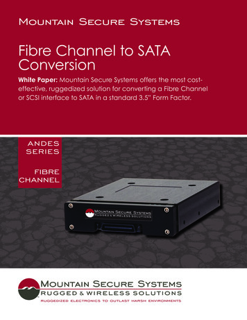
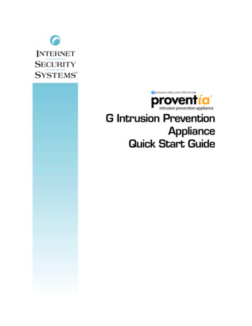
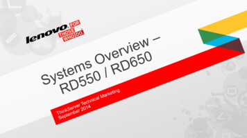
2.5.1.1Typical current profilesFigure 1.8TB & 6TB Typical 12V startup and operation current profileFigure 2.4TB Typical 12V startup and operation current profileSeagate IronWolf Pro SATA Product Manual, Rev. H12
2.5.2Conducted noiseInput noise ripple is measured at the host system power supply across an equivalent 80-ohm resistive load on the 12 V line or anequivalent 15-ohm resistive load on the 5V line. Using 12V power, the drive is expected to operate with a maximum of 120mV peak-to-peak square-wave injected noise at up to10MHz. Using 5V power, the drive is expected to operate with a maximum of 100mV peak-to-peak square-wave injected noise at up to10MHz.Equivalent resistance is calculated by dividing the nominal voltage by the typical RMS read/write current.Note2.5.3Voltage toleranceVoltage tolerance (including noise):5V 5%2.5.412V 10%Extended Power Conditions - PowerChoice Utilizing the load/unload architecture a programmable power management interface is provided to tailor systems for reducedpower consumption and performance requirements.The table below lists the supported power conditions available in PowerChoice. Power conditions are ordered from highest powerconsumption (and shortest recovery time) to lowest power consumption (and longest recovery time) as follows: Idle a power Idle b power Idle c power Standby z power. The further users go down in the table, the more power savings is actualized. Forexample, Idle b results in greater power savings than the Idle a power condition. Standby results in the greatest power savings.Power Condition NamePower Condition IDDescriptionIdle a81HReduced electronicsIdle b82HHeads unloaded. Disks spinning at full RPMIdle c83HHeads unloaded. Disks spinning at reduced RPMStandby z00HHeads unloaded. Motor stopped (disks not spinning)Each power condition has a set of current, saved and default settings. Default settings are not modifiable. Default and saved settingspersist across power-on resets. The current settings do not persist across power-on resets. At the time of manufacture, the default,saved and current settings are in the Power Conditions log match.PowerChoice is invoked using one of two methods Automatic power transitions which are triggered by expiration of individual power condition timers. These timer values may becustomized and enabled using the Extended Power Conditions (EPC) feature set using the standardized Set Features commandinterface. Immediate host commanded power transitions may be initiated using an EPC Set Features "Go to Power Condition" subcommandto enter any supported power condition. Legacy power commands Standby Immediate and Idle Immediate also provide amethod to directly transition the drive into supported power conditions.PowerChoice exits power saving states under the following conditions Any command which requires the drive to enter the PM0: Active state (media access) Power on resetSeagate IronWolf Pro SATA Product Manual, Rev. H13
PowerChoice provides the following reporting methods for tracking purposesCheck Power Mode Command Reports the current power state of the driveIdentify Device Command EPC Feature set supported flag EPC Feature enabled flag is set if at least one Idle power condition timer is enabledPower Condition Log reports the following for each power condition Nominal recovery time from the power condition to active If the power condition is Supported, Changeable, and Savable Default enabled state, and timer value Saved enabled state, and timer value Current enabled state, and timer valueS.M.A.R.T. Read Data Reports Attribute 192 - Emergency Retract Count Attribute 193 - Load/Unload Cycle CountPowerChoice Manufacture Default Power Condition Timer ValuesDefault power condition timer values have been established to assure product reliability and data integrity. A minimum timer valuethreshold of two minutes ensures the appropriate amount of background drive maintenance activities occur. Attempting to set atimer values less than the specified minimum timer value threshold will result in an aborted EPC "Set Power Condition Timer"subcommand.Power Condition NameManufacturer Default Timer ValuesIdle a100 msecIdle b2 minIdle c4 minStandby z15 minSetting power condition timer values less than the manufacturer specified defaults or issuing the EPC "Go to Power Condition"subcommand at a rate exceeding the default timers may limit this products reliability and data integrity.PowerChoice Supported Extended Power Condition Feature SubcommandsEPC SubcommandDescription00HRestore Power Condition Settings01HGo to Power Condition02HSet Power Condition Timer03HSet Power Condition State04HEnable EPC Feature Set05HDisable EPC Feature SetSeagate IronWolf Pro SATA Product Manual, Rev. H14
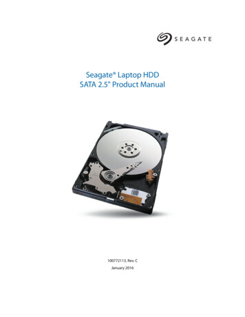
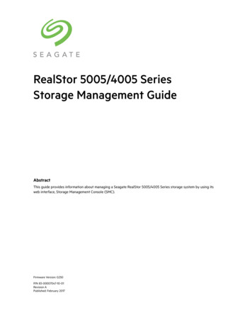
PowerChoice Supported Extended Power Condition IdentifiersPower Condition IdentifiersPower Condition Name00HStandby z01 - 80HReserved81HIdle a82HIdle b83HIdle c84 - FEHReservedFFHAll EPC Power Conditions2.6Environmental limitsTemperature and humidity values experienced by the drive must be such that condensation does not occur on any drive part.Altitude and atmospheric pressure specifications are referenced to a standard day at 58.7 F (14.8 C).To maintain optimal performance drives should be run at nominal drive temperatures and humidity.Seagate does not recommend operating at sustained drive temperatures above 60 C.Operating at higher temperatures may affect drive health.CautionSee Section 2.11, "Reliability" for rated MTBF device operating condition requirements.2.6.1Temperaturea. Operating32 F to 149 F (0 C ambient to 65 C drive reported) temperature range with a maximum temperature gradient of 36 F (20 C) perhour.The maximum allowable drive reported temperature is 149 F (65 C).Air flow may be required to achieve consistent nominal drive temperature values (see Section 3.4). To confirm that therequired cooling is provided for the electronics and HDA, place the drive in its final mechanical configuration, and performrandom write/read operations. After the temperatures stabilize, monitor the current drive temperature using the SMARTtemperature attribute 194 or Device Statistics log 04h page 5.b. Non-operating–40 to 158 F (–40 to 70 C) package ambient with a maximum gradient of 36 F (20 C) per hour. This specification assumes thatthe drive is packaged in the shipping container designed by Seagate for use with drive.HDATemperatureCheck PointFigure 3.NoteLocation of the HDA temperature check pointImage is for reference only, may not represent actual driveSeagate IronWolf Pro SATA Product Manual, Rev. H15
2.6.2HumidityThe values below assume that no condensation on the drive occurs. Maximum wet bulb temperature is 84.2 F (29 C).2.6.2.1Relative humidityOperating:5% to 95% non-condensing relative humidity with a maximum gradient of 20% per hour.Non-operating:5% to 95% non-condensing relative humidity with a maximum gradient of 20% per hour.2.6.3Effective Altitude (sea level)Operating:–304.8 m to 3048 m (–1000 ft. to 10,000 ft.)Non-operating:–304.8 m to 12,192 m (–1000 ft. to 40,000 ft.)2.7Shock and VibrationShock and vibration measurements specified in this document are made directly on the drive itself and applied in the X, Y, and Z axis at the drivemounting point locations.2.7.1Shocka. OperatingThe drive will operate without error while subjected to intermittent shock pulses not exceeding 70 Gs (read) and 40 Gs (write) at amaximum duration of 2ms.b. Non-operatingThe drive will operate without non-recoverable errors after being subjected to shock pulses not exceeding 300g at a maximumduration of 2ms.2.7.2Vibrationa. Linear Random Operating VibrationThe drive will operate without non-recoverable errors while being subjected to th
Seagate IronWolf Pro SATA Product Manual, Rev. H 6 1.1 About the Serial ATA interface The Serial ATA interface provides several advantages over the traditional (parallel) ATA interface.