Transcription
JABIRU AIRCRAFT PTY LTDP.O. Box 5186Bundaberg WestQueensland, Australia.Phone:Fax:Email:SERVICE BULLETIN:JSB 016-1Issue:1Date:19th April 2007Subject:J160 Family Engine Cooling1 61 7 4155 1778 61 7 4155 2669info@jabiru.net.auTable of Contents1TABLE OF CONTENTS .12APPLICABILITY.13BACKGROUND .14RECOMMENDATIONS: .24.14.24.34.44.54.6GENERAL .2LEVEL 1 – NO MANDATORY CHANGE .3LEVEL 1 – SMALL COWL LIP .3LEVEL 2 – MEDIUM COWL LIP .4LEVEL 3 – LARGE COWL LIP .5ONGOING MONITORING .65AIRCRAFT CONDITION NOTES .66COMPLIANCE – IMPLEMENTATION: .67AIRWORTHINESS NOTE: .72ApplicabilityAll Jabiru J160 family aircraft (All J160 & J170 models)Note that for aircraft in the LSA category, this document is equivalent to a Manufacturer’s SafetyDirection.3BackgroundWhile the engine cooling capacity of the J160 family meets design requirements, recentoperational experience has shown that in unusual conditions – such as very high ambienttemperatures or during extended ground running – the airflow over the engine is insufficient toprevent cylinder head temperatures reaching yellow or red-arc levels. Repeated operations atthese temperatures greatly increase the potential for engine overheating & subsequent damage.The following bulletin describes several levels of modification to the lower cowl which improveairflow and engine cooling – particularly on the ground & during low speed flight.
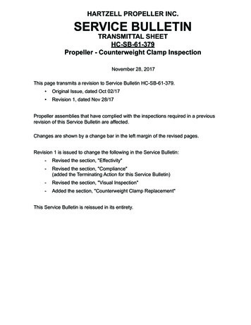
Jabiru Service Bulletin: J160 Family Engine Cooling19th April 2007JSB 016-14Recommendations:4.1GeneralThe following table has been designed to allow the engine cooling to be judged more accuratelyby operators. It contains a list of “Risk Criteria” which are known indicators of how well theengine is being cooled. The operator then assesses how often these factors are apparent intheir aircraft & adds up the totals. Note that the temperature assessments (CHT & Oil Temp inclimb) must be made after the engine has been broken in and is no longer using run-in oil.Example: An aircraft does not overheat it’s CHT or oil in a climb of 2000’, is used for flighttraining with taxi times occasionally above 10 minutes. Lower head bolts sometimes need morethan 1/8th of a turn & once had a leak on cylinder head #3. The aircraft also has a lower cowlwith the NACA oil cooler inlet (tick either the “sometimes” or “never” column for this entry).Example entries are shown in grey italics below:Table 1 – Risk AssessmentRisk CriteriaScore NeverScale Value 1CHT reaches yellow-line values in climbs of2000’ – including en-route climbs. Oil temperature reaches yellow-line values inclimbs of 2000’ – including en-route climbs. SometimesScale Value 2FrequentlyScale Value 3 Aircraft is used for flight trainingTaxi Times exceed 10 minutes The lower head bolt (between intake & exhaustports) of one or more heads need 1/8th of a turnor more to restore proper tension at service Cylinder to Cylinder head seal failed (burnt oilvisible on rear face of lower cylinder head fins –See Figure 1). Aircraft currently has lower cowl with NACAstyle oil cooler inlet. Basic totalScaled total Basic Total x Scale ValueFinal Total Sum of Scaled Totals22134813Final total value from 7 to 8 Low risk. Refer to Section 4.2Final total value from 9 to 11 low-medium risk. Refer to Section 4.3Final total value from 12 to 17 Medium risk. Refer to Section 4.4Final total value from 18 to 20 High risk. Refer to Section 4.5.JSB016-1.docPage 2 of 7
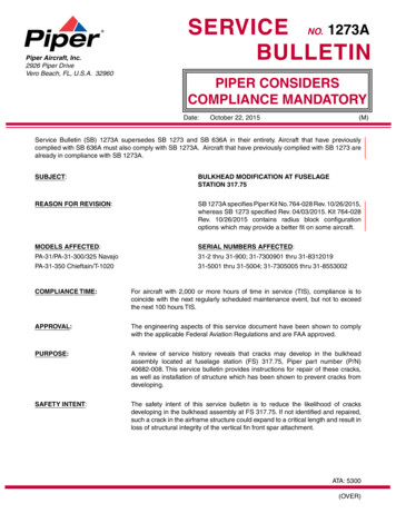
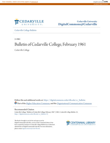
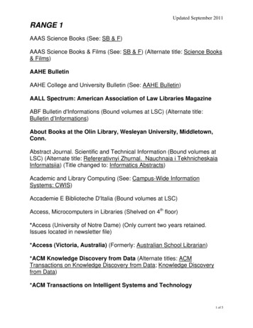
Jabiru Service Bulletin: J160 Family Engine Cooling19th April 2007JSB 016-1Inside of combustionchamber (Head shownremoved from engineLowest head bolthole & pushrod tubecut-outsBurnt oil stainsFigure 1 – Burnt Oil on Cylinder Head (Indicates leaking head-cylinder seal).4.2Level 1 – No Mandatory ChangeAn aircraft which falls into this category does not require any mandatory modifications.Nonetheless, installation of a small lip (Section 4.3) is recommended during the next scheduledmaintenance.4.3Level 1 – Small Cowl LipAn aircraft which falls into this category is exposed to sufficient risk factors that the modificationlisted below is mandatory & is to be carried out during the next scheduled maintenance.A fixed lip added to the lower cowl opening significantly improves cowl airflow. The examplesshown in Figures 2 are made from fibreglass sheet and have been attached using self-tappingscrews – though other materials & methods of attachment are acceptable – i.e. 0.050” thickaluminium sheet or 0.5mm stainless steel sheet. Rivets or adhesives may also be used forattachment. The lips added should be angles at approximately 40 to 60 to the level datum ofthe aircraft.Lips 150mm laterally by 50mm wide.25mm min past end of original cowl lip.ProjectFigures 2 – Small Cowl LipJSB016-1.docPage 3 of 7
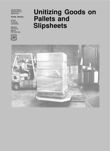
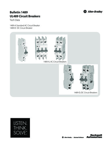
Jabiru Service Bulletin: J160 Family Engine Cooling19th April 2007JSB 016-14.4Level 2 – Medium Cowl LipAn aircraft which falls into this category is exposed to sufficient risk factors that the modificationlisted below is mandatory & is to be carried out during the next scheduled maintenance.The fixed lip shown in Figures 3 is available from Jabiru Aircraft. To fit, the lip is centred on thecowl, with it’s rearmost tips touching the rear of the cowl opening. The shape of the inside ofthe lip is marked out on the cowl, and the section of the cowl aft of the line is cut out. The lip isthen permanently attached using rivets or adhesive. Note that the smoothness of the transitionbetween the original cowl and the new lip affects the efficiency of the airflow, so the newly-cutedges must be sanded to remove any rough or sharp edges.Lip shown positioned in placetemporarily with tape.Figures 3 – Medium Cowl LipJSB016-1.docPage 4 of 7
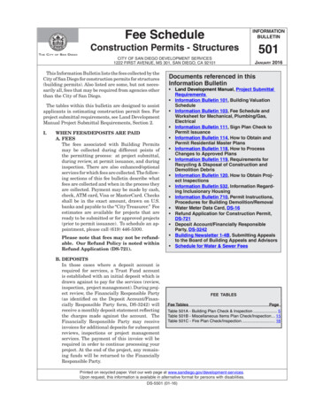
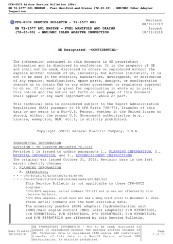
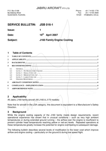
Jabiru Service Bulletin: J160 Family Engine Cooling19th April 2007JSB 016-14.5Level 3 – Large Cowl LipAn aircraft which falls into this category is exposed to sufficient risk factors that the modificationlisted below is mandatory & is to be carried out during the next scheduled maintenance.The fixed lip shown in Figures 5 is available from Jabiru Aircraft. To fit, the lip is centred on thecowl with it’s rearmost tips touching the rear of the cowl opening. The shape of the inside of thelip is marked out on the cowl, and the section of the cowl beyond aft of the line is cut out. Thelip is then permanently attached using adhesive & a layer of fibreglass. Note that thesmoothness of the transition between the original cowl and the new lip affects the efficiency ofthe airflow, so the newly-cut edges must be sanded to remove any rough or sharp edges.Note: Epoxy or Polyester resinmay be used.Prepare outer surface of lip & existing cowl forbonding by sanding off paint & gel-coat usingan orbital sander with 120 grit paper. Do nottouch with bare hands after sanding – blow offexcess dust using compressed airNew lipPrepare inner face of lip forbonding by removing peel plyFlock mixture bonding newlip to original cowl1 Layer fibreglassAT312 tape or50mm wide AF301 or50mm wide AF303 or50mm wide AF244Or equivalent.Centre over joint.Original lower cowl skinFigure 4 – Cross Section View Through Large Cowl Lip AttachmentNote: Figure 4 is shown with cowl sitting upside down (as shown in Figures 5 below).Figures 5 – Large Cowl LipJSB016-1.docPage 5 of 7
Jabiru Service Bulletin: J160 Family Engine CoolingJSB 016-119th April 20074.6Ongoing MonitoringOnce the aircraft has been modified the installation should continue to be monitored. If theinstallation continues to run at consistently high temperatures (best indicated by the amount ofrotation needed to restore head bolt tension during servicing) the operator may opt to fit the nextlargest lip or – in consultation with Jabiru Aircraft – to introduce a revised maintenance system.5Aircraft Condition NotesThe above bulletin assumes an engine installation in good condition, meeting factoryspecifications. For older aircraft, or for kit-built aircraft many other factors can affect enginecooling. The following is a sample list of such factors. Rubber seals – Rubber seals are used to close gaps between the engine and oil cooler andthe cowls but can deteriorate over time. For best cooling, these seals must be in goodcondition with no large gaps or openings. Gap or opening size is judged by area – so a gap15mm wide by 15mm long is generally acceptable, but a slot 10mm wide by 100mm long isexcessive. Ram Air Ducts – Over time ram air ducts can deteriorate. Check for tears or missing baffles& ensure the bolts holding the ducts to the cylinder heads are gripping on intact material. Alignment – Over time engine mount rubbers can deteriorate. Visually check that the oilcooler & ram air ducts align with their respective cowl openings. Oil level – over filling the engine can give high oil temperature readings and high levels of oilbeing blown out of the crankcase breather. Engine Intake Mixture – Engine temperatures can be increased by alterations to theengine’s fuel/air mixture which, in turn, can be affected by propeller or airframe loads.Jabiru Service Letter JSL 002 provides additional information on tuning of the Jabiru engine. Incorrect Valve Clearance Adjustment – In older (non hydraulic lifter) engines which requiremanual adjustment of valve clearances it is possible to have too little valve clearance.Among other symptoms, this can result in hot running of the engine in general and thevalves in particular. Correct valve clearance adjustment is essential for safe operationof the engine.6Compliance – Implementation:Compliance with the requirements of this bulletin is considered mandatory for all aircraftinvolved in Air Work operations (flying training, hire etc) and is strongly recommended for allother aircraft. Section 4 above gives details of the work required, and the recommendedtimeframe for carrying it out.JSB016-1.docPage 6 of 7
Jabiru Service Bulletin: J160 Family Engine CoolingJSB 016-1719th April 2007Airworthiness Note:Ensure that the latest issues of the aircraft servicing information are being used (engine manual,technical manual, flight manual).Where required, work called for by this Bulletin must be carried out by authorised personnel.For the aircraft detailed herein this means the owner, an RA-Aus Level 2 holder or a LicensedAircraft Maintenance Engineer (LAME) – as appropriate to the aircraft registration (or the localequivalent for aircraft outside of Australia).On completion of the work, the authorised person must note the completion of the actionsrequired by this bulletin in the aircraft’s maintenance logbook. This note should refer to thecompletion of maintenance requirements of this Service Bulletin, indicate the risk level found inTable 1, date the work and the identity (including licence number where appropriate) of theperson carrying out the work.JSB016-1.docPage 7 of 7
Aircraft Maintenance Engineer (LAME) - as appropriate to the aircraft registration (or the local equivalent for aircraft outside of Australia). On completion of the work, the authorised person must note the completion of the actions required by this bulletin in the aircraft's maintenance logbook. This note should refer to the