Transcription
LAB 45Edition 4 September 2021Schedules of Accreditation for CalibrationLaboratories
Schedules of Accreditation for Calibration LaboratoriesContents1.Introduction22.Calibration schedules - permanent laboratories33.Calibration schedules - multi-site laboratories44.Flexible scopes55.Opinions and interpretations66.Calibration and measurement capabilities67.Symbols and units118.Inclusion of reference to method or procedure and to equipment to be calibrated139.Final page of schedule14Appendix A - References15Appendix B - Example schedule entries15Changes since last editionMinor revisions only - two references to CMC amended to measurement uncertainty (§ 6.3, 6.4) andother minor editorial changes.1.Introduction1.1The definitive statement of the accredited scope of a calibration laboratory is the UKASSchedule of Accreditation which should be viewed after checking that the laboratory concernedis presently accredited by reference to www.ukas.com. The Schedule of Accreditation definesthe measurement capabilities, ranges and boundaries of the calibration activities for which theorganisation holds accreditation. It is therefore important that the Schedule of Accreditation ispresented in a manner that is scientifically meaningful and presents unambiguous informationin a manner that will be readily understood by the target audience.1.2This publication provides guidance on the format, presentation and content of Schedules ofAccreditation for UKAS accredited calibration laboratories. It is primarily aimed at UKASAssessment Managers and Technical Assessors but may also be of use to laboratories whenapplying for accreditation or when researching calibration schedules in support of obtainingtraceability of measurement. Use of this guidance will assist in the production of consistent andmeaningful schedules and will minimise the risk of customers and readers being misled.w: www.ukas.com t: 44(0)1784 429000 e: info@ukas.com United Kingdom Accreditation Service. UKAS copyright exists on all UKAS publications.Lab 45 Edition 4Page 2 of 17
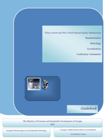
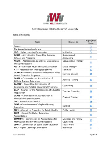
Schedules of Accreditation for Calibration Laboratories2.Calibration schedules - permanent laboratories2.1The first page of a Schedule of Accreditation for permanent laboratories normally contains thefollowing details:a) Name of the accredited entity, as stated in the associated Accreditation Certificate.b) Contact details, including name, telephone and fax numbers, email address and web sitedetails. These details are intended to assist the laboratory’s customers and therefore maybe different to those of the primary UKAS contact shown in our database.c) Statements to the effect that the organisation is accredited to ISO/IEC 17025 and thatcalibration is performed at the given address only.d) The UKAS calibration accreditation symbol with the organisation’s accreditation number.2.2An example is shown below.Schedule of Accreditationissued byUnited Kingdom Accreditation Service2 Pine Trees, Chertsey Lane, Staines-upon-Thames, TW18 3HR, UKNiceCal UK LimitedIssue No: 0010000Accredited toISO/IEC 17025:2017Issue date: 1 April 2021Calibration LaboratoryContact: Mr S I UnitHigh StreetTel: 44 (0) 1784 429000FelthamFax: 44 (0) 1784 429000MiddlesexE-Mail: si.unit@nicecal.comTW13 4UNWebsite: www.nicecal.comCalibration performed at the above address onlyCALIBRATION AND MEASUREMENT CAPABILITY (CMC)Measured QuantityInstrument or GaugeRangeExpanded MeasurementUncertainty(k 2)RemarksFirst page details for permanent laboratoriesw: www.ukas.com t: 44(0)1784 429000 e: info@ukas.com United Kingdom Accreditation Service. UKAS copyright exists on all UKAS publications.Lab 45 Edition 4Page 3 of 17
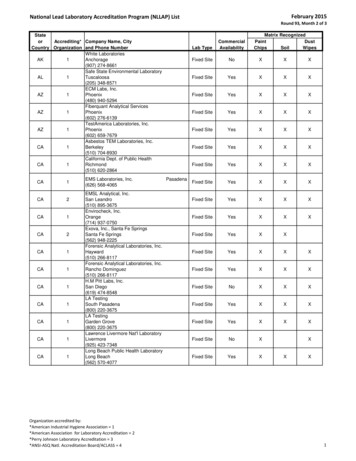
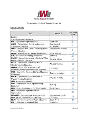
Schedules of Accreditation for Calibration Laboratories3.Calibration schedules - multi-site laboratories3.1The first page of a Schedule of Accreditation for multi-site laboratories normally contains thefollowing details:a) Name of the accredited entity, as stated in the associated Accreditation Certificate.b) Contact details, including name, telephone and fax numbers, email address and web sitedetails. These details are intended to assist the laboratory’s customers and therefore maybe different to those of the primary UKAS contact shown in our database. There may bedifferent contact details for each site, if appropriate.Statements to the effect that the organisation is accredited to ISO/IEC 17025 and thatcalibration is performed at the given address, at specified sites, or both. There willinevitably be restrictions on the type of customer sites at which calibrations can beperformed - these are due to, for example, the suitability of the environmental conditions,the space or facilities available and safety-related issues. This may therefore be aconsideration when phrasing the description of the types of site. The UKAS calibrationaccreditation symbol with the organisation’s accreditation number.c) A location code or identifier that indicates in subsequent pages where particularcalibrations may be performed.3.2An example is shown below.Schedule of Accreditationissued byUnited Kingdom Accreditation Service2 Pine Trees, Chertsey Lane, Staines-upon-Thames, TW18 3HR, UKNiceCal UK LimitedIssue No: 001Issue date: 1 April 2021Calibration LaboratoryContact: Mr S I UnitHigh StreetTel: 44 (0) 1784 429000FelthamFax: 44 (0) 1784 4290000000MiddlesexE-Mail: si.unit@nicecal.comAccredited toISO/IEC 17025:2017TW13 4UNWebsite: www.nicecal.comCalibration performed at the locations specified belowLocations covered by the organisation and their relevant activitiesLaboratory locations:Location detailsAddressHigh StreetFelthamMiddlesexTW13 4UNActivityLocation codeLocal contactMr S I UnitTel: 44 (0) 20 8917 8400Fax: 44 (0) 20 8917 8500Email: si.unit@nicecal.comWebsite: www.nicecal.comElectrical calibrationPw: www.ukas.com t: 44(0)1784 429000 e: info@ukas.com United Kingdom Accreditation Service. UKAS copyright exists on all UKAS publications.Lab 45 Edition 4Page 4 of 17
Schedules of Accreditation for Calibration LaboratoriesSite locations:Location detailsActivityThe location must be suitable forthe nature of the particularcalibrations undertaken and willbe the subject of contract reviewarrangements between thelaboratory and the customerLocation codeLocal contactProfessor W K HeisenbergTel: 44 (0) 20 8917 8400Fax: 44 (0) 20 8917 8500Email: uncertainty@nicecal.comWebsite: www.nicecal.comQuantum PhysicsSFirst page details for multi-site laboratoriesCALIBRATION AND MEASUREMENT CAPABILITY (CMC)Measured QuantityInstrument orGaugeRangeExpandedMeasurementUncertainty(k 2)RemarksLocation codeSecond page details for multi-site laboratories4.Flexible scopes4.1It is often considered that Calibration Schedules of the style used by UKAS are alreadyinherently flexible as they typically describe the boundaries of the accreditation in terms ofparameters and ranges, rather than solely by specification. This usually obviates any need toconsider further the matter of flexible scopes for calibration laboratories.4.2This method of presentation imparts flexibility as the laboratory can, in many cases, calibratevarious types of equipment where the measurements lie within the stated parametricboundaries.4.3However, should it be necessary to provide a schedule that specifically addresses FlexibleScopes for calibration laboratories, the following statement is suggested, either for the first pageor in the part of the schedule where Flexible Scopes have been agreed:The laboratory is accredited to ISO/IEC17025 for calibration activities in accordance with thedetails listed in this schedule. This may also include calibrations on the same or similar productsagainst standards, laboratory developed procedures or customer-specified methods that arenot specifically listed in this Schedule, providing that:(1) The method, procedure or standard does not introduce new principles of measurement.(2) The method, procedure or standard does not require measurements to be made outsidethe parametric boundaries defined in this Schedule.Information about flexible scopes of accreditation is available in UKAS document LAB 39 andEA document EA-2/05.w: www.ukas.com t: 44(0)1784 429000 e: info@ukas.com United Kingdom Accreditation Service. UKAS copyright exists on all UKAS publications.Lab 45 Edition 4Page 5 of 17
Schedules of Accreditation for Calibration Laboratories5.Opinions and interpretations5.1In cases where it has been agreed that the expression of Opinions and Interpretations isincluded in a calibration laboratory’s Schedule of Accreditation, the following statement issuggested for inclusion in that Schedule:Opinions regarding the results and interpretations of those results may be provided for themeasurements indicated.5.2It should be noted that assessment of conformity with specification does not require Opinionsand Interpretations to be included in the Schedule of Accreditation. This is because conformityassessment is based on stated and objective criteria, normally those presented in Appendix Mof M3003 [A1].6.Calibration and measurement capabilities6.1The capabilities provided by accredited calibration laboratories are described by the Calibrationand Measurement Capability (CMC), which expresses the lowest uncertainty of measurementthat can be achieved during a calibration. The CIPM-ILAC definition [A2] of the CMC is as follows:6.2A CMC is a calibration and measurement capability available to customers under normalconditions:(a) as published in the BIPM key comparison database (KCDB) of the CIPM MRA; or(b) as described in the laboratory’s scope of accreditation granted by a signatory to the ILACArrangement.6.3The CMC is normally used to describe the uncertainty that appears in an accredited calibrationlaboratory's schedule of accreditation and is the uncertainty for which the laboratory has beenaccredited using the procedure that was the subject of assessment. The measurementuncertainty should be calculated according to the procedures given in M3003 [A1] and shouldnormally be quoted as an expanded uncertainty at a coverage probability of 95%, which usuallyrequires the use of a coverage factor of k 2.6.4The measurement uncertainty may be described using various methods in the Schedule ofAccreditation:a)As a single value that is valid throughout the range.Example:Measured QuantityInstrument or GaugeGas pressure (Gauge)b)Range0 Pa to 500 PaExpanded MeasurementUncertainty (k 2)Remarks0.10 PaAs an explicit function of the measurand or of a parameter. Where the function includesquadrature addition in the measurement uncertainty statements, the notation Q[a, b]stands for the root-sum-square of the terms between brackets: Q[a, b] [a 2 b 2]1/2Example: (Linear addition in the first example and Quadrature addition in the second example)w: www.ukas.com t: 44(0)1784 429000 e: info@ukas.com United Kingdom Accreditation Service. UKAS copyright exists on all UKAS publications.Lab 45 Edition 4Page 6 of 17
Schedules of Accreditation for Calibration LaboratoriesMeasured QuantityInstrument or GaugeExpanded MeasurementUncertainty (k 2)RangeGas pressure (gauge), P100 Pa to 100 kPa0.010 % 1.0 PaGas pressure (gauge), P100 kPa to 1 MPaQ [10 Pa, 0.0040 % x P]c)RemarksAs a range of values. In such cases, the laboratory shall have procedures for determiningthe uncertainty at any given point within the range. Furthermore, the range should besufficiently restricted that the customer could make a reasonable estimate of the likelyuncertainty at any point within the range. Where a continuous range has been brokendown into sub-ranges for this purpose, the measurement uncertainty should match at thebreak points.Example:Measured QuantityInstrument or GaugeExpanded MeasurementUncertainty (k 2)Range0.5 to 0.9At 50 HzAC POWER FACTORRemarks0.0075 to 0.0036Maximum voltage 500 VMaximum current 25 AFor Power Factor MetersAs a matrix or table where the measurement uncertainty depends on the values of the measurand anda further parameter.Example:Measured QuantityInstrument or GaugeExpanded MeasurementUncertainty (k 2)RangeAC VOLTAGERemarksFor AC Voltmeters bycomparisonVoltagerange10 Hz to 100 Hz100 Hz to 30 kHz30 kHz to 200 kHz200 kHz to 500 kHz500 kHz to 1 MHz1 mV to 3.3 mV3.3 mV to 10 mV10 mV to 33 mV33 mV to 100 ation and Measurement Capability in % of value for AC voltages over the frequency ranges shownIn graphical form, providing there is sufficient resolution on each axis to obtain at leasttwo significant figures for the measurement uncertainty.6.5Open intervals (e.g. “ x”) are not permitted in the expression of CMCs.6.6It is sometimes the case that a laboratory may wish to be accredited for a measurementuncertainty that is larger than it can actually achieve. If the principles of M3003 [A1] are followedwhen constructing the uncertainty budget, the resulting expanded uncertainty should be arealistic representation of the laboratory’s measurement capability. If this is smaller than theuncertainty the laboratory wishes to be accredited for and report on their certificates ofcalibration, the implication is that the laboratory is uncomfortable in some way about thew: www.ukas.com t: 44(0)1784 429000 e: info@ukas.com United Kingdom Accreditation Service. UKAS copyright exists on all UKAS publications.Lab 45 Edition 4Page 7 of 17
Schedules of Accreditation for Calibration Laboratoriesmagnitude of the expanded uncertainty. If this is the case, then the contributions to theuncertainty budget should be reviewed and re-evaluated not arbitrarily expanded for a ‘safe’ or‘conservative’ estimate as this is not consistent with the GUM.6.7In cases where specific conditions are required in order to obtain the CMC, these conditionsshould be described in the Schedule of Accreditation, normally in the Remarks column.Example:Measured QuantityInstrument or GaugeRangeExpanded MeasurementUncertainty (k 2)RemarksFor AttenuatorsRF Attenuation6.80.3 MHz to 3 GHz0 dB to 40 dB40 dB to 62 dB62 dB to 80 dB0.047 dB0.092 dB0.90 dB7 mm 50 coaxial line fittedwith GPC 7 or Type Nconnectors. The uncertaintyis for devices with input andoutput VRC not exceeding0.2.The CMC should always be stated numerically and not exclusively by reference to a standardor other document that describes the measurements undertaken.Incorrect Example:Measured QuantityInstrument or GaugeNon automatic weighing machinesRangeUp to 1000 kgExpanded MeasurementUncertainty (k 2)Uncertainties quoted will depend on theperformance of the weighing machineunder calibration, and will not be lessthan the uncertainty of calibration of theweights used for the calibration.RemarksWeights are available in OIMLClass E2 from 10 mg to 200 g,Class F1 from 10 mg to 10 kgand class M1 from 1 kg to 20kg, 2 x 200 kg and 2 x 500 kg,to a total of 1000 kgCorrect Example:Measured QuantityInstrument or GaugeNon automatic weighing machinesusing OIML methods6.9Range10 mg to 10 g10 g to 50 g50 g to 30 kg30 kg to 1000 kgExpanded MeasurementUncertainty (k 2)0.025 mg2.0 mg/kg10 mg/kg100 mg/kgRemarksWeights are available in OIMLClass E2 from 10 mg to 200 g,Class F1 from 10 mg to 10 kgand class M1 from 1 kg to 20kg, 2 x 200 kg and 2 x 500 kg,to a total of 1000 kgIt should be particularly noted that relative expressions, such as percentages, are notpermissible when the range of the quantity values includes, or is close to, zero. Under suchconditions, an absolute term must also be present; either on its own or in conjunction with therelative term.w: www.ukas.com t: 44(0)1784 429000 e: info@ukas.com United Kingdom Accreditation Service. UKAS copyright exists on all UKAS publications.Lab 45 Edition 4Page 8 of 17
Schedules of Accreditation for Calibration LaboratoriesExample:Measured QuantityInstrument or GaugeRangeExpanded MeasurementUncertainty (k 2)RemarksDC Voltage0 V to 1 V25 ppmIncorrectDC Voltage0 V to 1 V25 μV/V 5.0 μVCorrectUsing a comparison meterDC Current0 mA to 20 mA2.5 μA6.10CorrectUsing a shunt and voltmeterParticular care should be taken when the unit itself is normally expressed in percentage terms;examples are relative humidity (%rh) and amplitude modulation (% AM). For example,50 %rh 10 %rh means the boundaries are 40 %rh and 60 %rh, whereas50 %rh 10 % means the boundaries are 45 %rh and 55 %rh.Under circumstances of this nature the presentation of the CMCs must be such that there is noambiguity in interpretation.6.11Mathematical functions should not be used when the measurand is a single, specific value,rather than a range of values. Rather, the expression should be evaluated, and a single valueof measurement uncertainty stated.Example:Measured QuantityInstrument or GaugeRangeExpanded MeasurementUncertainty (k 2)RemarksDC Resistance (specific value)100 Ω25 ppm 3.0 mΩIncorrectDC Resistance (specific value)100 Ω39 mΩFor ResistorsUsing a bridgeCorrect6.12The number of figures in a measurement uncertainty declaration should always reflect practicalmeasurement capability. In view of the process for estimating uncertainties it is seldom justifiedto present more than two significant figures. Using less than two significant figures can,however, introduce unacceptably large rounding errors. The measurement uncertainty shouldtherefore be stated to two significant figures, using the normal rules of rounding, unless thereare valid technical reasons for doing otherwise.Examples:IncorrectCorrect2 μm0.1 MPa5 mg7.17 nA2.0 μm0.098 MPa4.7 mg7.2 nAWhen the measurement uncertainty value is provided by a function, the coefficients shouldhave no more significant figures than are required for the calculation to be accurate whenrounded to two significant figures.6.13It is frequently the case that a measurement capability is broken down into rangescorresponding to those available on the measuring instrument upon which the capability isw: www.ukas.com t: 44(0)1784 429000 e: info@ukas.com United Kingdom Accreditation Service. UKAS copyright exists on all UKAS publications.Lab 45 Edition 4Page 9 of 17
Schedules of Accreditation for Calibration Laboratoriesbased. Under such circumstances, the ranges described in the Schedule of Accreditation shouldcorrespond to the nominal range change points, as in the example below.CorrectMeasured QuantityInstrument or GaugeIncorrectRangeMeasured QuantityInstrument or GaugeRangeFor voltmeters by comparisonDC Voltage0 mV to 200 mV200 mV to 2 V2 V to 20 V20 V to 200 V200 V to 1000 VDC Voltage0 mV to 200 mV 200 mV to 2 V 2 V to 20 V 20 V to 200 V 200 V to 1000 V0 mV to 200 mV201 mV to 2 V2 .01V to 20 V20.1 V to 200 V201 V to 1000 V6.14The rationale behind this reasoning is as follows:a) The intermediate ranges contain values that are repeated in the previous and subsequentranges. So the question arises: “What is the measurement uncertainty at these repeatedpoints?”b) The exact stimulus required to switch between ranges on any instrument will depend onthe particular calibration characteristics of each range of the instrument, including themeasurement uncertainty. That stimulus can, therefore, never be truly known. Hence,there is no point in attempting to avoid the repetition; for example, by use of the “ ”symbol or by leaving small gaps in the capability.c) The laboratory’s procedures or records should contain sufficient information to define therange that was used in a particular calibration and hence the correct uncertainty,corresponding to that range, may be reported.6.15In the example above, the ranges designated in multiples of “2” are nominal, as the theoreticalchange over point is 1 least significant digit lower. For example, the 200 mV range actually hasa full-scale value of 199.9999 mV. However, there is no point in stating the capability to such adegree of resolution, for the reasons stated in b) above.6.16Where the normative standard defines an uncertainty calculation methodology which differsfrom the calibration measurement uncertainty, for example the test value uncertainty definedfor the verification of callipers to ISO 13385-1, the test value uncertainty will be reported alongwith a comment making it clear what has and has not been included in the uncertainty analysis,in line with the definition provided by the standard. For example, “the test value uncertainty hasbeen evaluated in accordance with the relevant ISO standard” and “calliper resolution andcalliper repeatability have not been considered in the test value uncertainty”.6.17In dimensional calibration, the schedules of accreditation for the calibration of basic dimensionalmeasuring tools and equipment have historically reported a CMC for parameters most relevantto end users. This method however does not provide transparency with regards to auxiliarymeasurements such as flatness and parallelism of micrometer measuring faces etc. Theseadditional measurement techniques shall be listed on the schedule of accreditation along withthe corresponding measurement uncertainty.w: www.ukas.com t: 44(0)1784 429000 e: info@ukas.com United Kingdom Accreditation Service. UKAS copyright exists on all UKAS publications.Lab 45 Edition 4Page 10 of 17
Schedules of Accreditation for Calibration Laboratories6.18The measurement uncertainty should where practicable be expressed in terms of themeasurand, however for calibrations in which various measurands 𝑠 are possible dependingupon the nature of the response 𝑥 from the calibrated item, the CMC may be stated as theequivalent uncertainty expressed in the units of the reference quantity 𝑞, rather than in terms ofthe measurand 𝑠 𝑠(𝑥, 𝑞), such that 𝑞𝑢(𝑞) 𝑢(𝑠). 𝑠For example, suppose that the calibration of a flow sensor at flowrate 𝐹 establishes an output𝐹frequency 𝑓 and this is usually reported in terms of a meter factor ℎ .𝑓The CMC can be reported in terms of the reference quantity 𝐹 (rather than the measurand ℎ)by calculating 𝐹𝑢(𝐹) 𝑢(ℎ) 𝑓 𝑢(ℎ) ℎ6.19Testing laboratories, in most cases, conduct their tests against internationally publishedstandards and the associated testing schedule will contain references to these standards. Mostcalibration activities are conducted using documented in-house methods that have beendemonstrated to provide the stated CMCs by means of uncertainty analysis. Consequently,there is, in most cases, no requirement to list normative references in calibration schedules.However, where such standards are used, they should be included in the Remarks column asin the following example:Measured QuantityInstrument or GaugeExpanded MeasurementUncertainty (k 2)RangeRemarksRELATIVE MAGNETIC PERMEABILITY, µrFor low magnetic permeabilitymaterials( r - 1) from 0.001 to 1.5(DC)0.20 %In accordance withBS 5884:19877.Symbols and units7.1It is recommended that only units of the SI and those units recognised for use with the SI shouldbe used to express the values of quantities and of the associated measurement uncertainty.Nevertheless, other commonly used units may be used where considered necessary for theintended audience.7.2ILAC P14 4.3 states “Because of the ambiguity of definitions, the use of terms “PPM” and “PPB”are not acceptable”. Therefore, the terms “ppm” and “ppb” should not be used. These terms canbe replaced by a ratio of engineering units e.g., μV/V which would have the same numeric valueas ppm, or through the use of “%” or parts in 106.7.3There are also units that are not part of the SI system but the use of which may be necessaryfor historical purposes or for calibration of instruments that are scaled in such units. Forexample, many dimensional measuring instruments are available that are scaled in inch units,although the SI definition of length relates to the metre. In such circumstances, the Schedule ofAccreditation should use the correct SI unit but with a note such as “All linear calibrations maybe given in inch units”.7.4One specific unit that is not mentioned in the SI system is that of relative humidity. It isrecommended that the expression “%rh” be used for this quantity. Revolutions per minute isrecommended to be shortened to “rpm”. Other commonly encountered units that are not definedw: www.ukas.com t: 44(0)1784 429000 e: info@ukas.com United Kingdom Accreditation Service. UKAS copyright exists on all UKAS publications.Lab 45 Edition 4Page 11 of 17
Schedules of Accreditation for Calibration Laboratoriesin the SI system relate to units of time, in particular days, hours and minutes. The following arerecommended for use in Schedules of Accreditation:7.5NameSymbolValue in SI unitsminute (time)hourdayminhd1 min 60 s1 h 60 min 3600 s1 d 24 h 86 400 sAbbreviations such as sec, cc, or mps are to be avoided and only standard unit symbols, prefixsymbols, unit names, and prefix names should be used.Examples:Correct: s or second; cm3 or cubic centimetre; ms-1, m/s or metre per secondIncorrect: sec; cc; mps7.6Unit symbols are unaltered in the plural.Example:Correct: l 75 cmIncorrect: l 75 cms7.7Unit symbols (or names) are not modified by the addition of subscripts or other information. Thefollowing form, for example, is used instead.Correct: Vmax 1000 VIncorrect: V 1000 Vmax7.8The dash (-) should not be used to indicate a range of values, due to ambiguity with the negativeoperator (minus sign). The word “to” should be used instead.Example:Correct: 0.8 g/ml to 1.0 g/mlIncorrect: 0.8 g/ml - 1.0 g/ml7.9The unit should be repeated for each quantity value, either explicitly or by the use ofparentheses.Example:Correct: 20 C to 30 C or (20 to 30) CIncorrect: 20 to 30 C7.10There is a space between the numerical value and unit symbol, even when the value is used inan adjectival sense, except in the case of superscript units for plane angle.Examples:Correct: a 25 kg massCorrect: 100 mVCorrect: an angle of 2 3’ 4”Correct: 100 CCorrect: 0.25 %7.11Incorrect: a 25-kg massIncorrect: 100mVIncorrect: an angle of 2 3 ’ 4 ”Incorrect: 100 CIncorrect: 0.25%In cases where a number is not used as part of an expression, there is no space betweenmathematical operators (such as “ ” or “-” signs) and the associated number. This is known asa monadic operator.w: www.ukas.com t: 44(0)1784 429000 e: info@ukas.com United Kingdom Accreditation Service. UKAS copyright exists on all UKAS publications.Lab 45 Edition 4Page 12 of 17
Schedules of Accreditation for Calibration LaboratoriesExamples:Correct: -20 CCorrect: -100 mV to 100 mVIncorrect: - 20 CIncorrect: - 100 mV to 100 mVNOTE: the absence of a “ ” or “-” sign implies that the value is positive, however the use ofthe “ ” sign is encouraged where negative values are also included, as in the second exampleabove.7.12However, if the number and symbol are part of an expression (e.g. a b), then spaces shouldbe used. This is known as a dyadic operator.8.Inclusion of reference to method or procedure and to equipment to becalibrated8.1If the descriptions in the other columns of the Schedule do not include a reference to the methodor procedure used; then such a description shall be placed in the Remarks column. This isrequired to comply with ISO/IEC 17011:2017 so that the reader may appreciate the nature ofthe calibration or may enquire further about the reference given.8.2This reference may be in the form of the principle deployed, or the equipment used, or areference to a documented procedure: For example:By calibration against a pressure balanceBy comparison with a voltage reference sourceMethods consistent with EURAMET CG188.3If the wording in the other columns does not describe the type of equipment or material to becalibrated, then this must be added to the Parameter or the Remarks column when this isrequired for the interpretation of the capability. For laboratories with multiple parameters perequipment this may be provided in the equipment list presented in the schedule preview paneof those laboratories on the UKAS website.w: www.ukas.com t: 44(0)1784 429000 e: info@ukas.com United Kingdom Accreditation Service. UKAS copyright exists on all UKAS publications.Lab 45 Edition 4Page 13 of 17
Schedules of Accreditation for Calibration Laboratories9.Final page of schedule9.1In order to assist laboratories’ customers with the interpretation of the information provided incalibration schedules, the information presented below should be included as the final page.This information is a short summary of the recommendations of this document, LAB 45.Appendix - Calibration and Measurement CapabilitiesIntroductionThe definitive statement of the accreditation status of a calibration laboratory is the Accreditation Certificate and the associatedSchedule of Accreditation. This Schedule of Accreditation is a critical document, as it defines the measurement capabilities, rangesand boundaries of the calibration activities for which the organisation holds accreditation.Calibration and Measurement Capabilities (CMCs)The capabilities provided by accredited calibration laboratories are described by the Calibration and Measurement Capability (CMC),which expresses the lowest measurement uncertainty that can be achieved during a calibration. If a particular device undercalibration itself contributes significantly to the uncertainty (for example, if it has limited resolution or exhibits significant nonrepeatability) then the uncertainty quoted on a calibration certificate will be increased to account for such factors.The CMC is normally used to describe the uncertainty that appears in an accredited calibration laboratory's schedule of accreditationand is the uncertainty for which the laboratory has been accredited using the procedure that was the subject of assessment. Themeasurement uncertainty is calculated according to the procedures given in the GUM and is normally stated as an expandeduncertainty at a coverage probability of 95 %, which usually requires the use of a coverage factor
2. Calibration schedules - permanent laboratories 3 3. Calibration schedules - multi-site laboratories 4 4. Flexible scopes 5 5. Opinions and interpretations 6 6. Calibration and measurement capabilities 6 7. Symbols and units 11 8. Inclusion of reference to method or procedure and to equipment to be calibrated 13 9. Final page of schedule 14