Transcription
PLEASE READThis user manual is from the manufacturer — JiveCommunications may not support some features discussedin this document.Please see our online documentation or contact us for acomplete list of supported features.Thanks for choosing Jive!
ADMINISTRATIONGUIDECisco Small BusinessSPA2102, SPA3102, SPA8000, SPA8800, PAP2TAnalog Telephone Adapters
Cisco and the Cisco logo are trademarks or registered trademarks of Cisco and/or its affiliates in the U.S. and other countries. To view a list of Cisco trademarks,go to this URL: www.cisco.com/go/trademarks. Third-party trademarks mentioned are the property of their respective owners. The use of the word partnerdoes not imply a partnership relationship between Cisco and any other company. (1110R) 2011 Cisco Systems, Inc. All rights reserved.OL-17901-05
ContentsChapter 1: Introducing Cisco Small Business Analog Telephone Adapters10Comparison of ATA Devices11ATA Connectivity Requirements14PAP2T Connectivity15SPA2102 Connectivity16SPA3102 Connectivity17SPA8000 Connectivity18SPA8800 Connectivity20ATA Software Features21Voice Supported Codecs21SIP Proxy Redundancy22Other ATA Software Features23Chapter 2: Basic Administration and Configuration31Basic Services and Equipment Required31Downloading Firmware32Basic Installation and Configuration32Upgrading the Firmware for the ATA Device32Setting up Your ATA Device33Using the Administration Web Server34Connecting to the Administration Web Server35Setting Up the WAN Configuration for Your ATA Device35Registering to the Service Provider37Advanced Configurations38Upgrading, Rebooting, and Resyncing Your ATA Device38Upgrade URL38Resync URL39Reboot URL39Provisioning Your ATA Device40Provisioning Capabilities40Configuration Profile41Cisco Small Business ATA Administration Guide3
ContentsChapter 3: Configuring Your System for ITSP InteroperabilityNetwork Address Translation (NAT) and Voice over IP (VoIP)4242NAT Mapping with Session Border Controller43NAT Mapping with SIP-ALG Router43Configuring NAT Mapping with a Static IP Address43Configuring NAT Mapping with STUN45Determining the Router’s NAT Mechanism47Firewalls and SIP48Configuring SIP Timer Values48Chapter 4: Configuring Voice Services49Supported Codecs49Using a FAX Machine50Fax Troubleshooting51Managing Caller ID Service53Silence Suppression and Comfort Noise Generation55Configuring Dial Plans56About Dial Plans56Editing Dial Plans65Secure Call Implementation66Enabling Secure Calls66Secure Call Details67Using a Mini-Certificate68Generating a Mini Certificate68SIP Trunking and Hunt Groups on the SPA800070About SIP Trunking71Setting the Trunk Group Call Capacity73Inbound Call Routing for a Trunk Group73Contact List for a Trunk Group74Outgoing Call Routing for a Trunk Group76Configuring a Trunk Group77Cisco Small Business ATA Administration Guide4
ContentsTrunk Group Management78Setting the Hunt Policy80Additional Notes About Trunk Groups80Chapter 5: Configuring Music on HoldUsing the Internal Music Source for Music On Hold8181Using the Internal Music Source81Changing the Music File for the Internal Music Source82Configuring a Streaming Audio Server83About the Streaming Audio Server83Configuring the Streaming Audio Server85Using the IVR with an SAS Line86Chapter 6: Configuring the PSTN (FXO) Gateway on the SPA310287Connecting to PSTN and VoIP Services87How VoIP-To-PSTN Calls Work88One-Stage Dialing (SPA3102 and SPA8800)88Two-Stage Dialing (SPA3102)89How PSTN-To-VoIP Calls WorkTerminating Gateway Calls9091VoIP Outbound Call Routing (SPA3102)92Configuring VoIP Failover to PSTN93Sharing One VoIP Account Between the FXS and PSTN Lines (SPA3102)93Other Options94PSTN Call to Ring Line 1 (SPA3102)94Symmetric RTP (SPA3102 and SPA8800)94Call Progress Tones (SPA3102 and SPA8800)95Call Scenarios95PSTN to VoIP Call with and Without Ring-Thru96VoIP to PSTN Call With and Without Authentication96Call Forwarding to PSTN Gateway (SPA3102 and SPA8800)98Cisco Small Business ATA Administration Guide5
ContentsAppendix A: ATA Routing Field ReferenceRouter Status page100100Product Information section101System Status section101WAN Status page102Internet Connection Settings section102Static IP Settings section103PPPoE Settings section103Optional Settings section104MAC Clone Settings section105Remote Management section105QOS Settings section105VLAN Settings section106LAN Status page106Networking Service section106LAN Networking Settings section107Static DHCP Lease Settings section107Application page107Port Forwarding Settings section108DMZ Settings section108Miscellaneous Settings section109System Reserved Ports Range section109Appendix B: ATA Voice Field ReferenceInfo page110111Product Information section111System Status section112Line Status section112System Information section (PAP2T)115PSTN Line Status section (SPA3102)115Trunk Status section (SPA8000)118Cisco Small Business ATA Administration Guide6
ContentsSystem page119System Configuration section119Internet Connection Type section (PAP2T)120Optional Network Configuration section (PAP2T)120Miscellaneous Settings section (not used with PAP2T)121SIP page122SIP Parameters section122SIP Timer Values (sec) section124Response Status Code Handling section126RTP Parameters section127SDP Payload Types section129NAT Support Parameters section130Trunking Parameters section (SPA8000)133Regional page134Call Progress Tones section135Distinctive Ring Patterns section137Distinctive Call Waiting Tone Patterns section138Distinctive Ring/CWT Pattern Names section139Ring and Call Waiting Tone Spec section140Control Timer Values (sec) section141Vertical Service Activation Codes section143Vertical Service Announcement Codes section (SPA2102, SPA8000)149Outbound Call Codec Selection Codes section149Miscellaneous section151Line page155Line Enable section156Streaming Audio Server (SAS) section157NAT Settings section158Network Settings section159SIP Settings section160Call Feature Settings section163Proxy and Registration section164Cisco Small Business ATA Administration Guide7
ContentsSubscriber Information section166Supplementary Service Subscription section167Audio Configuration section169Gateway Accounts section (SPA3102)174VoIP Fallback to PSTN section (SPA3102 and SPA8800)175Dial Plan section175FXS Port Polarity Configuration section177VoIP-to-PSTN Gateway Setup section (SPA8800)177FXO Timer Values (sec) section (SPA8800)179PSTN Disconnect Detection section (SPA8800)180International Control section (SPA8800)183Call Forward, Speed Dial, Supplementary Services, and Ring Settings(SPA8000 and SPA8800)184Trunk Group page (SPA8000)185Line Enable section185Network Settings section185SIP Settings section186Subscriber Information section189Dial Plan section191NAT Settings section191Proxy and Registration section192PSTN Line page (SPA3102)194Line Enable section194NAT Settings section195Network Settings section195SIP Settings section196Proxy and Registration section199Subscriber Information section201Audio Configuration section202Dial Plans section205VoIP-To-PSTN Gateway Setup section206VoIP Users and Passwords (HTTP Authentication) section208Cisco Small Business ATA Administration Guide8
ContentsRing Settings section209FXO (PSTN) Timer Values (sec) section209PSTN Disconnect Detection section211International Control (Settings) section214User page216Call Forward Settings section217Selective Call Forward Settings section218Speed Dial Settings section218Supplementary Service Settings section219Distinctive Ring Settings section220Ring Settings section221PSTN User page (SPA3102)222PSTN-To-VoIP Selective Call Forward Settings section222PSTN-To-VoIP Speed Dial Settings section223PSTN Ring Thru Line 1 Distinctive Ring Settings section223PSTN Ring Thru Line 1 Ring Settings section223Appendix C: Troubleshooting224Appendix D: Environmental 00230SPA8800230Appendix E: Where to Go From Here231Product Resources231Related Documentation232Cisco Small Business ATA Administration Guide9
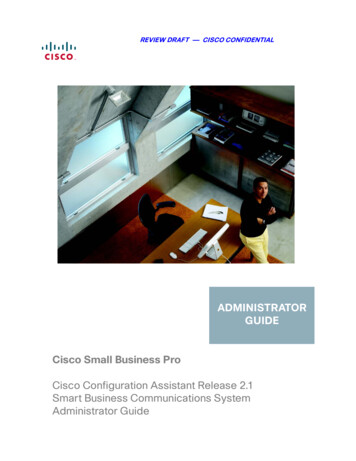
1Introducing Cisco Small Business AnalogTelephone AdaptersThis guide describes the administration and use of Cisco Small Business analogtelephone adapters (ATAs). These ATA devices are a key element in the end-toend IP Telephony solution. An ATA device provides user access to Internet phoneservices through one or more standard telephone RJ-11 phone ports usingstandard analog telephone equipment. The ATA device connects to a wide area IPnetwork, such as the Internet, through a broadband (DSL or cable) modem orrouter. The ATA can be used with an onsite call-control system such as theSPA9000 Voice System or legacy PBX, or with an Internet-based call-controlsystem.Figure 1 ATA Deployment without Onsite Call inksys ATABroadband CPE(DSL, cable,fixed wireless)VIP infrastructureSIP proxyCisco Small Business ATA Administration GuideVPSTN187254Layer 310
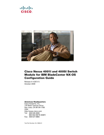
1Introducing Cisco Small Business Analog Telephone AdaptersComparison of ATA DevicesATA Deployment with Onsite Call ControlOptional On-SiteCall Control(SPA9000 or Legacy PBX)Telephone/faxVLinksys ATABroadbandEthernetBroadband CPE(DSL, cable,fixed wireless)VoicegatewayLayer 3IP infrastructureVPSTNSIP proxy194487Figure 2This chapter introduces the functionality of the ATA devices and describes thefeatures that are available.Refer to the following topics: “Comparison of ATA Devices,” on page 11 “ATA Connectivity Requirements,” on page 14 “ATA Software Features,” on page 21Comparison of ATA DevicesEach ATA device is an intelligent low-density Voice over IP (VoIP) gateway thatenables carrier-class residential and business IP Telephony services deliveredover broadband or high-speed Internet connections. An ATA device maintains thestate of each call it terminates and makes the proper reaction to user input events(such as on/off hook or hook flash). The ATA devices use the Session InitiationProtocol (SIP) open standard so there is little or no involvement by a “middle-man”server or media gateway controller. SIP allows interoperation with all ITSPs thatsupport SIP.The ATA Models table summarizes the ports and features provided by the ATAdevices described in this document.Cisco Small Business ATA Administration Guide11
1Introducing Cisco Small Business Analog Telephone AdaptersComparison of ATA DevicesATA 2T2—1—2Voice adapter with two FXS ports.SPA21022—112Voice adapter with router.SPA310211111Voice adapter with router and PSTNconnectivity.SPA80008—1Maintenanceonly8Voice adapter with support for up toeight FXS devices. Supports SIPTrunking for inbound call routing totrunk groups. Also has a single multiport RJ-21 50-pin connector foroptional patch-panel connectivity.SPA8800441Maintenanceonly8Voice adapter with support for up tofour FXS phones and up to four FXOPSTN lines. Also has a single multiport RJ-21 50-pin connector foroptional patch-panel connectivity.NOTE Additional ATA models, Cisco SPA112, SPA122, and SPA232D are covered inseparate Quick Start Guides and administration guides. For links to all ATAdocumentation, see www.cisco.com/go/smallbizvoicegateways.NOTE The information contained in this guide is not a warranty from Cisco. Customersplanning to use ATA devices in a VoIP service deployment are advised to test allfunctionality they plan to support before putting the ATA device in service. Byimplementing ATA devices with the SIP protocol, intelligent endpoints at the edgesof a network perform the bulk of the call processing. This allows the deployment ofa large network with thousands of subscribers without complicated, expensiveservers.Cisco Small Business ATA Administration Guide12
1Introducing Cisco Small Business Analog Telephone AdaptersComparison of ATA DevicesThe following figure illustrates how the different ATA devices provide voiceconnectivity in a VoIP network.Figure 3How ATAs Provide Voice ConnectivityEthernet/WirelessLANSPA2102WRP400, RTP300,WRTP54G, andSPA2102Fax (up to ,SPA3102AG310InternetAnalog phone(up to 8 irelessLANSPA3102PSTN187255Ethernet/WiredLAN The PAP2T and the SPA8000 provide FXS ports to connect fax machines andanalog phones to IP telephone services. The SPA3102 and the SPA8800 act as SIP-PSTN gateways.Cisco Small Business ATA Administration Guide13
Introducing Cisco Small Business Analog Telephone AdaptersATA Connectivity Requirements1NOTE For information about the WRP400, see the WRP400 Administration Guide.ATA Connectivity RequirementsAn ATA device can be connected to a local router, or directly to the Internet. Eachphone connected to an RJ-11 (analog) port on the ATA device connects to otherdevices through SIP, which is transmitted over the IP network.In order to ensure connectivity between the devices connected to its FXS ports,the ATA device requires the following functionality to be supplied on the networkconnected to its Ethernet port: Connection to an IP router with hairpinning support Connection to an outbound Proxy serverWhen a phone connected to the ATA device communicates with another phone, itsends a SIP packet onto the internal LAN. The packet is then forwarded to theexternal LAN or directly to the Internet. The source address and source port on theoriginal packet are assigned by the ATA device DHCP server. The address andport are translated by the ATA device using Network Address Translation (NAT)and Port Address Translation (PAT). The packet is then routed back to the internalnetwork on the ATA device by the local router or the ISP router.Problems can occur with calls between phones connected to the ATA devicewhen an outbound proxy or a router with hairpinning support is not available. TheATA device cannot directly connect the two telephone devices, but requires alocal or remote router to route the packet back to its destination on the localnetwork from which it originated.The necessary routing can be provided by a router with hairpinning support, or byan outbound SIP proxy, which is typically provided by the Internet TelephonyService Provider (ITSP). When relying on the ITSP for interconnecting phones onthe ATA device, local phones connected to the ATA device are unable tocommunicate with each other if the Internet connection is not available for anyreason. It is recommended you connect the ATA device to a local router thatprovides hairpinning support to prevent this problem.Cisco Small Business ATA Administration Guide14
1Introducing Cisco Small Business Analog Telephone AdaptersATA Connectivity RequirementsPAP2T ConnectivityAs shown in the following figure, the PAP2T has two FXS ports (voice lines 1 and2).AdministrativeIVR (Line 1 orLine 2)Line 1EthernetportIP Router (withhairpinning) orBroadband modemISPLine 2LANInternetWANPAP2TITSP187420IPNOTE The IVR functions are accessed by connecting an analog telephone to Line 1. For proper operation, the service provider should use an Outbound Proxy toforward all voice traffic when the PAP2T is located behind a router. Ifnecessary, explicit port ranges can be specified for SIP and RTP.Cisco Small Business ATA Administration Guide15
1Introducing Cisco Small Business Analog Telephone AdaptersATA Connectivity RequirementsSPA2102 ConnectivityAs shown in the following illustration, the SPA2102 has two FXS ports (voice lines1 and 2).AdministrativeIVR (Line 1 orLine 2)Line 1EthernetportIP Router (withhairpinning) orBroadband modemISPLine 102ITSPBy default, the device attached to the LAN port is assigned the network address192.168.0.0 with a subnet mask of 255.255.255.0. If there is a network addressconflict with a device on the Ethernet port, the network address of the device onthe LAN port is automatically changed to 192.168.1.0.NOTE The IVR functions are accessed by connecting an analog telephone to Line 1. For proper operation, the service provider should use an Outbound Proxy toforward all voice traffic when the SPA2102 is located behind a router. Ifnecessary, explicit port ranges can be specified for SIP and RTP.Cisco Small Business ATA Administration Guide16
1Introducing Cisco Small Business Analog Telephone AdaptersATA Connectivity RequirementsSPA3102 ConnectivityAs shown in the following figure, the SPA3102 has one FXS port (voice line 1).AdministrativeIVR (Line 1 orLine 2)Line 1PSTNEthernetportPSTNLine 1IP Router (withhairpinning) orBroadband 259SPA3102ITSPBy default, the device on the LAN port is assigned the network address192.168.0.0 with a subnet mask of 255.255.255.0. If there is a network addressconflict with a device on the Ethernet port, the network address of the device onthe LAN port is automatically changed to 192.168.1.0.NOTE The IVR functions are accessed by connecting an analog telephone to Line 1. For proper operation, the service provider should use an Outbound Proxy toforward all voice traffic when the SPA3102 is located behind a router. Ifnecessary, explicit port ranges can be specified for SIP and RTP.Cisco Small Business ATA Administration Guide17
1Introducing Cisco Small Business Analog Telephone AdaptersATA Connectivity RequirementsSPA8000 ConnectivityAs shown in the following illustration, the SPA8000 consists of eight voice ports(voice lines 1-8).AdministrativeIVR (Line 1 orLine 2)8 FXS (RJ-11/RJ-21 ) portsIP Router (withhairpinning) orBroadband modemSPA8000NAT/PATInternal DHCPLine 2serverLine 1EthernetportISPLANInternetWANIPAUXportITSPLine 3AdministrationPCLine 4Line 5Line 6Line 8187256Line 7By default, the device on the AUX port is assigned the network address192.168.0.0 with a subnet mask of 255.255.255.0. If there is a network addressconflict with a device on the Ethernet port, the network address of the device onthe AUX port is automatically changed to 192.168.1.0.In the illustration, one fax machine is connected to each pair of ports to illustratethat only one T.38 connection is supported by each of the four pairs of RJ-11 ports.Up to four fax machines can be connected to the SPA8000 router, but they must bedistributed as shown.Cisco Small Business ATA Administration Guide18
Introducing Cisco Small Business Analog Telephone AdaptersATA Connectivity Requirements1NOTE You can use line 1 or line 2 to access the IVR functions. For proper operation, the service provider should use an Outbound Proxy toforward all voice traffic when the SPA8000 is located behind a router. Ifnecessary, explicit port ranges can be specified for SIP and RTP. The SPA8000 is not designed to forward IP packets to devices connected to itsAUX port and that configuration is not supported. The SPA8000 also can be configured with trunk groups and trunk lines. See“SIP Trunking and Hunt Groups on the SPA8000,” on page 70.Cisco Small Business ATA Administration Guide19
1Introducing Cisco Small Business Analog Telephone AdaptersATA Connectivity RequirementsSPA8800 ConnectivityAs shown in the following figure, the SPA8800 has four voice modules that eachprovide 1 FXS port and 1 FXO port.AdministrativeIVR (Line 1 orLine 2)8 FXS (RJ-11/RJ-21 ) portsIP Router (withhairpinning) orBroadband modemSPA8000NAT/PATInternal DHCPLine 2serverLine 1EthernetportISPLANInternetWANIPAUXportITSPLine 3AdministrationPCLine 4Line 5Line 6Line 8187256Line 7By default, the device on the LAN port is assigned the network address192.168.0.0 with a subnet mask of 255.255.255.0. If there is a network addressconflict with a device on the Ethernet port, the network address of the device onthe LAN port is automatically changed to 192.168.1.0.Cisco Small Business ATA Administration Guide20
Introducing Cisco Small Business Analog Telephone AdaptersATA Software Features1NOTE The IVR functions are accessed by connecting an analog telephone to Phone 1only. For proper operation, the service provider should use an Outbound Proxy toforward all voice traffic when the SPA8800 is located behind a router. Ifnecessary, explicit port ranges can be specified for SIP and RTP.ATA Software FeaturesThe ATA device is a full featured, fully programmable phone adapter that can becustom provisioned within a wide range of configuration parameters. This sectioncontains a high-level overview of features to provide a basic understanding of thefeature breadth and capabilities of the ATA device.The following sections describe the factors that contribute to voice quality: “Voice Supported Codecs,” on page 21 “SIP Proxy Redundancy,” on page 22 “Other ATA Software Features,” on page 23Voice Supported CodecsNegotiation of the optimal voice codec sometimes depends on the ability of theATA device to match a codec name with the codec used by the far-end device.The ATA device allows the network administrator to individually name the variouscodecs that are supported so that the ATA device can successfully negotiate thecodec with the far-end equipment. The administrator can select which low-bit-ratecodec is to be used for each line. G.711a and G.711u are always enabled.You can configure your preferred codec in Configuration Utility. See “SDPPayload Types section,” on page 129 and “Audio Configuration section,” onpage 169. See also “Supported Codecs,” on page 49 for a list of which codecsare supported on each ATA device.Cisco Small Business ATA Administration Guide21
Introducing Cisco Small Business Analog Telephone AdaptersATA Software Features1Codec (Voice CompressionAlgorithm)DescriptionG.711 (A-law and mμ-law)This very low complexity codec supportsuncompressed 64 kbps digitized voice transmission atone through ten 5 ms voice frames per packet. Thiscodec provides the highest voice quality and uses themost bandwidth of any of the available codecs.G.726This low complexity codec supports compressed 16,24, 32, and 40 kbps digitized voice transmission at onethrough ten 10 ms voice frames per packet. This codecprovides high voice quality.G.729aThe ITU G.729 voice coding algorithm is used tocompress digitized speech. Cisco supports G.729.G.729a is a reduced complexity version of G.729. Itrequires about half the processing power to codeG.729. The G.729 and G.729a bit streams arecompatible and interoperable, but not identical.G.723.1The ATA device supports the use of ITU G.723.1 audiocodec at 6.4 kbps. Up to two channels of G.723.1 can beused simultaneously. For example, Line 1 and Line 2 canbe using G.723.1 simultaneously, or Line 1 or Line 2 caninitiate a three-way conference with both call legs usingG.723.1.NOTE When no static payload value is assigned per RFC 1890, the ATA device cansupport dynamic payloads for G.726.SIP Proxy RedundancyIn typical commercial IP Telephony deployments, all calls are established througha SIP proxy server. An average SIP proxy server may handle thousands ofsubscribers. It is important that a backup server be available so that an activeserver can be temporarily switched out for maintenance. The ATA device supportsthe use of backup SIP proxy servers (via DNS SRV) so that service disruptionshould be nearly eliminated.Cisco Small Business ATA Administration Guide22
Introducing Cisco Small Business Analog Telephone AdaptersATA Software Features1A relatively simple way to support proxy redundancy is to configure your DNSserver with a list of SIP proxy addresses. The ATA device can be instructed tocontact a SIP proxy server in a domain named in the SIP message. The ATA deviceconsults the DNS server to get a list of hosts in the given domain that provides SIPservices. If an entry exists, the DNS server returns an SRV record that contains alist of SIP proxy servers for the domain, with their host names, priority, listeningports, and so on. The ATA device tries to contact the list of hosts in the order oftheir stated priority.If the ATA device is currently using a lower priority proxy server, it periodicallyprobes the higher priority proxy to see whether it is back on line, and switchesback to the higher priority proxy when possible. SIP Proxy Redundancy isconfigured in the Line and PSTN Line tabs in the Administration Web Server. See“ATA Routing Field Reference,” on page 100.Other ATA Software FeaturesThe following table summarizes other features provided by ATA devices.FeatureDescriptionStreaming AudioServerSee “Configuring a Streaming Audio Server,” onpage 83.T.38 Fax RelaySee “Using a FAX Machine,” on page 50.SilenceSuppressionSee “Silence Suppression and Comfort NoiseGeneration,” on page 55.Cisco Small Business ATA Administration Guide23
Introducing Cisco Small Business Analog Telephone AdaptersATA Software Features1FeatureDescriptionModem and FaxPass-Through Modem pass-through mode can be triggered only bypredialing the number set in the Modem Line Toggle Code.(Set in the Regional tab.) FAX pass-through mode is triggered by a CED/CNG tone oran NSE event. Echo canceller is automatically disabled for Modem passthrough mode. Echo canceller is disabled for FAX pass-through if theparameter FAX Disable ECAN (Line 1 or 2 tab) is set to “yes”for that line (in that case FAX pass-through is the same asModem pass-through). Call waiting and silence suppression is automaticallydisabled for both FAX and Modem pass-through. In addition,out-of-band DTMF Tx is disabled during modem or fax passthrough.Adaptive JitterBufferThe ATA device can buffer incoming voice packets tominimize out-of-order packet arrival. This process isknown as jitter buffering. The jitter buffer size proactivelyadjusts or adapts in size, depending on changing networkconditions.The ATA device has a Network Jitter Level control settingfor each line of service. The jitter level determines howaggressively the ATA device tries to shrink the jitter bufferover time to achieve a lower overall delay. If the jitter levelis higher, it shrinks more gradually. If jitter level is lower, itshrinks more quickly.Adaptive Jitter Buffer is configured in the Line and PSTNLine tabs. See “ATA Voice Field Reference,” onpage 110.International CallerID DeliveryCisco Small Business ATA Administration GuideIn addition to support of the Bellcore (FSK) and Swedish/Danish (DTMF) methods of Caller ID (CID) delivery, ATAsprovide a large subset of ETSI-compliant methods tosupport international CID equipment. International CID isconfigured in the Line and PSTN Line tabs. See “ATAVoice Field Reference,” on page 110.24
Introducing Cisco Small Business Analog Telephone AdaptersATA Software Features1FeatureDescriptionSecure CallsA user (if enabled by service provider or administrator)has the option to make an outbound call secure in thesense that the audio packets in both directions areencrypted. See “Secure Call Implementation” sectionon page 66.Adjustable AudioFrames Per PacketThis feature allows the user to set the number of audioframes contained in one RTP packet. Packets can beadjusted to contain from 1–10 audio frames. Increasing thenumber of packets decreases the bandwidth utilized, butit also increases delay and may affect voice quality. Seethe RTP Packet Size parameter found in the SIP tab in the“ATA Voice Field Reference,” on page 110.DTMFThe ATA device may relay DTMF digits as out-of-bandevents to preserve the fidelity of the digits. This canenhance the reliability of DTMF transmission required bymany IVR applications such as dial-up banking and airlineinformation. DTMF is configured in the DTMF Tx Modeparameter found in the Line tabs. See the “ATA Voice FieldReference,” on page 110.Call Progress ToneGenerationThe ATA device has configurable call progress tones. Callprogress tones are generated locally on the ATA device soan end user is advised of status (such as ringback).Parameters for each type of tone (for instance a dial toneplayed back to an end user) may include frequency andamplitude of each component, and cadence information.See the Regional tab in the “ATA Voice Field Reference,”on page 110.Call Progress TonePass ThroughThis feature allows the user to hear the call progress tones(such as ringing) that are generated from the far-endnetwork. See the Regional tab in the “ATA Voice FieldReference,” on page 110.Echo CancellationImpedance mismatch between the telephone and the IPTelephony gateway phone port can lead to near-end echo.The ATA device has a near-end echo canceller thatcompensates for impedance match. The ATA device alsoimplements an echo suppressor with comfort noisegenerator (CNG) so that any residual echo is notnoticeable. Echo Cancellation is configured in theRegional, Line, and PSTN Line tabs. See “ATA Voice FieldReference,” on page 110.Cisco Small Business ATA Administration Guide25
Introducing Cisco Small Business Analog Telephone AdaptersATA Software Features1FeatureDescriptionSignaling HookFlash EventThe ATA device can signal hook flash events to the remoteparty on a connected call. This feature can be used toprovide advanced mid-call services with third-party-callcontrol. Depending on the features that the serviceprovider offers using third-party-call-control, the followingATA features may be disabled to correctly signal a hookflash event to the softswitch: Call Waiting Service (parameter call waiting serv set in theLine tab) Three Way Conference Service (parameter three-way confserv set in the Line tab) Three Way Call Service (parameter three-way call serv setin the Line tab)You can configure the length of time allowed for detectionof a hook flash using the Hook Flash Timer parameter onthe Regional tab of the administration web server. See“ATA Voice Field Reference,” on page 110.Configurable DialPlan with InterdigitTimersThe ATA device has three configurable interdigit timers:Initial timeout (T)—Signals that the handset is off the hookand that no digit has been pressed yet.Long timeout (L)—Signals the end of a dial string; that is,no more digits are expected.Short timeout (S
The ATA device connects to a wide area IP network, such as the Internet, through a broadband (DSL or cable) modem or router. The ATA can be used with an onsite call-control system such as the SPA9000 Voice System or legacy PBX, or with an Internet-based call-control system. Figure1 ATA Deployment without Onsite Call Control Linksys ATA .