Transcription
Int. J. Electrochem. Sci., 14 (2019) 4144 – 4160, doi: 10.20964/2019.05.06International Journal trochemical Behavior of 2205 Duplex Stainless Steel in aChloride-Thiosulfate EnvironmentJiantao Zhang1, Xiaojun Hu1,*, Ping Lin2, and Kuochih Chou11State Key Laboratory of Advanced Metallurgy, University of Science and Technology Beijing,Beijing 100083, P.R. China2Ruipu Technology Group Co, Ltd, Lishui, Zhejiang, 323903, P.R. China*E-mail: huxiaojun@ustb.edu.cnReceived: 6 January 2019 / Accepted: 12 February 2019 / Published: 10 April 2019The electrochemical behavior of 2205 duplex stainless steel in chloride-thiosulfate environment wasinvestigated by various methods: potentiodynamic polarization, electrochemical impedancespectroscopy (EIS), and Mott-Schottky measurements. The chemical composition of the passive filmswas analyzed by X-ray photoelectron spectroscopy (XPS). The composition of the gases producedduring the corrosion process was detected by a mass spectrometer. The results indicated that S2 O2 3 hada synergistic and detrimental effect on passive film breakdown and made it easier for Cl- to initiate pittingby reducing to hydrogen sulfide which catalyzed the anodic dissolution. The selective dissolution of theferrite phase was investigated on 2205 duplex stainless steel. The Cl- and S2 O2 3 slightly deteriorated the2 passive films in the passive region at high anodic potentials, and S2 O3 facilitated the oxidation ofCr(III) to Cr(VI). The capacitance and XPS results revealed that the oxide films on 2205 duplex stainlesssteel consisted mainly of Cr oxide and Fe oxide, and in different passive regions, they exhibit differentelectrochemical and semiconductor properties.Keywords: 2205 duplex stainless steel, electrochemical behavior, chloride-thiosulfate, passive film.1. INTRODUCTIONThiosulfate (S2 O2 3 ), one of the main sulfide oxidation products, as well as other reactive sulfurspecies, are well known for their deleterious effect on the resistance of highly alloyed sensitized stainlesssteel to localized corrosion [1-5]. Thiosulfate has been proven to that it act synergistically with othercommon ions, such as chlorides and sulfates, that are responsible for severe damage in variousenvironments related to the petroleum, paper and pulp industries [6-10]. Thiosulfate pitting was reportedto be most severe when the molar ratio of (chloride sulfate) to thiosulfate is between 10 and 30[7,10,11-13]. The effect of thiosulfate in chloride containing environments on localized corrosion has
Int. J. Electrochem. Sci., Vol. 14, 20194145been interpreted as occurring in two different ways: (1) thiosulfate is reduced to elementary sulfur (S0),which adsorbs on the fresh bare metallic surface preventing passivation; or (2) thiosulfate is reduced tohydrogen sulfide (H2S) which catalyzes the anodic dissolution of stainless steel [10,14-17].Duplex stainless steels have been increasingly employed in industrial applications in recentyears, due to their high strength and excellent corrosion resistance in many environments, such as thosein desalination systems; in chemical plants; and in the petroleum, pulp and paper industries [18-21]. Thecomposition, thickness and semiconductor characteristics of the passive films are critical to the corrosionbehavior of the stainless steels [22,23]. Although a large number of studies have been devoted to the roleof thiosulfate on the pitting corrosion of stainless steels, less attention has been paid to investigating theelectrochemical characterization or structure of passive films on 2205 duplex stainless steel formed inchloride-thiosulfate environments. Thus, the localized corrosion behavior and electrochemical propertiesin that medium remain unclear.The present study aims to investigate the corrosion behavior, composition, electrochemicalproperties and structure of films on 2205 duplex stainless steel in naturally aerated thiosulfate-chloride(the molar ratio of (chloride sulfate) to thiosulfate is 15) solution. The corrosion behavior of thestainless steel in the tested environment was studied by potentiodynamic polarization, and the growthand electrochemical characterization of the films were investigated using electrochemical impedancespectroscopy (EIS) and Mott-Schottky analysis. The chemical composition was analyzed by X-rayphotoelectron spectroscopy (XPS). The surface morphology was observed by a digital microscopeKEYENCE VHX-5000 with a visible 3D microscopy system and scanning electron microscopy (SEM).A mass spectrometer was used to detect the composition of the gases produced during the corrosionprocess.2. MATERIALS AND METHODSThe chemical composition (wt.%) of 2205 duplex stainless steel for the present study is shownin Table 1.Table 1 Chemical compositions of 2205 duplex stainless steel .393.060.0030.0250.150.930.340.163BalanceThe measurements of the stainless steels were taken after they were solution annealed at 1050 for 2 hours, followed by water quenching. All surfaces of the sample needed the oxide layer to beremoved. Specimens with a diameter of 11 mm and a thickness of 2 mm were connected with copperwire and covered with epoxy resin allowing a surface area of 1 cm2 to be exposed to the solution medium.The working surfaces of the specimens were wet ground using a series of silicon carbide (SiC) papers
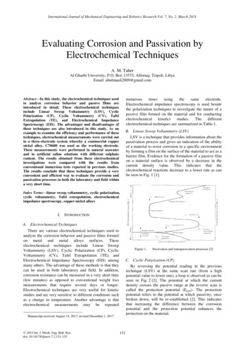
Int. J. Electrochem. Sci., Vol. 14, 20194146and finally polished with 1.0 and 0.5 μm alumina polishing powder, rinsed, ultrasonically degreasedwith alcohol and dried in warm air.Electrochemical measurements were performed in (a) 3.5% sodium chloride and (b) 3.5%sodium chloride 0.05 M sodium thiosulfate solutions at room temperature. The test solutions werefreshly prepared with distilled water for each electrochemical measurement. All measurements were runusing a Princeton VersaSTAT 3 electrochemical system, which comprised a traditional corrosion cellwith a three-electrode system. A saturated calomel reference electrode (SCE) was connected to the cellvia a Luggin capillary filled with a salt bridge as reference electrode and a platinum plate was used as acounter electrode.At the beginning of each electrochemical measurement, the specimens were pretreated with acathodic reduction process at -0.8 VSCE for 30 minutes to remove the oxide film. The specimen wasthen able to corrode freely for 30 minutes and obtain a stable open circuit potential (OCP) for all tests.The potentiodynamic polarization curves started at -0.8 VSCE to the transpassive potential and wererecorded at a rate of 0.5 mV s-1. EIS tests were performed at a steady state OCP and varied from 100kHz to 10 mHz, with a frequency of 10 points per decade and at an amplitude of 10 mV ac as a sinefunction. ZView software was used for the measured EIS data analysis. Mott-Schottky measurementswere scanned from -0.8VSCE to 1.2VSCE in the anodic direction at a step height of 15 mV and a frequencyof 1 kHz. All the electrochemical measurements were repeated three times on separate specimens atroom temperature (25 ).The chemical analysis of the passive films after potentiostatic polarization at different potentialsfor 8 hours was performed by XPS using a Thermo ESCALAB 250XI spectrometer with a pass energyof 20 eV and a monochromatic Al Kα radiation source. The spectrum fitting was performed usingXPSPEAK software which contains the Shirley background subtraction and Gaussian-Lorentzian tailfunction.The composition of the gases produced during the corrosion process was measured by a massspectrometer Pfeiffer Vacuum QMS 220. When a steady state anodic dissolution was obtained, the massspectrometer was connected to the reaction to detect the composition of the gas prior to platform. Theelectrochemical experiment potential of the corrosion behavior selected for analysis was determinedbased on the potentiodynamic polarization curve.3. RESULTS AND DISCUSSION3.1. Polarization MeasurementsA comparative plot of the potentiodynamic polarization curves for 3.5% NaCl solution with andwithout thiosulfate are shown in Figure 1, revealing multiple steps dissolution, prepassive, passive andtranspassive. No significant differences were observed in the shape of the plots, suggesting that thekinetics of the corrosion processes are not substantially affected. It is clear that thiosulfate alone did notcause severe corrosion; however, the chloride caused the pitting potential to shift slightly toward the
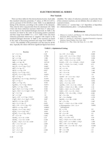
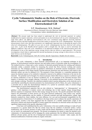
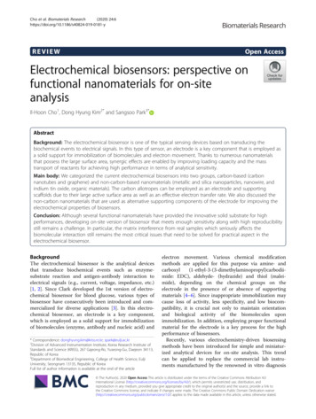
Int. J. Electrochem. Sci., Vol. 14, 20194147negative direction, showing that S2 O2 3 had a detrimental effect on the passive film breakdown and madeit easier for Cl to initiate pitting in the chloride-thiosulfate environment.The morphology of the pitting in the specimens after the polarization measurements in thechloride and thiosulfate solution was different from that in chloride-only solution, as shown in Figure 2and Figure 3. The number of pits in the thiosulfate containing solution was greater than that in thechloride-only solution, and the pits were typically deep and large in diameter. A possible explanation forthis is that thiosulfate accelerated corrosion in pits that were already initiated, leading to rapid pittingpropagation. Thiosulfate and chloride had a synergistic effect on the initiation of pitting corrosion. Inaddition, it should be noted that pits were found in the ferrite phase and at the ferrite side of the ferriteaustenite boundary, as demonstrated in Figure 4.Figure 1. Potentiodynamic polarization of 2205 duplex stainless steel in (a) 0.05 M Na2 S2 O3 , (b) 3.5%NaCl, and (c) 3.5% NaCl 0.05 M Na2 S2 O3 .Figure 2. Corrosion morphology of 2205 duplex stainless steel after potentiodynamic measurements in(a) 3.5% NaCl and (b) 3.5% NaCl 0.05 M Na2 S2 O3 solution.
Int. J. Electrochem. Sci., Vol. 14, 20194148Figure 3. 3D visualization of pits on 2205 duplex stainless steel after potentiodynamic measurements in(a) 3.5% NaCl and (b) 3.5% NaCl 0.05 M Na2 S2 O3 solution.Figure 4. Images of pits on 2205 duplex stainless steel after potentiodynamic measurements in 3.5%NaCl 0.05 M Na2 S2 O3 solution.The selective dissolution of the ferrite phase was attributed to the higher corrosion resistance ofaustenitic phase due to the enrichment of N and Ni [24]. Selective dissolution of the ferrite phase in 2205duplex stainless steel was reported in 10 wt.% FeCl3 solution, and the phenomenon was argued to bedue to the difference in chemical composition between the two phases. The differences in the austeniteand ferrite phases might be affected by the presence of Cu in the austenite phase which can enhance thepitting resistance of the austenitic phase. In addition, the high levels of sulfur in the ferrite phase mayreduce the pitting resistance. Similarly, the presence of phosphorus which is higher in the ferrite phasethan in the austenite is also believed to have a detrimental effect. Therefore, this synergy betweenelements accounts for the improved pitting resistance of the austenite phase.
Int. J. Electrochem. Sci., Vol. 14, 20194149It can be clearly seen that H2S was generated during the dissolution process at a high anodicpotential, and even though it was limited, its generation indicated that the thiosulfate ion was reduced tohydrogen sulfide which would catalyze the anodic dissolution of the duplex stainless steel. Theaggressive Cl- ions in the solution attacked the passive films at high anodic potential, causing oxide filmbreakdown and metastable pitting initiation. Once the films were broken down, the adsorbed S2 O2 3 ionson the fresh bare metal surface could form FeS. The sequence is explained as follows [25-27]. At firstS2 O2 3 was oxidized to form S: S2 O2 (1)3 6H 4e 2S 3H2 OS2 O2 3 might also undergo a disproportionate reaction: S2 O2 (2)3 H S HSO3 The formed S incorporated with H by the following reaction:S 2H 2e H2 S(3)The formed H2S eventually reacted accordingly:nM n 2 H2 S MSn 2 nH (4)where Mn are the Fe, Cr or Ni ions that were dissolved by Cl- pitting corrosion. On the one hand,this corrosion product, was cathodic to stainless steel, causing galvanic coupling corrosion, catalyzingthe anodic dissolution and thus facilitating the corrosion process. On the other hand, the subsequentadsorption and electrochemical reduction resulted in blocking or retarding the passivation orrepassivation and stabilizing the metastable pitting on the 2205 duplex stainless steel [28].3.2. Electrochemical Impedance SpectroscopyFigure 5. Nyquist plots of passive films for 2205 duplex stainless steel polarization at various formationpotentials for 2 hours in 3.5% NaCl 0.05 M Na2 S2 O3 solution.
Int. J. Electrochem. Sci., Vol. 14, 20194150Figure 6. Equivalent circuit for the bilayer oxide film on 2205 duplex stainless steel in 3.5% NaCl 0.05 M Na2 S2 O3 solution.The electrochemical characteristics were measured by EIS to investigate the relative stability ofthe passive film on the 2205 duplex stainless steel. Figure 5 displays the typical Nyquist plots determinedfor 2205 stainless steel in 3.5% sodium chloride 0.05 M sodium thiosulfate solution after immersionin an applied potential for 2 hours at room temperature. It is interesting to note that the impedance arcradius increased at first and then decreased with polarization potential. This trend revealed that thesolution containing Cl- and S2 O2 3 slightly deteriorated the passive films in the passive region at highanodic potentials and contributed to the detrimental effect of the thiosulfate [29]. Thiosulfate ionsappeared to influence the passivation behavior in a complicated manner.Thiosulfate ions have been reported as potentially detrimental to the stability of passive films[30]. This differs from the reported results for the passive film on 2205 duplex stainless steel in sodiumthiosulfate solution [31]. This is most likely due to the intricate interaction of Cl- and S2 O2 3 . Theimpedance had the highest value at 0.2 VSCE, revealing excellent passive film resistance and protectivebehavior in the solution [32-34]. However, when the anodic potential was above 0.2 VSCE, the oxidedissolution acceleration is observed even though the specimen is in a well-passivated state.To reveal the impedance response of corrosion in 3.5% sodium chloride 0.05M sodiumthiosulfate environment, an electrical equivalent circuit with two time constant phase elements,R1(CPE1) and R2(CPE2), were proposed to account for the electrochemical behavior and determinequantitative aspects of the electrolyte/sample interface. Yoon and Lee [35] suggested that the corrosionresistance of the passive film decreased with the increasing of doping concentration. The CPE is definedin an impedance representation as follows:Zω Z (jω) n(5)
Int. J. Electrochem. Sci., Vol. 14, 20194151where Z is the CPE constant, ω is the angular frequency, j2 -1 is the imaginary number and nis the CPE exponent. The factor n is an adjustable parameter that ranges from 0 to 1. CPE can representresistance (n 0, Z R), capacitance (n 1, Z C), or Warburg impedance (n 0.5, Z W).The appropriate equivalent circuit is shown in Figure 6. Therefore, the physical interpretationused in the present study was as follows. Rs is the solution resistance and the high frequency timeconstant R1(CPE1) is correlated with the areas covered with the passive film and is represented by thepassive film admittance CPE1 and the passive layer resistance R1. The low frequency time constantR2(CPE2) is assigned to the active surface area, which is represented by the charge transfer resistance R2and the admittance associated with the double layer capacitance in the active areas [36].The resistance curves as a function of potential are shown in Figure 7. After the values werededuced, C was calculated from Q using the following equation [37]:C (QR)1/nR(6)where R is the resistance of the passive film, Q is a constant phase element, and n is the index ofQ. Then, C can be applied to estimate the thickness of the passive films, which is effective for the parallelplate capacitor model. The thickness of the passive layer was measured with impedance at the formationusing the following relation [38]:ε ε Ad C0(7)where d is the passive layer thickness, ε is the dielectric constant with a usual value of 15.6 forstainless steel, ε0 is the vacuum permittivity (8.85 10-14 F cm-1), A is the valid area of specimen and Cis the capacitance of passive film.Figure 7. Resistance values of the passive film R1 as a function of potential.However, accurate values of the passive film thickness are difficult to obtain via capacitanceanalysis because the dielectric constant ε is generally not well known and may vary with the chemical
Int. J. Electrochem. Sci., Vol. 14, 20194152composition of the passive films. The estimated values of passive film thickness in the chloridethiosulfate solution at different potentials were shown in Table 2. The values of d, which were estimated,indicate that the films formed are generally a few nanometers thick at different formation potentials,reaching a maximum thickness of 2.83 nm at 0.2 VSCE formed potential in the chloride-thiosulfateenvironment. This phenomenon is different from the results reported in the literature [31], which suggestthat the values of a passive film thickness are proportional to the applied potentials within the wholepassive region in the Na2S2O3 solution. The phase angle in the low frequency region in the Bode diagram(not shown) decreased with increasing applied potential, indicating degradation of the passive film.Accordingly, it can be deduced that chloride and thiosulfate synergistically deteriorate the passive filmslightly at high anodic potentials even in the passive region. It has been recognized that the detrimentaleffects of thiosulfate in chloride solutions depend on the electrode potential [39].Table 2. The estimated values of passive film thickness on 2205 duplex stainless steel in the chloridethiosulfate solution at different potentials.Potential (SCE)-0.600.200.60Thickness (nm)0.80 0.092.83 0.131.44 0.113.3. Capacitance MeasurementsThe semiconductor characteristics of the passive films on 2205 duplex stainless steel formed inchloride solution containing thiosulfate at different potentials were investigated by electrochemicalcapacitance measurements. The relationship between capacitance behavior and the applied potential isprovided by the classical Mott-Schottky theory, which indicates the potential dependence of the spacecharge capacitance, C, of a semiconductor electrode under depletion conditions [40]:12kT ε ε e N (E EFB e )(8)C20where the positive slope indicates an n-type semiconductor and negative slope indicates a p-typesemiconductor, ε is the relative dielectric constant of the passive film that has a usual value of 15.6 forstainless steel, ε0 is the vacuum permittivity with a value of 8.854 10-14 F cm-1, e is the electron chargewith a value of 1.6 10-19 C, N is charge carrier density, NA is the electron donor density for an n-typesemiconductor, ND is the acceptor density for a p-type semiconductor, k is the Boltzmann constant witha value of 1.38 10-23 J K-1, and T is the absolute temperature (K), E is the electrode applied potentialand EFB is the flatband potential. The donor density can be calculated from the slope of the linear plot C2vs E, and the flatband potential can be derived from extrapolation to C 0. The interfacial capacitanceC is acquired according to Sikora and Macdonald:1C ω Z(9)iwhere ω 2πf is the angular frequency and Zi is the imaginary component of the impedance.Figure 8 displays the Mott-Schottky plots of the films on 2205 duplex stainless steel formed in3.5% sodium chloride 0.05 M sodium thiosulfate solution at different forming potentials. For duplex
Int. J. Electrochem. Sci., Vol. 14, 20194153stainless steels, it is supposed that the semiconductor properties exhibit the duplex character of thesurface films, with an inner region mainly formed by Cr2O3 and an outer virtually consisting of Fe2O3.In the case where films on 2205 duplex stainless steel formed at various formation potentials, the plotsC-2 vs. E (the applied potential) reveal the presence of four regions where a Mott-Schottky-type propertycan be detected.Figure 8. Mott-Schottky approach for film formed on 2205 duplex stainless steel in 3.5% NaCl 0.05M Na2 S2 O3 solution passivated at different potentials for 2 hours.The first region, for potentials between -0.50 VSCE and 0.25 VSCE, is characteristic of n-typesemiconductors with a positive slope. The negative slopes indicate a p-type semiconductor at a potentialfrom 0.25 VSCE to 0.6 VSCE. The flat band potentials (EFB) indicated the redox potentials of theelectroactive ions in the electrolyte. The repeated variation of n-type to p-type occurs at potentials from0.6 VSCE to 0.85 VSCE and 0.85 VSCE to 1.0 VSCE. This trend is possibly caused by the structure andcomposition of the passive films on stainless steel. Based on the polarization curve shown in Figure 1,it is generally understood that the semiconductor behavior reflects the bipolar character of the surfacefilms for stainless steels and other Fe-Cr alloy materials. Additionally, it is worth noting that a fluctuationof the slopes occurred at approximately 0.4 VSCE, which may be attributed to the dissolution of Cr oxides,where Cr(III) oxidized to form Cr(VI).The values of donor density ND can be calculated from the slope of the C-2 vs. E data assuminga dielectric constant of the passive film on the stainless steel [39]. The calculated ND for the films on2205 duplex stainless steel formed at various potentials in chloride solution containing thiosulfate aredisplayed in Table 3.
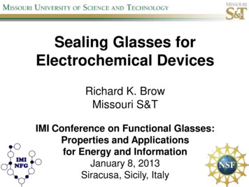
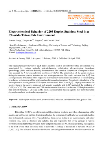
Int. J. Electrochem. Sci., Vol. 14, 20194154Table 3 Effect of passive potential on semiconducting properties of the films formed on duplex stainlesssteel in chloride-thiosulfate solution.E/VSCENd (1021cm-3)EFB (V/SCE)-0.605.49 0.26-0.62 0.080.001.82 0.38-0.53 0.030.151.17 0.19-0.54 0.060.200.98 0.13-0.55 0.030.251.07 0.27-0.50 0.070.605.12 0.15-0.42 0.05According to equation (8), the slopes of the linear portion of the C-2 vs. E plot provide the chargecarrier density N according to the relation:2N e m ε ε(10)0where e is the electron charge, m is the slope of the Mott-Schottky plot in the linear portion, ε0 isthe vacuum permittivity, and ε is the relative dielectric constant of the semiconductor.The point defect model (PDM) presumes that the cation interstitials and oxygen vacancies aregenerated at the metal/film interface, whereas cation vacancies are generated at the film/electrolyteinterface [40]. In the PDM, the donor density ND characterizes the dissolution cation vacancyconcentration at the film/electrolyte interface. Therefore, the increase in ND is related to the increaseddissolution rate of the passive film, and the maximum value of doping density in the passive film isrelated to the worst corrosion resistance [34]. In other words, the film becomes thinner and reveals thatthe corrosion resistance of the passive layer is weakened. The EFB, which determines the position ofenergy bands, is related to the redox potentials of electroactive ions in the electrolyte. The changes inEFB are complicated and affected by various factors. As the polarization formation potential reached 0.6VSCE, EFB sharply increased from -0.6 VSCE to approximately -0.4 VSCE. Tsuchiya and Cunha Belo [41]proposed that the results can be attributed to the transformed inner oxides.3.4. XPS Analysis of Passive FilmsThe chemical composition may have a great effect on the stability and semiconductorcharacteristics of the passive film on steels. There are three different regions of anodic polarization withdifferent electrochemical reactions and dynamic characteristics, causing different chemical compositionsof the passive films. XPS measurements were done to analyze the chemical composition of passive filmsformed on specimens after electrochemical polarization at different potentials for 8 hours directly.Figures 9-12 illustrate the high-resolution spectra of Fe 2p3/2, Cr 2p3/2, Ni 2p3/2 and O 1s of the passive
Int. J. Electrochem. Sci., Vol. 14, 20194155films. These results reveal that the primary components of the passive films on 2205 duplex stainlesssteel in the chloride-thiosulfate solutions were Cr oxide and Fe oxide. After background subtractionaccording to Shirley [42], the XPS analyses were divided into different oxidation states by a fittingprocedure that was studied in a previous study [40].Figure 9. The XPS spectra of Cr 2p3/2 of the passive film formed on 2205 duplex stainless steel surfaceafter passivation at -0.6 VSCE, 0.2 VSCE, 0.6 VSCE.Figure 10. The XPS spectra of Fe 2p3/2 of the passive film formed on 2205 duplex stainless steel surfaceafter passivation at -0.6 VSCE, 0.2 VSCE, 0.6 VSCE.
Int. J. Electrochem. Sci., Vol. 14, 20194156Figure 11. The XPS spectra of Ni 2p3/2 of the passive film formed on 2205 duplex stainless steel surfaceafter passivation at -0.6 VSCE, 0.2 VSCE, 0.6 VSCE.Figure 12. The XPS spectra of O 1s of the passive film formed on 2205 duplex stainless steel surfaceafter passivation at -0.6 VSCE, 0.2 VSCE, 0.6 VSCE.
Int. J. Electrochem. Sci., Vol. 14, 20194157Figure 13. Evolution of Cr2O3 and Fe2O3 in the passive film formed on 2205 duplex stainless steel as afunction of potential in 3.5% NaCl 0.05 M Na2 S2 O3 solution.According to binding energies, the chromium profile revealed that there are mainly threeconstituent peaks representing the metallic state: Cr0 (574.3 eV), Cr2O3 (576.3 eV) and Cr(OH)3 (577.1eV). The oxide species are the primary chemical component of the passive films on the stainless steel.The chromium in the oxide layer plays an important role in the corrosion resistance and theelectrochemical behavior of the passive films. The spectra of Fe 2p3/2 show several constituent peakscorresponding to the metallic Fe0 (707.7 eV), Fe2 and Fe3 species. The relative peaks of FeO (709.4eV) and Fe2O3 (710.9 eV) indicate that the Fe2 and Fe3 species were in the iron oxide in the passivefilms. Ni 2p3/2 spectra represented the metallic state Ni0 (852.8 eV), NiO (854.3 eV) and Ni(OH)2 (855.6eV). The oxygen species, O2- and OH-, of the passive film act as metal ion connections. The O 1s signalindicated three different components as well. The peak at 530.2 eV was a result of an anhydrous oxidespecies, M-O (M being the alloy), whereas the peak at 531.8 eV was characteristic of the hydrated oxidespecies, M-OH. The final peak at 533 eV was due to residual water on the specimen surface.Additionally, the spectra for S 2p were also scanned, but no obvious peaks were detected in the passivefilms.The applied passive potential increased from 0.2VSCE to 0.6VSCE leading to an increase in thecontent of metallic Fe and metallic Cr. The increasing metallic content revealed that the thickness of thepassive film decreased due to the detrimental effect of thiosulfate. From the spectra of the passive filmsin the tested solution at 0.6 VSCE, a sufficient overpotential existed for chromium oxidation anddissolution, and the ratio of Fe2O3 to Cr2O3 in the passive film increased as the polarization potentialincreased, as shown in Figure 13. The values were normalized based on the composition of the surveysan. The critical potential indicates the boundary between two types of passive films. At low potential,a Cr-rich passive film protected the surface, whereas above 0.2 VSCE, Cr(III) oxidized to Cr(VI) anddissolved into the solution.
Int. J. Electrochem. Sci., Vol. 14, 20194158From thermodynamic considerations, when the potential was higher than 0.2 VSCE, the outerpassive film on 2205 duplex stainless steel was strongly affected by the applied formation potential, andthe main carrier concentration increased rapidly with increasing formation potential. For the inner oxidelayer, Cr(III) was initially oxidized to Cr(VI) and strongly dissolved at a higher potential, resulting inthe reduction of Cr2O3 in the film, which was important for the corrosion resistance of the stainless steel.The deterioration of the passive film caused by the dissolution can be observed by the decrease ofimpedance and the increase of ND. Figure 14 showed the schematic of the electrochemical behavior of2205 duplex stainless steel in chloride-thiosulfate environment. In summary, the passivation process wasdynamic rather than static; that is, the passive film was growing and dissolving simultaneously. In thepassive state, both oxide formation and dissolution processes occurred on the specimen surface. Theformer thickens the passive film, whereas the latter leads to a reduction of the film thickness. When thepassivation potential was higher than 0.2 VSCE, the dissolution rate of the passive film was greater thanthe growth rate, the film became thinner, and the protection became worse. As the potentials continuedto increase, the dissolution rate increased.Figure 14. Schematic of the electrochemical behaviour of 2205 duplex stainless steel in chloridethiosulfate environment.
Int. J. Electrochem. Sci., Vol. 14, 201941594. CONCLUSIONSThe electrochemical behavior of 2205 duplex stainless steel in 3.5% chloride solutionscontaining 0.05 M thiosulfate was investigated using potentiodynamic polarization, EIS, Mott-Schottkyand XPS measurements. The main conclusions obtained are presented below:The polarization results show that S2 O2 3 played a detrimental effect on pitting potential in thechloride containing 0.05 M thiosulfate solution. H2S generated during the dissolution process at highanodic potential was detected indicating that the thiosulfate ion was reduced to hydrogen sulfide, whichcatalyzed anodic dissolution once the films were broken down. The selective dissolution of the ferritephase was
The surface morphology was observed by a digital microscope KEYENCE VHX-5000 with a visible 3D microscopy system and scanning electron microscopy (SEM). A mass spectrometer was used to detect the composition of the gases produced during the corrosion process. 2. MATERIALS AND METHODS