Transcription
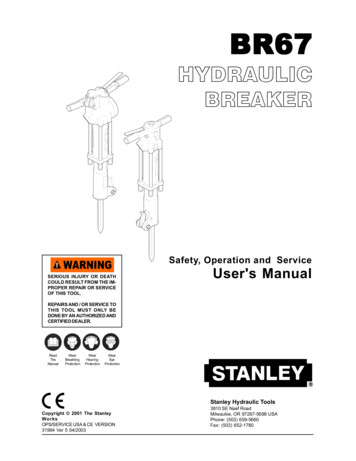
BR67HYDRAULICBREAKERSafety, Operation and ServiceSERIOUS INJURY OR DEATHCOULD RESULT FROM THE IMPROPER REPAIR OR SERVICEOF THIS TOOL.User's ManualREPAIRS AND / OR SERVICE TOTHIS TOOL MUST ONLY BEDONE BY AN AUTHORIZED ANDCERTIFIED ringProtectionWearEyeProtectionStanley Hydraulic ToolsCopyright 2001 The StanleyWorksOPS/SERVICE USA & CE VERSION31994 Ver 5 04/20033810 SE Naef RoadMilwaukie, OR 97267-5698 USAPhone: (503) 659-5660Fax: (503) 652-1780
TABLE OF CONTENTSContents . 1Certificate of Conformity . 2Safety Precautions . 3 - 4Tool Stickers and Tags . 5 - 6Hydraulic Hose Requirements . 7Hydraulic System Requirements . 8Equipment Protection and Care . 9Operation . 10Service . 11-16Accumulator Charging . 17Troubleshooting . 18Specifications . 19Accessories . 19Special Tools . 19Parts Lists . 20Parts Illustration for Standard Handle Models . 21Parts Illustration for Anti-Vibration Handle Models . 22Warranty . 23SERVICING BR67 BREAKERS: This manual contains safety, operation, Service and routine maintenance instructions. Stanley Hydraulic Tools recommends that servicing of hydraulic tools, otherthan routine maintenance, must be performed by an authorized and certified dealer. Please readthe following warning.SERIOUS INJURY OR DEATH COULD RESULT FROM THE IMPROPER REPAIR OR SERVICE OF THIS TOOL.REPAIRS AND / OR SERVICE TO THIS TOOL MUST ONLY BEDONE BY AN AUTHORIZED AND CERTIFIED DEALER.For the nearest authorized and certified dealer, call Stanley Hydraulic Tools at one of the numbers listed on the back of this manual and ask for a Customer Service Representative.1
CERTIFICATE OF CONFORMITYI, the undersigned:Hydraulic ToolsWinterling, DavidSurname and First namesHereby certify that the construction plant or equipment specified hereunder:1. Manufacturer: Stanley Hydraulic Tools, 3810 Naef Road, Milwaukie, Oregon USA2. Representative in the Union: Stanley Svenska AB, Box 9054, 400 92 Göteborg, SWEDEN3. Category: Hydraulic Hand Held Concrete Breaker4. Make: Stanley Hydraulic Tools5. Type: BR6713801, BR6717201, BR6717202, BR67178016. Type serial number of equipment: All7. Year of manufacture: Beginning 2002Has been manufactured in conformity with the provisions of the Machinery Directive 98/37/ECHarmonized standard applied: EN 792-4We also declare that it meets the specification of Noise Directive 2000/14/EC, measured in accordance tothe Conformity Evaluation Method set out in Annex VI para. 5 and evaluated during production as in AnnexVI para. 6, 2 nd procedure.8. Noise related value: 31 kg9. Measured sound power on equipment representative of this type: 107 LwA10. Guaranteed sound power level for this equipment: 112 LwA11. Notified body for EC directive 2000/14/EC: 0404SMP Svensk Maskinprovning ABFyrisborgsgatan 3754 50 Uppsala, SWEDEN12. Special Provisions: NoneIssued at Stanley Hydraulic Tools, Milwaukie, Oregon USADate: 8/21/02SignaturePosition: Engineering ManagerP/N 52574 Rev.1, 8/21/022
SAFETY SYMBOLSSafety symbols and signal words, as shown below, are used to emphasize all operator, maintenance andrepair actions which, if not strictly followed, could result in a life-threatening situation, bodily injury ordamage to equipment.This is the safety alert symbol. It is used to alert you to potential personal injury hazards. Obey all safety messages that follow this symbolto avoid possible injury or death.This safety alert and signal word indicate an imminently hazardoussituation which, if not avoided, will result in death or serious injury.This safety alert and signal word indicate a potentially hazardoussituation which, if not avoided, could result in death or serious injury.This safety alert and signal word indicate a potentially hazardoussituation which, if not avoided, may result in minor or moderate injury.This signal word indicates a potentially hazardous situation which, ifnot avoided, may result in property damage.This signal word indicates a situation which, if not avoided, will resultin damage to the equipment.IMPORTANTThis signal word indicates a situation which, if not avoided, may resultin damage to the equipment.Always observe safety symbols. They are included for your safety and for the protection of the tool.SOME HYDRAULIC FLUIDS ARE FLAMMABLE, NEVER ALLOW THESEHYDRAULIC FLUIDS TO COME IN CONTACT WITH AN OPEN FLAME.IF A HOSE WERE TO BURST OR IF A TOOL LEAK OCCURS NEXT TOAN OPEN FLAME, THESE HYDRAULIC FLUIDS WILL IGNITE ANDCOULD RESULT IN SERIOUS INJURY OR DEATH.LOCAL SAFETY REGULATIONSEnter any local safety regulations here. Keep these instructions in an area accessible to the operator andmaintenance personnel.3
SAFETY PRECAUTIONSTool operators and maintenance personnel must always comply with the safetyprecautions given in this manual and on the stickers and tags attached to thetool and hose.These safety precautions are given for your safety. Review them carefully beforeoperating the tool and before performing general maintenance or repairs.Supervising personnel should develop additional precautions relating to thespecific work area and local safety regulations. If so, place the added precautions in the space provided on page 3.This tool will provide safe and dependable service if operated in accordance with the instructions given in this manual. Read andunderstand this manual and any stickers and tags attached to the tool and hoses before operation. Failure to do so could result inpersonal injury or equipment damage.Operator must start in a work area without bystanders. The operator must be familiar with all prohibitedwork areas such as excessive slopes and dangerous terrain conditions.Establish a training program for all operators to ensure safe operations.Do not operate the tool unless thoroughly trained or under the supervision of an instructor.Always wear safety equipment such as goggles, head protection, and safety shoes at all times whenoperating the tool.Do not inspect or clean the tool while the hydraulic power source is connected. Accidental engagement ofthe tool can cause serious injury.Do not operate this tool without first reading the Operating Instructions.Do not install or remove this tool while the hydraulic power source is connected. Accidental engagementof the tool can cause serious injury.Never operate the tool if you cannot be sure that underground utilities are not present. Undergroundelectrical utilities present an electrocution hazard. Underground gas utilities present an explosion hazard.Other underground utilities may present other hazards.Do not wear loose fitting clothing when operating the tool. Loose fitting clothing can get entangled withthe tool and cause serious injury.Supply hoses must have a minimum working pressure rating of 2500 psi/175 bar.Check fastener tightness often and before each use daily, also make sure all hose connections are tight.The hydraulic circuit control valve must be in the “OFF” position when coupling or uncoupling the tool.Wipe all couplers clean before connecting. Failure to do so may result in damage to the quick couplersand cause overheating. Use only lint-free cloths.Do not operate the tool at oil temperatures above 140 F/60 C. Operation at higher oil temperatures cancause operator discomfort and may cause damage to the tool.Do not operate a damaged, improperly adjusted, or incompletely assembled tool.To avoid personal injury or equipment damage, all tool repair, maintenance and service must only beperformed by authorized and properly trained personnel.Do not exceed the rated limits of the tool or use the tool for applications beyond its design capacity.Always keep critical tool markings, such as labels and warning stickers legible.Always replace parts with replacement parts recommended by Stanley Hydraulic Tools.4
TOOL STICKERS & TAGSSERIAL NO. STAMPING11207 CIRCUIT "D" STICKER(CE Models Only)58604 GUARANTEED SOUNDPOWER LEVEL STICKER (CE Models Only)12542 NAME TAGSERIAL NO. STAMPING28322 CE LABEL(CE Models Only)28322 CE LABEL (CE Models Only)11207 CIRCUIT "D" STICKER(CE Models Only)58604 GUARANTEED SOUNDPOWER LEVEL STICKER(CE Models Only)28409 COMPOSITE STICKER(CE Models Only)28409 COMPOSITE STICKER(CE Models Only)28380 MODEL STICKER(CE Models Only)28376 NAME TAG (CE Models Only)or 12542 NAME TAG11208 SHANK LENGTH STICKER(UK Models Only)D A N G E RD A N G E R1. FAILURE TO USE HYDRAULIC HOSE LABELED AND CERTIFIEDAS NON-CONDUCTIVE WHEN USING HYDRAULIC TOOLS ONOR NEAR ELECTRICAL LINES MAY RESULT IN DEATH OR SERIOUS INJURY.BEFORE USING HOSE LABELED AND CERTIFIED AS NON-CONDUCTIVE ON OR NEAR ELECTRIC LINES BE SURE THE HOSE ISMAINTAINED AS NON-CONDUCTIVE. THE HOSE SHOULD BEREGULARLY TESTED FOR ELECTRIC CURRENT LEAKAGE INACCORDANCE WITH YOUR SAFETY DEPARTMENT INSTRUCTIONS.2. A HYDRAULIC LEAK OR BURST MAY CAUSE OIL INJECTIONINTO THE BODY OR CAUSE OTHER SEVERE PERSONAL INJURY.The safety tag (p/n 15875)at right is attached to thetool when shipped from thefactory. Read and understand the safety instructions listed on this tagbefore removal. Wesuggest you retain this tagand attach it to the toolwhen not in use.ADO NOT EXCEED SPECIFIED FLOW AND PRESSURE FORTHIS TOOL. EXCESS FLOW OR PRESSURE MAY CAUSE ALEAK OR BURST.BDO NOT EXCEED RATED WORKING PRESSURE OF HYDRAULIC HOSE USED WITH THIS TOOL. EXCESS PRESSURE MAYCAUSE A LEAK OR BURST.C CHECK TOOL HOSE COUPLERS AND CONNECTORS DAILYFOR LEAKS. DO NOT FEEL FOR LEAKS WITH YOUR HANDS.CONTACT WITH A LEAK MAY RESULT IN SEVERE PERSONALINJURY.D DO NOT LIFT OR CARRY TOOL BY THE HOSES. DO NOTABUSE HOSE. DO NOT USE KINKED, TORN OR DAMAGEDHOSE.3. MAKE SURE HYDRAULIC HOSES ARE PROPERLY CONNECTEDTO THE TOOL BEFORE PRESSURING SYSTEM. SYSTEM PRESSURE HOSE MUST ALWAYS BE CONNECTED TO TOOL "IN" PORT.SYSTEM RETURN HOSE MUST ALWAYS BE CONNECTED TO TOOL"OUT" PORT. REVERSING CONNECTIONS MAY CAUSE REVERSETOOL OPERATION WHICH CAN RESULT IN SEVERE PERSONALINJURY.4. DO NOT CONNECT OPEN-CENTER TOOLS TO CLOSED-CENTERHYDRAULIC SYSTEMS. THIS MAY RESULT IN LOSS OF OTHERHYDRAULIC FUNCTIONS POWERED BY THE SAME SYSTEM AND/OR SEVERE PERSONAL INJURY.5. BYSTANDERS MAY BE INJURED IN YOUR WORK AREA. KEEP BYSTANDERS CLEAR OF YOUR WORK AREA.6. WEAR HEARING, EYE, FOOT, HAND AND HEAD PROTECTION.7. TO AVOID PERSONAL INJURY OR EQUIPMENT DAMAGE, ALL TOOLREPAIR MAINTENANCE AND SERVICE MUST ONLY BE PERFORMED BY AUTHORIZED AND PROPERLY TRAINED PERSONNEL.I M P O R TA N TI M P O R TA N TREAD OPERATION MANUAL ANDSAFETY INSTRUCTIONS FOR THISTOOL BEFORE USING IT.READ OPERATION MANUAL ANDSAFETY INSTRUCTIONS FOR THISTOOL BEFORE USING IT.USE ONLY PARTS AND REPAIRPROCEDURES APPROVED BYSTANLEY AND DESCRIBED IN THE OPERATIONMANUAL.USE ONLY PARTS AND REPAIRPROCEDURES APPROVED BYSTANLEY AND DESCRIBED IN THE OPERATIONMANUAL.TAG TO BE REMOVED ONLY BYTOOL OPERATOR.TAG TO BE REMOVED ONLY BYTOOL OPERATOR.SEE OTHER SIDE15875SEE OTHER SIDE15875SAFETY TAG P/N 15875 (shown smaller then actual size)5
TOOL STICKERS & TAGSBR67 BREAKERDivision of The Stanley WorksStanley Hydraulic ToolsSERIAL NO.FLOW 7-9 GPM/26-34 LPMPRESS 1500-2000 PSI105-140 BARACCUMULATOR CHG600 PSI/42 BARNITROGENNAME TAG STICKER p/n 12542or p/n 29203(shown smaller than actual size)A name tag sticker is attached to the breaker.Never exceed the flow and pressure levelsspecified on this sticker.The information listed on the name tag stickermust be legible at all times. Replace thissticker if it becomes worn or damaged. A replacement is available from your local Stanleydistributor.CE STICKER p/n 28322(shown approx size)STANLEY LABEL STICKERp/n 28376(shown smaller than actualsize)CIRCUIT "D" STICKERp/n 11207(shown smaller than actual size)GUARANTEED SOUND POWERLEVEL STICKERp/n 58604(shown smaller than actual size)6" 6¼"COMPOSITE STICKERp/n 28409(shown smaller than actual size)MODEL No. LABELp/n 28380(CE Models Only)HEX SHANK STICKER p/n 11208(UK Models Only)6
HYDRAULIC HOSE REQUIREMENTSHOSE TYPESHydraulic hose types authorized for use with Stanley Hydraulic Tools are as follows:1Certified non-conductive2Wire-braided (conductive)3Fabric-braided (not certified or labeled non-conductive)Hose 1 listed above is the only hose authorized for use near electrical conductors.Hoses 2 and 3 listed above are conductive and must never be used near electrical conductors.To help ensure your safety, the following DANGER tags are attached to all hose purchased from StanleyHydraulic Tools. DO NOT REMOVE THESE TAGS.If the information on a tag is illegible because of wear or damage, replace the tag immediately. A new tagmay be obtained at no charge from your Stanley Distributor.1CERTIFIED NON-CONDUCTIVE HOSED A N G E RD A N G E R1 FAILURE TO USE HYDRAULIC HOSE LABELED AND CERTIFIED AS NON-CONDUCTIVE WHENUSING HYDRAULIC TOOLS ON OR NEAR ELECTRIC LINES MAYRESULT IN DEATH OR SERIOUSINJURY.FOR PROPER AND SAFE OPERATION MAKE SURE THAT YOU HAVE BEEN PROPERLY TRAINED INCORRECT PROCEDURES REQUIRED FOR WORK ON OR AROUND ELECTRIC LINES.3. DO NOT EXCEED HOSE WORKING PRESSURE OR ABUSE HOSE. IMPROPER USE OR HANDLINGOF HOSE COULD RESULT IN BURST OR OTHER HOSE FAILURE. KEEP HOSE AS FAR AWAY ASPOSSIBLE FROM BODY AND DO NOT PERMIT DIRECT CONTACT DURING USE. CONTACT AT THEBURST CAN CAUSE BODILY INJECTION AND SEVERE PERSONAL INJURY.2. BEFORE USING HYDRAULIC HOSE LABELED AND CERTIFIED AS NON-CONDUCTIVE ON ORNEAR ELECTRIC LINES. WIPE THE ENTIRE LENGTH OF THE HOSE AND FITTING WITH A CLEANDRY ABSORBENT CLOTH TO REMOVE DIRT AND MOSISTURE AND TEST HOSE FOR MAXIMUMALLOWABLE CURRENT LEAKAGE IN ACCORDANCE WITH SAFETY DEPARTMENTINSTRUCTIONS.4. HANDLE AND ROUTE HOSE CAREFULLY TO AVOID KINKING, ABRASION, CUTTING, OR CONTACTWITH HIGH TEMPERATURE SURFACES. DO NOT USE IF KINKED. DO NOT USE HOSE TO PULL ORLIFT TOOLS, POWER UNITS, ETC.5. CHECK ENTIRE HOSE FOR CUTS CRACKS LEAKS ABRASIONS, BULGES, OR DAMAGE TOCOUPLINGS IF ANY OF THESE CONDITIONS EXIST, REPLACE THE HOSE IMMEDIATELY. NEVERUSE TAPE OR ANY DEVICE TO ATTEMPT TO MEND THE HOSE.DO NOT REMOVE THISTA GDO NOT REMOVE THISTA GThis tag is attached to all certified non-conductive hose.6. AFTER EACH USE STORE IN A CLEAN DRY AREA.SEE OTHER SIDESIDE 1SEE OTHER SIDE(shown smaller than actual size)SIDE 22 AND 1 3WIRE-BRAIDED AND FABRIC-BRAIDED (NOT CERTIFIED OR LABELED NON-CONDUCTIVE) HOSEThis tag is attached to all conductive hose.DO NOT REMOVE THISTA G2. FOR PROPER AND SAFE OPERATION MAKE SURE THAT YOU HAVE BEEN PROPERLY TRAINED INCORRECT PROCEDURES REQUIRED FOR WORK ON OR AROUND ELECTRIC LINES.5. CHECK ENTIRE HOSE FOR CUTS CRACKS LEAKS ABRASIONS, BULGES, OR DAMAGE TOCOUPLINGS IF ANY OF THESE CONDITIONS EXIST, REPLACE THE HOSE IMMEDIATELY. NEVERUSE TAPE OR ANY DEVICE TO ATTEMPT TO MEND THE HOSE.6. AFTER EACH USE STORE IN A CLEAN DRY AREA.3. DO NOT EXCEED HOSE WORKING PRESSURE OR ABUSE HOSE. IMPROPER USE OR HANDLINGOF HOSE COULD RESULT IN BURST OR OTHER HOSE FAILURE. KEEP HOSE AS FAR AWAY ASPOSSIBLE FROM BODY AND DO NOT PERMIT DIRECT CONTACT DURING USE. CONTACT ATTHE BURST CAN CAUSE BODILY INJECTION AND SEVERE PERSONAL INJURY.4. HANDLE AND ROUTE HOSE CAREFULLY TO AVOID KINKING, CUTTING, OR CONTACT WITHHIGH TEMPERATURE SURFACES. DO NOT USE IF KINKED. DO NOT USE HOSE TO PULL OR LIFTTOOLS, POWER UNITS, ETC.DO NOT REMOVE THISTA GD A N G E RD A N G E R1 DO NOT USE THIS HYDRAULIC HOSE IN OR NEAR ELECTRIC LINES. THIS HOSE IS NOT LABELEDOR CERTIFIED AS NON-CONDUCTIVE. USING THIS HOSE ON OR NEAR ELECTRICAL LINES MAYRESULT IN DEATH OR SERIOUS INJURY.SEE OTHER SIDESEE OTHER SIDESIDE 1(shown smaller than actual size)SIDE 2HOSE PRESSURE RATINGThe rated working pressure of the hydraulic hose must be equal or higher than the relief valve setting on thehydraulic system.7
HTMA RequirementsHydraulic SystemRequirementsToolCategory:Flow rateTool Operating Pressure20Lpm at 138barBHTMA CATEGORY30Lpm at 138barBHTMA CATEGORYType IType IIType III4-6 GPM (15-23 lpm)2000 psi (138 bar)7-9 GPM (26-34 lpm)2000 psi (138 bar)11-13 GPM (42-49 lpm)2000 psi (138 bar)(at the power supply outlet)System relief valve setting(at the power supply outlet)Maximum back pressure(at tool end of the return hose)Measured at a max. fluid viscosity of:(at min. operating temperature)TemperatureSufficient heat rejection capacityto limit max. fluid temperature to:(at max. expected ambient temperature)Min. cooling capacityat a temperature difference ofbetween ambient and fluid temps2100-22502100-22502100-2250(145-155 bar)(145-155 bar)(145-155 bar)250 psi250 psi250 psi(17 bar)(17 bar)(17 bar)400 SSU400 SSU400 SSU(82 centistokes)(82 centistokes)(82 centistokes)140 F (60 C)140 F (60 C)140 F (60 C)3 hp (2.24 kW)40 F (22 C)5 hp (3.73 kW)40 F (22 C)7 hp (5.22 kW)40 F (22 C)NOTE: Do not operate the tool at oil temperatures above 140 F (60 C). Operation at higher temperatures can cause operatordiscomfort at the tool.FilterMin. full-flow filtrationsized for flow of at least:25 microns30 GPM (114 lpm)25 microns30 GPM (114 lpm)25 microns30 GPM (114 lpm)(For cold temp. startup and max. dirt-holding capacity)Hydraulic fluidPetroleum based(premium grade, anti-wear, non-conductive)Viscosity(at min. and max. operating temps)100-400 SSU*(20-82 centistokes)100-400 SSU*(20-82 centistokes)100-400 SSU*(20-82 centistokes)NOTE: When choosing hydraulic fluid, the expected oil temperature extremes that will be experienced in service determine themost suitable temperature viscosity characteristics. Hydraulic fluids with a viscosity index over 140 will meet the requirements overa wide range of operating temperatures.*SSU Saybolt Seconds UniversalNOTE: These are general hydraulic system requirements. See tool Specification page fortool specific requirements.8
Equipment Protection and CareIn addition to the SafetyPrecautions on page 3 & 4of this manual, observe thefollowing for equipmentprotection and care. Make sure all couplers are wiped clean before connection. The hydraulic circuit control valve must be in the “OFF” position when coupling or uncouplinghydraulic tools. Failure to do so may result in damage to the quick couples and cause overheatingof the hydraulic system. Always store the tool in a clean dry space, safe from damage or pilferage. Make sure the circuit PRESSURE hose (with male quick disconnect) is connected to the “IN” port.The circuit RETURN hose (with female quick disconnect) is connected to the opposite port. Do notreverse circuit flow. This can cause damage to internal seals. Always replace hoses, couplings and other parts with replacement parts recommended by StanleyHydraulic Tools. Supply hoses must have a minimum working pressure rating of 2500 psi/172 bar. Do not exceed the rated flow (see Specifications) page 19 in the manual for correct flow rate andmodel number. Rapid failure of the internal seals may result. Always keep critical tool markings, such as warning stickers and tags legible. Do not force a small breaker to do the job of a large breaker. Keep tool bit sharp for maximum breaker performance. Make sure that tool bits are not chipped orrounded on the striking end. Never operate a breaker without a tool bit or without holding it against the work surface. This putsexcessive strain on the breaker foot. Tool repair should be performed by experienced personnel only. Make certain that the recommended relief valves are installed in the pressure side of the system. Do not use the tool for applications for which it was not intended.9
OPERATIONPREOPERATIONPROCEDURESPREPARATION FOR INITIALUSEEach unit as shipped has no special unpacking orassembly requirements prior to usage. Inspectionto assure the unit was not damaged in shipping anddoes not contain packing debris is all that isrequired.CHECK HYDRAULIC POWERSOURCE1. Using a calibrated flowmeter and pressuregauge, check that the hydraulic power sourcedevelops a flow of 7-9 gpm/26-34 lpm at 1500-2000psi/105-140 bar.2. Make certain the hydraulic power source isequipped with a relief valve set to open at 2100-2250psi/145-155 bar minimum.3. Check that the hydraulic circuit matches the toolfor open-center (OC) operation.CHECK TOOL1. Make sure all tool accessories are correctlyinstalled. Failure to install tool accessories properlycan result in damage to the tool or personal injury.2. There should be no signs of leaks.CONNECT HOSES1. Wipe all hose couplers with a clean lint-free clothbefore making connections.2. Connect the hoses from the hydraulic powersource to the hose couplers on the breaker. It is agood practice to connect the return hose first anddisconnect it last to minimize or avoid trappedpressure within the breaker.3. Observe flow indicators stamped on hosecouplers to be sure that oil will flow in the properdirection. The female coupler is the inlet coupler.NOTE: The pressure increase in uncoupledhoses left in the sun may result in making themdifficult to connect. When possible, connectthe free ends of operating hoses together.OPERATINGPROCEDURES1. Observe all safety precautions.2. Move the hydraulic circuit control valve to the"ON" position.3. Place the tool bit firmly on the surface to bebroken.4. Squeeze the trigger to start the breaker. Adequate down pressure is very important.NOTE: Partially depressing the trigger allows thetool to operate at a slow speed, making it easy tostart the tool bit into the surface to be broken.3. The tool should be clean, with all fittings andfasteners tight.CHECK TRIGGER MECHANISM1. Check that the trigger operates smoothly and isfree to travel between the "ON" and "OFF" positions.COLD WEATHEROPERATIONIf the breaker is to be used during cold weather,preheat the hydraulic fluid at low engine speed.When using the normally recommended fluids, fluidtemperature should be at or above 50 F/10 C(400 ssu/82 centistokes) before use.10
SERVICE INSTRUCTIONSGood maintenance practices will keep the breaker onthe job and increase its service life.A very important maintenance practice is to keep thehydraulic fluid clean at all times. Contaminatedhydraulic fluid causes rapid wear and/or failure ofinternal parts.Follow the procedures contained in the HYDRAULICSYSTEM REQUIREMENTS section of this manual toensure peak performance from the tool. Never disassemble the breaker unless proper troubleshootingprocedures have isolated the problem to an internalpart. Then, only disassemble it to the extent necessary to replace the defective part. KEEP CONTAMINANTS SUCH AS DIRT AND GRIT AWAY FROMINTERNAL PARTS AT ALL TIMES.3. Remove the valve cap assembly (74) from the top ofthe handle. Loosen the 5/8- inch hex charging valvelock nut 1-1/2 turns. Discharge the accumulator downto approximately 20 psi/1.4 bar.IMPORTANTDo not completely discharge the accumulatorat this time.4. Remove the four side rod nuts (66). Remove thebreaker foot assembly (61 or 87) by tapping the top ofthe flange with a plastic or rubber hammer to drive itfrom the flow sleeve tube (40). Remove the o-ring, rodwiper and cup seal (62, 63 & 65) from the foot usingthe proper o-ring tools to avoid damage to groovedsurfaces.Always determine and correct the cause of theproblem prior to reassembly. Further wear and toolfailure can result if the original cause is not corrected.5. Remove the handle assembly (59) from the flowsleeve assembly (40) by tapping on alternate ends ofthe side rods (46) with a plastic or rubber hammerwhile pulling on the handle.DISASSEMBLYAUTOMATIC VALVE BODY & ACCUMULATORASSEMBLYPRIOR TO DISASSEMBLY Clean the exterior of the tool. Obtain a seal kit to replace all seals exposed duringdisassembly. Note the orientation of seals beforeremoving them. Install new seals in the same positionas original seals.HANDLE & ACCUMULATORDISASSEMBLYStandard Handle ModelsRefer To Illustration 2.1. Secure the breaker in a bench vise, with the “IN”and “OUT” ports up, clamping on the flow sleeve tubebetween the side rods. Soft vise jaws are recommended.2. Remove the pigtail hose assemblies.Note: The breaker is full of fluid and will drip from theports when the hoses are removed.6. If the automatic valve body (56) remains in thehandle assembly, the accumulator assembly andautomatic valve body can be removed by placing a 3/4-inch hex deep socket with a 6-inch/15 cm extensionover the charging valve (21) and tapping the extensionwith a plastic or rubber hammer.Note: Make sure the thin washer (42) between theautomatic valve body and the accumulator chamber(79) is properly located in its counterbore beforedriving the automatic valve body and accumulator outof the handle.7. If the accumulator cylinder (70) remains inside thehandle, it can be removed using the accumulatorcylinder puller (Part Number 05640) which seats onthe inside lower contour of the accumulator cylinder.Use a rod that extends through the charge valve holein the handle and drive out the cylinder by tapping onthe rod or use a slide hammer through the 1/2-inch/12.5 mm hole provided in the puller.8. If the entire accumulator assembly was removed instep 4, discharge the accumulator assembly completely and proceed to step 7.9. To remove the accumulator chamber and diaphragm(51) from the accumulator cylinder, Place11
the assembly on disassembly tools (Part Numbers05508 and 04910). Use a rag in the bottom of the flowsleeve removal tube (Part Number 04910) to protectthe accumulator chamber. Drive the chamber anddiaphragm out by tapping or pushing with an arborpress on the charge valve end while protecting thevalve with a 3/4-inch hex deep socket.10. Squeeze the accumulator diaphragm and slide itoff the charge valve end of the accumulator chamber.3. Remove the handle assembly from the flow sleeveassembly by tapping on alternate ends of the siderods with a plastic or rubber hammer while pulling onthe handle.4. If the automatic valve body (56) remains in thehandle assembly, it can be removed by using aspecial tool (30939 sleeve & 05046 bearing puller).11. Remove the cup seal (43) and back-up washer(37) from the accumulator chamber.5. The spacer is removed by using a 7/8 inch collet(30956 collet) and a bearing puller from the 05064bearing puller kit.12. Secure the accumulator chamber in a vise withsoft jaws to remove the charging valve.6. The sintered filter (33) and o-rings (34) are removedby simply picking them out.IMPORTANTAvoid damage to the counterbore of thechamber.TRIGGER13. Remove the trigger (12) from the handle by drivingout the 1/4-inch/6.4 mm diameter Spirol Pin.ACCUMULATOR7. Clamp the handle assembly in a vice with soft jawsand unscrew the charge valve (21). Make sure theaccumulator has been discharged before removing thecharge valve.8. Unscrew the accumulator plug (52) using specialtool 29135 accumulator plug wrench.VALVE SPOOL9. Lift out the accumulator diaphragm (51).14. Remove the valve spool (7) by driving out two 3/16x 1-3/8 inch/5 mm x 35 mm roll pins (77) and tap theend of the spool. The valve spring (8) will eject thespool from the bore bringing the washer and bushingwith it.15. Remove the valve spool spring by turning thehandle on end.16. Remove the orifice plug (30) from the bottom of thevalve spool bore with a long 1 1/4-inch hex wrench.TRIGGER10. Remove 4 capscrews (9) and lift off the top plate(92).11. Unscrew the two pivot screws (49) and lift out thetwo handles (11 & 13) and four springs (24 & 25).Remove the lever (10) and trigger (12) from the handleby driving out the roll pins (23).VALVE SPOOLHANDLE & ACCUMULATORDISASSEMBLYAnti-Vibration Handle ModelsRefer to Illustration 1.1. Remove the modified plug (20) and discharge theaccumulator completely.2. Remove the four side rod nuts (66). Remove thefoot assembly (61) by tapping the top of the flangewith a plastic or rubber hammer to drive it from theflow sleeve tube (40). Remove the o-ring, rod seal andcup seal (62, 63 & 65) from the foot using the propero-ring tools to avoid damage to grooved surfaces.12. Remove the spirolox retaining ring, then removethe SAE plug (32) located at the bottom of the spoolbore. Pick out the spring (8) and then push the valvespool (7) out.FLOW SLEEVE TUBEDISASSEMBLY1. Follow steps 1 through 3 of the HANDLE ANDACCUMULATOR DISASSEMBLY for STANDARDHANDLES or steps 1 through 3 for ANTI-VIBRATIONHANDLES.2. If the automatic valve body remains in the flowsleeve tube, complete the following steps.12
a. Remove the washer (42) and piston (17).b. Place the split rings (p/n 04908) between theautomatic valve body and flow sleeve tube.c. Place the flow sleeve assembly (with split ringsin place) on the flow sleeve removal tube (p/n
Hereby certify that the construction plant or equipment specified hereunder: 1. Manufacturer: Stanley Hydraulic Tools, 3810 Naef Road, Milwaukie, Oregon USA 2. Representative in the Union: Stanley Svenska AB, Box 9054, 400 92 Göteborg, SWEDEN 3. Category: Hydraulic Hand Held Concrete Breaker 4. Make: Stanley Hydraulic Tools 5.