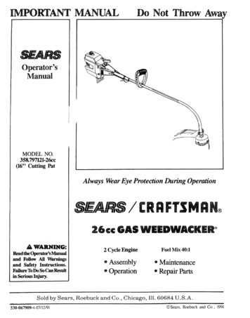
Transcription
IMPORTANT MANUALDo Not Throw Awaii iiHi .ll.,.Operator'sManualMODEL NO.358.797121-26cc(16" CuttingParAlways Wear Eye Protection During Operation26 GAS WEEDWACKERA WARNING:Read the Operator'sManualmd Follow All Warningsand Safety Instructions.ureToDo So Can Resultin Serious I iury.Sold.530-067909-4-07112/91by Sears,Roebuck2 Cycle EngineFuel Mix 40:1 Assemblyo Operationo MaintenanceandCoo, Chicago, Repair PartsIti. 60684U.S.A.N, Sears,Roebuckand Co,1991
ONEYEARLIMITEDWARRANIYON CRAlrl'SMANWEEKWACKER For One Year from dale of archase when this Weedwacke is maintainedlubricated and tuned up according to the operatingand maintenance instructionPs in the operators manual Sears will repair free of charge any defect in rnateria] or workmanshipThis wammlyexcludes nylon line spark plug and a r c eaner" wb ch are expendableparis and become worn during nomlal use.WARRANTY SERVICE IS AVAILABLE BY CONIACTINGIHE NEARESI" SEARS SERVICE CENIER/DEPARIMENIIN THE UNIFED STALES 7his warranty applies only while this product is in ase in the United States'This ' trvant)'gives you specificSEARS,legal rightsROEBUCKand you may also have other rights which vary from state to staleAND CO, DEPTTABLED/731CR-W, SEARSrOWERCHICAGO,.IL 60684.,OF CONTENTS36WARNINGS AND SAFETY INSTRUCTIONSKNOW YOUR TRIMMERASSEMBLY .ACCESSORIF.ENGINE INFORMATIONA Fueling Your EngineB. Pre-Operation ChecksC Starting InstructionsD Operating InstructionsUSING YOUR TRIMMERA Irimmer SafetyB Trimmer Line AdvanceC Cutting MethodsD Line ReplacementGENERAL MAINTENANCE .A Maintenance Safety .71717B Air Filter.17I0C. StarterRope ICK REFERENCE PAGE . 27Flexible Drive Shaft Lubrication .Carburetor Adjustments .Storage .Trouble Shooting Chart .PAR'ISLIST.2326SPEC F ATION"ENGINE''TTPE:i DISP,LACEMENT!ENGINE2-Cycte, Air-Cooled.R M:IGNITION SWITCH26ccOperating ' 7500Idle -- 2800 - 3200I NmON:.SoiidS teCARBURETOR:ENGINE "OFF":Diaphragm All Positions withadjustable fue! mixture jetsPositive SwitchSTARTER:Auto RewindMUFFLER:2bmpemtureLimiting(notspark arresting; see note p,5)CLUTCH:FUEL TANK:17 tL 0Z,'.SPARK pLUG:71-85854 i i4)SPARK,,PLUG GAP:MODULE AIR GAP:.025"SHIELD.010" / .0t4"LUBRICATION:CUTIINGLINE:"SHAFT LEN :(See "Fueling Your'Engine")DS0" Diameter Sears LaserLine " ' MUFFLI48"B --"eNOTE: LASER LINE tS A REGISTERED TRADEMARKOFWHITE CONSOLIDATED INDUSTRIES, INCM'ANUFACI UREDUNDER ONE OR MORE OF tHE FOLLOWINGU.SPATENTS:3 708,967;3 826 068;3 859,776;4 035,912;4,052 789:4,054,992;4 067,108:4, t04,797; 4.114 269;4 1245)38;4,156 31214,156,967;4 161,820;4,167,8 2; 4 269;372;4,286,675; 4 107,901;4. t t2,653; 4 136o446;4,168,572;4,183,138;4,189.833; 4,21 t ,004;4 211 005;4.236,311:4 236 312;4,290,200;4.362,ff/4;4 366,622;4 382,356;4,451,983; 4,483,069; 4.798,185;4,819.742;4,823,465; 4,825 548; 4,835,867; 4,841.929; 4.846,123; 4852.258;DES 249.630 U S AND FOREIGNPATENIS PENDING"SPARK PLUGI'RIMbtFHE.M)
This tool can cause serious injury or blindness to the operator and others. The warnings and safety instructions in this manualmust be followed to provide reasonable safety and efficiency in using this tool, The operator is responsible for following thewarnings and instructions in this manual and on the tool Read the entire Operator's Manual before assembling and usingthis tool! Restrict the use of this power tool to persons who read, understand, and follow the warnings and instructionsin this manual and on the tool.A D GEKNEVER USE BLADESWITH THIS TOOL.-- THE BLADE CAN COME OFF ANDSERIOUSLY INJURE YOU AND OTHERS.-- THIS TOOL IS DESIGNED FORLINE TRIMMER USE ONLY.AW&I IGTHE TRIMMER LINE CAN THROW OBJECTSVIOLENTLYYOU CAN BE BLINDED OR INJURED.-- WEAR EYE AND LEG PROTECTION.HAZARD ZONE FOR THROWN OBJECTS.-- THE TRIMMER LINE CAN THROWOBJECTS VIOLENTLY -- OTHERS CAN BE BLINDEDINJURED.OR-- KEEP PEOPLE AND ANIMALS3O FEET AWAY.READ OPERATOR'S--MANUAL.FOLLOW ALL WARNINGSINSTRUCTIONS.OPERATOR'SMANUALAND
.i,iWARNINGS AND SALTYIIgSTN,ii,iA OPERATOR SAFETY1. Inspectentiretoolbeforeeachuse. Replacedamagedparts.Check for fuel leaks and make sure all fasteners are in placeand securely fastened2 Replace trimmer head parts that a e cracked, chipped,broken, or damaged in any other way before using the tool3 Use only 080" diameter Sears Laser Line Never usewi e. rope. string, etc4 Be sure the shield is properly attached.5. Use only the specified trimmer head See "Specifications."Make sure the trimmer head is properly installed andfastened. Refer to "Assembly"6 Be sure the trimmer head stops turning when engine idtesSee "Carburetor Adjustments."7. Make carburetor adjustrnents with the drive shaft housingsupported to prevent the trimmer line from contacting anyobject Hold the tool by hand; do not use the optionalshoulder strap for support8 Keep others away when making carburetor adjustments.9. Use only accessories or attachments as recommended forthis tool by SearsA FUEL SAt Ir"I "1 Move at least 10 (Let away from fueling site betbre starting engine.2. Use a container approved for fuel.3 Do not smoke or allow smoking near fuel or the tool orwhile using the tool4. Wipe up all fuel spills before starting engine.5 Stop engine before removing fuel cap, Allow the engineto cool before refueling.6. Run fuet out of the rue! system before storing the tool2 Store tool and fuel in an area where fuel vapors cannot reachsparks or open flames from water heaters, electric motorsor switches, furnaces, etc,111ii1,1,,i,iiiii1,1,,,,,,,iCD' t'/NG1 Always wear a safety face shield or safety goggles. See"Accessories"2 Keep hair, fingeIs, and all othet parts of the body awayh'om openings and moving parts Always wear heavy,long pants,, boots, and gloves Do not go barefbot or wearsandals, jewelry, short pants, loose clothing, or clothing with loosely hanging straps, ties. tassels, etc, Securehair so it is above shoulder length Being fully coveredwill help protect you from pieces of toxic p)ants (suchas poison ivy) thrown by the Trinmaer Head, whichcould be more of a hazard than touching the plant itself3. Do not operate this tool when you are tired, ill, or under theinfluence of alcohol, drugs, or medication.4. Always use the assist handle. See "Assembly,"5. Wear hearing protection if you use this tool for more than! V2hours per day.6. Never start or run the engine inside a closed room or building Breathing exhaust fumes can kilt7. Keep handles fi'ee of oil and fuel.& TOOL SAFETY. i, ,i.rr1. Inspect the area to be cut before each use Remove objects(rocks, broken glass, nails, wire, string, etc ) which can bethrown or become entangled in the trimmer head2. Keep others including children, animals, bystanders, andhelper's outside the 60 tbot Hazard Zone Stop the engineimmediately i[ you are approached.3. Always keep the engine on the right side of your body,4 Hold the tool firmly with both hands5. Do not overreach or use from unstable surfaces such asladders, trees, steep slopes, rooftops, etc, Use extra carewhen cleaning on stairways Keep firnafooting and b',danceat all times6 Keep trimmer head below waist level7 Do not raise the engine aboveyour waist The trirrmaer headcan come dangerously elose to your body.8 Keep alt parts ofyour body awayfrom the trimmer head andmuffler when the engine is running9 Useonly forjobs explained in this manual.A MAINTENANCESAFETY1 Maintain the toot according to reco ranended procedures.Keep the trimmer line at the proper length.2 Never start the engine with the clutch shroud removed Theclutch can fly apart and cause serious injury3 Disconnect the spark plug before performing maintenanceexcept for carburetor adjustments.4. Make carburetor adjustments with the drive shaft housingsuppoaed to prevent the trimmer line from contacting anyobject. Hold the toot by hand; do not use the optionalshoulder strap for support5 Keep others away when making carburetor adjustments6. Use only genuine replacement parts as recommendedby Sears T L4 .SPORTL G/ DSTOOGEl Hand carry the tool with theengine stopped and the muffleraway from your body2o Allow the engine to cool, run fuel out ofthe fuel system, andsecure the toot before transporting in a vehicle or storing3. Before storing the tool, use up fuel left in the fuel lines andcarburetor by starting the engine and letting it run until itstops.4. Store tool and fuel in an area where fuel vapors cannot reachsparks or open flames from water heaters, electric motorsor switches, furnaces, etc.5 Store the tool so the line limiter cannot accidenta!ly causeinjury. The tool can be hung by the drive shaft housing orby the bracket below the engine6. Store tool out of reach ofchildren,If situations occur which are not covered in this manual, usecare and good judgement. Contact your Sears ServiceCenter/Depa nent if you need assistance.SAFETY NOTICEExposure to vibrations through prolonged use of gasoline powered hand tools could cause blood vessel or nerve damage in the fingers,hands, and wrists ofpeople prone to circulation disorders or abnormal swellings. Prolonged use in cold weather has been linkedto blood vessel damage in otherwise healthy people. If symptoms occur such as numbness, pain, loss of strength, change in skincolor or texture, or loss of feeling in the fingers, hands, or wrists, discontinue the use of this tool and seek medical attention. Ananti-vibrati on system does not guarantee the avoidance of these problems. Use rs wh o operate power tools on a continual and regular basis must monitor closely their physical condition and the condition of this tool.
KNOW YOUR TRIMMER. 1,11.C. RTONA. ODU 'IONYour Tr'immer is a versatile product designedyou give your lawn a finished appearance.to helpSpecial Features Include: e oCentrifugalClutchAll-Position CarburetorAdjustable, Cushioned Assist HandleSemi-AutomaticLine Feed16"Cutting PathK UNP& GL Remove contentsdone so.KEYNO.123456---ISTRU ON from the canonif you have not2. Check parts against the list below3. ExamfinepartsfordamageDonotusedamagedpans4 Notifi/),our Sears Store immediately ija part is miss'ing cn damagedNOTE: it is normal to hear the fuel fdter rattle in an emptyfue! Drive Shaft Assembly w/Safety LabelShieldTrimmer HeadAssist Handle2-cycle Engine OilOperator's Manual (Not Shown)Loose Parts Bag (Not Shown)* LOOSE PARTS BAG CONTENTS:Flex Shaft LubeScrew - ShieldBracket - ShieldSquared Head Screw - Assist HandleHex Nut - Assist HandleT-Handle - Assist HandleHex Screw - Clutch ShroudHex Nut - Clutch ShroudDust Cup - Drive Shaft HousingHex WrenchHex Screw - Thfottle Trigge HousingHex Nut - Throttle Trigger HousingBracket - Assist HandleI211I122!1IIISAFETY LABEL7SPECIALNOTICEFor users on U.S. Forest Land and in some states, including Cahfornia (Public Resources Codes 4442 and 4443),Idaho, Maine, Minnesota,New Jersey, Oregon, and Washington: Certain internal combustion engines operated onforest, brush, and/or grass-covered land in the above areas are required to be equipped with a spark arrestor, maintainedin effective working order, or the engine must be constructed, equipped, and maintained for the prevention of fire Checkwith your state or local authorities for regulations pertaining to these requirements, Failure to follow these requirementsis a violation of the law. This unit is not factory-equippedwith a spark arrestor;however, a spark arrestor is available as an optional part If a spark arrestor is required in your area, contact your Seres Service Center or Parts Department for Spark Arrestor kit #952-701612
.,,,,,i?,?I;,L' I ,: ? ;,i?, i';L,,,;,i,:;,'',, ., P'( 'too r.is rece vedas embJed,repeat all steps in thissecthmto be sure assemblyisand is m ijusted for the operator.)This Operator's Manual has been developed to help youassemble the tool and to provide its safe operation, It isimportant thai you read the entire manual to becomefamiliar with the tool below you begin assemblya FlatheadScrewdriver b. 1-1/4 inch wrench or adjustable wrench c, Hex Wrench provided with tool .3,','.B, AS. EMBLY1. D[ IVE S PSHOUSING -- Figure1DRIVE SHAFIHOUSINGa o Place the two Screws (from the loose parts bag) intothe holes on the Clutch Shroud as shown in Figure Ib, Position the Lock-Nuts (from the loose parts bag)in the hex openings in the Clutch Shroud,' RIDGECLUTCHSHROUDc, Tighten theScrewswith the smatl hexwrench provid ed just enough to hold the hardware together whileholding the Lock-Nuts with your other hand,,NOTE: Dirt on the Shaft will significantly reducethe life of the tool, Ifrthe Flexible Drive Shaft fallsout of the Housing, clean, telube, then reinstall,See "Flexible Drive Shaft Lubrication"in theMaintenance sectiond Remove the shipping cap fl'om the straight endof the Drive Shaft Housing, Make sure the Flexible Drive Shaft does not fall out of the Drive ShaftHousing,eAlign the bottom groove on the Drive Shaft Housingwiththe Ridge on theinner, lowerwallof theClutch Shroud opening, Turn the Arbor Shaft asnecessary to align the square end of the FlexibleDrive Shaft with the square inside the ClutchShroud opening Firmly push the Drive ShaftHousing into the Clutch Shroud until it contacts theFoam Grip or is within I/8 inch Figure 1.f. Tighten the Screws alternatelywrench until secure.with the small hex IIIIt GROOVE
I WI'ION:JDo not kink the throttlecable.ao Slide the Throttle Trigger Housing away flora theFoam GripNOTE: Betbre performing step "b', push the barrelend of the throttle cable into the sheath until thebarrel contacts the sheath, Figure 2 (inset)b, Insert the Throttle Cable through the tunnel in theFoam Grip until the end of the Cable extends atleast 2 inches beyond the Grip, Figure 2,c Hold the Trigger away flora the Drive Shaft Housing and insert the barrel end of the Throttle Cableinto the round opening in the Trigger as shown inFigure 2,NOTE:When inserting the barrel end of theThrottle Cable into the round opening in the Trigger, make sure that the barrel is completely insertedand the Throttle Cable is located in the split in theAim, Figure 4,d, Push the Triter back into the Housing while guiding the Cable through the split in the arm (Figure3,) Guide the arm into the Foam Grip tunnel whilereplacing the Throttle Trigger Housing flush againstthe Gripe Hold Trigger against the Foam Grip while inserting the Screw and Nut Figure 5 See Caution belowICAUTION:] Do not overtighten the screw. Makesure the trigger will move freely. There must be atleast 1/8" free play in the trigger. Figure 5. Makesure the trigger will move freely so the engine canfully return to idle when the trigger is released. Thetrimmer head must not turn at idle speed to avoidserious injury to the operator and others.3. ASSISTHAN]r)LE,-- FiguresROUND ut%6 & 7a, Insert the end of the Drive Shaft Housing throughthe Assist Handle, Figure 6 (inset)b, Align the Assist handle between the SatEty Labeland the Throttle Trigger Housing Seat the DriveShaft Housing in the groove in the Assist HandleFigure 6,c, Insert the tab on the Assist Handle Bracket into theslot on the Assist Handle, Figure 6o Then, lay theAssist Handle Bracket into position over the DriveShaft Housing.do Drop the threaded end of the square-head T-HandleScrew through the opening in the top of the THandle Figure 7,e Pull on the threaded end of the Screw to bring thesquare head of the Screw past the pin inside theT-handleFigure 7,f Insert the Screw up through the hole in the AssistHandle and then through the Assist Handle Bracket,Figure 6,['-C'-AUTION:' Whenadjustingthe Assist Handlefor comfort, be sure that the Assist Handle remainsbetween Engine and Safety Label on Drive ShaftHousing. Figure 6.h Adjust Assist Handle up or down the Shaft Housing for eAssembly6Top ViewAssembledSquare HeadScrew SeatedSereT HandleFigure7
4 RHEADF ures8 9a Place the Dust Cup on the Drive Shaft Housingover the hex nut that is assembled on the ArborShaft. Figure 8 (inset)b Thread the Trimmer Head onto the Arbor Shaftin a clockwise directionHand tighten firmlyagainst the Dust CupFigure 7DRIVESHAVF fARBORSHAFTHold the Dust Cup with a Wrench to keep theArbor' Shaft from turning and tighten headsecurely Figure 8NOTE: Unless Trimmer' Head is tightened adequately, it can unthread when engine is started orstopped If this situation occms, reinstall TrimmerHead and tighten more securelyFigure8d Press the Pap Button and pull a mininmm of 4inches of Line from the Trimmer Head Figure9 Approximately 2 inches of line can be advancedeach time the Tap Button is pressedNOTE S :To remove Trimmer Head, hold DustCup with a wrench and unthread Trimmer Head.5. Meld,-, FllgureApproxim y10TAP.Aw GFailure to install the shield in the position shown inFigures 8 and I1 can result in serious injury to theoperator. The length of the shield must be aligned withthe length of the drive shaft housing. Direct the widestpart of the shield toward the engine.Figure2 inches of lineBtYlTON9[CA ON:l The Line Limiter (on the undersideof the shield) is sharp and can cut you.a Match the Key (Raised area) on the Shield withthe Keyway ("V" slot) on the Drive Shaft Housing Figure 10 (inset)b Rest the bottom of the Shield on top of the shoulderof the Drive Shaft Housing above the Dust Cup,WIDEST PARTOF SHIELDHARDWARE SHOWN :ACTUAL SIZENOTE: The bottom of the Shield must rest on top ofthe shoulder' of' the Drive Shaft HousingInstall the Shield retaining Bracket and Screws asshown in Figure 10NOI'E: It is easier to start the Screws with a screwdriver and finish tightening with a 3/8" wrenchd,sun"scowSHOt LDER .I)US'T ('I'P.KEYWA " "1tTighten the Screws evenly and securely.NOTE: A small space may be left between theBracket and the Shield when hardware is fullytightenedFigure10
6. OPI tA'nNGON-- 1 ,-11e. Before starting the Engine, stand as shown inFigure ll and check for the following:I). Left arm fully extended,Handle.hand holding AssistRIGHI ARMSLIGHTLY BENT,HAND HOLDINGFOAM GRIP,.,*----" EYE PRO'IE(TFIONFINGERS ON2). Right arm slightly bent, hand holding the FoamGrip, fingers on Throttle Trigger.TRIGGEI!-.\3). Engine below waist level.THROTTLE4), Weight of tool evenly distributed between arms.LEFT ARM EXTENDED HAND HOLDINGASSIST HANDLE5) Without operator bending over, the TrimmerHead is nearand parallel tothe ground and easilycontacts the material to be cut.b. Adjust the Assist Handle up or down the DriveShaft Housing (but above the Safety Label) to acomfortable positionIRIMblERHEAD ISNEAR THE GROUND ANDEASILY CONTACISMATERIAL TO BE CUIF.2- GINEIS BELOWWAIST LEVEl.!). Loosen the T-Handle by hand, adjust Assist Handle. Retighten T-Handle by hand only.2). Rotate the Assist Handle flora left to right if'it is necessary to tilt the angle of the TrimmerHead (when cutting a large, sloped area suchas a ditch bank).The following accessoriesare available throughSears Retail Stores,CatalogOutlets,or ServiceITEMCentersSTOCKSafety Face Shield .Safety Goggles .2-Cycle Engine Oil .Spark Plug .ReplacementTrimmerHead (available only throughReplacement.080" Dia, Nylon TrimmerLine-- 400 ft .-- 200 ft .-- 100 ft ol with Line .Shoulder Strap Kit .Flex Shaft Lube .71-8581171-85783530-030102*Spark ArrestorKit .Operator'sManual .952-701612*530-067909**Avnilable through yore SEARS SERVICECENTERiCATAt,OGUE.
l, m HiINHmiHmNilA. ELING1. E .YOUR3. USE THEENGINES&FETYa Use only recommendedfuel mixtures.b Mix and pour fuel outdoors and where there areno sparks or flamesc Use a container approved for fuel,d, Do not smokeor allow smoking near fuel or the toolof' while using the toole. Wipe up all fuel spills before starting the engineoILgGUNLEADED old. After a short period of time, gasoline will chemically break down and form compounds that causehard starting and damage in 2-cycle engines. The correct measure of gasoline to oil is veryimportant. Too much oil in the mixture will foul thespark plug[CAu'IrlIoN:] Too little oil or incorrectcause the engine to overheat and seize.10oil will"---I1:SEARS 2-cycle air cooled engine oil is not available, use a good quality, 2-cycle air cooled engineoil mixed at a ratio of 16:1 (8 oz oil to ! gallongasoline)4. DO NUSE:o NMMA Oil-- National Marine ManufacturersAssociation ((brmerly BIA)-- Does not have proper additives tbr 2-cycte, aircooled engines and can cause engine damage, AUTOMOTIVEOIL --- Does not have proper additives for 2-cycle, aircooled engines and can cause engine damage,M TUREo Gasoline must be clean and not over two months40:1 IlalhI-:M;INE Oil O,2,,tSEARS 2-cycte air cooled engine oil mixed at 40:1is strongly recommendedh Before storing tool, use up fuel left in carbinetot and fuel lines by starting engine and lettingit run until it stops.io Store tool and fuel in an area where fuel vaporcannot reach sparks or open flames from waterheaters, electric motors or switches, furnaces, etc Genuine Sears 2-cycle engine oil mixed at 40:1 isstrongly recommended for the protection of yourunit. Extensive engineering tests have proven thatSears 2-cycte engine oil resists break-down atoperating temperatures common to 2-cycle engines,resulting in dependable performanceand longerengine life GASOLINEMove at least 10 feet away from fueling sitebefore starting engine,g Stop engine before removing fuel cap. Allow theengine to cool before refueling.Your tool is powered by a 2-cycle engine whichrequires a fuel mixture of regular unleaded gasoline and a high quality engine oil specially madefor 2-cycle, air cooled engines.The internal design of the 2-cycle engine requireslubrication of moving parts. Lubrication is providedwhen the recommended mixture ofgasoline and oilis used.ONLY:" 3.2 oz., 40:1, 2-cycle air cooled engine oil to1 gal gasoline OR 8 oz 40:1, 2-cycle air cooled engine oil to 2 5gat gasoline.(40 parts gasoline to 1 part oil)f-. ./EL' )LL@ GCAUTIONExperience indicates that alcohol blended fuels (calledgasohol or using ethanol or methanol)can attractmoisture which leads to separationand formationofacids during storage. Acidic gas can damage the fuelsystem of an engine while in storage. To avoid engineproblems, do not leave fuel in the unit when storing for30 days or longer. Start the engine and let it run until thefuel lines and carburetorare empty. Use fresh fuel nextseason. See the "Storage"section for additionalinformation.Never use engine or carburetor cleanerproducts in the fuel tank or permanentdamagecanoccnr.NOTE: If you do not want to remove the fuel flomyour unit, SEARS CRAFTSMANFuel Stabilizer(#71-33500) may be added to fuel left in the tank tominimize gum deposits and acids If the tank is almostempty, mix stabilizer with fresh fuel in a separate container and add to the tank&. HOWa.T@ MIX IELANDFILLTANKPour the proper measure of engine oil into an approved, marked container Do trot mi,r gasoline andoil directly in the fiwl tankb Using a spout or funnel, fitl the tank with regularunleaded gasoline.c, Reinstall the fuel cap securelyNOTE: If fuel is already in the fuel container; add theproper measure of engine oil, Then, close the container tightly and shake it momentarily,
B.PKE PE ' ONCHECK8Redew all WarningsnmnuaLand S etyAwAamNBefore operating5. Useonlytbenstn thisyour tool, always:6.Be sure trimmer head Stol turning when enidles. See "Carburetor Adjustments ?'7.Makecarburetoradjuslmentswiththe drive shafthousing supported to prevent the trimmer line fromcontacting any object. Hold the tool by hand. Do notuse the optional shoulder strap for support8.Keep othersadjustments.9Use only accessories or attachmentsmended by Sears for this tool.1 Inspect the entire tool before each use. Replacedamaged parts Check for fuel leaks and make sure allfasteners are in place and securely fastened,2. Replace trimmer head parts that are cracked,chipped, broken, or damaged in any other waybefore using this too!.3o Use only .080" diameter Sears Laser Line. Neveruse wire, rope, string, etc.4. Use only with the shield properly attached., .C. START GINS UCTIONSa, Fuel enginefueling sitei.mnm" bead. See "Specifica-tionsY Make sure the trimmer head is properlyinstalled and securely fastened. Refer to "Assembly?'I0awaywhenmakingcarburetoras recom-Clean the air f'dter if dirty before operating the tool.Refer to "Specifications;'for air filter location,. .(For location of controls, refer to "Specifications:')]Move at least 10 feet away fromb t xtend 4-6 inches of Line flom Trimmer[STAR'IINGPOS[IIONHeadd WARNINGThe trimmerhead will turn as soon as the engine starts.c. Rest Engine and Shield on ground, suppoltingTrimmer Head offthe ground away from trees, bushes,onlookers, etc Figure I2,d If using optional Shoulder Strap, place ShoulderStrap on your shoulder. Start engine before clippingShoulder Strap to the tool,Z. ra lid(HOKEEngine:a, Move Ignition Switch to "on." Figure 13.b,, Move Choke to "full" position., Figure 14c, Grasp Foam Grip and squeeze Throttle Trigger fullyKeep Throttle Trigger fully squeezed until engineruns smoothly (through step "g"),d Pull Starter Rope sharply until engine attempts torun, but no more than 8 pulls at full choke to avoidflooding the engine, The engine "attempt to run"may be hard to hear. The operator must listencarefully. After 8 pulls, proceed to step "e." evenif engine has not attempted to run,e Move Choke to "half" position. Figure 14f. Pull Starter Rope sharply until engine attempts torun, but no more than 5 pulls,NOTE: If engine has not started after 5 pulls, repeatsteps "a" through "f"g Allow engine to run 5 seconds, then move Choke to"off" position. Figure 9. Keep Throttle Trigger fullysqueezed until engine runs smoothlyNOTE: If engine dies with Choke at "off" position,repeatsteps"e" through"g:'Figure13Figure14A md any bodily contact w th the muffler when startinga warm engine. A hot muffler can cause serious burns.ao Moveh MoveCr GraspfullyengineIgnition Switch to "on,," Figure t3Choke to "half" position. Figure 14.Foam Grip and squeeze Throttle TriggerKeep 17wottle Trigger fidly queezed untilrun. smoothlyd Pull Starter Rope sharply until engine runs, butno more than 5 puilsNOtrE: If engine does not run after 5 pulls, it is probably flooded. Wait a few minutes and repeat procedure with Choke at "off" position. Figure 14oe. Move Choke to "off" position, Figure 14. Keep5igger fidty squeezed until engflw runs smoothly
oriel):a. Refuel engine Move 10 feet away from the fueling site.b Move Ignition Switch to "on, Figure 13.co Move Choke to "full" position. Figure 14.do Grasp Foam Grip and squeeze Throttle Trigger'full)" Keep Throttle Trigger fidly squeezed untilengbte runs smooth!ye. Pull Starter' Rope sharply until engine attempts torun, but no more than 5 pulls.D OPE GU ONSl Betbre entering the material to be cut, bring theengine to cutting speed by squeezing the throttletriggera. Do not run the engine at a higher speed thannecessary. The cutting line wil! cut efficiently whenthe engine is run at less than full throttle. At lowerspeeds, there is less engine noise and vibration Thetrimmer line will last longer and will be less likelyto "weld" onto the spool,b If the TrimmerHead does not turn when theengine is accelerated,make sure the Drive ShaftHousing is properly seated in the Engine ShroudRefer to "Assembly-Drive Shaft Housing."U Gf.Move Choke to "off" position, Figure 14og Pull Starter Rope until engine runs, but no more than5 pulls. Keep Triggerfully squeezeduntilenginerunssmoothly.NOTE: If engine has not started, pull Starter Rope5 more pulls If engine still does not run, it is probably flooded Wait a few minutes and repeat procedure with Choke at "off" position. Figure 14.YOffR2 Always release the Throttle Trigger' and allow theengine to return to idle speed when not cutting.3 Make sure the Trimmer Head stops turning whenthe Throttle'l igger is released and the engine runsat idle speed. For correction, refer to "CarburetorAdjustments.'*4 To stop the engine:a Release the Throttle Trigger b Move Ignition Switch to the "OFF" posifion .Figure 13.TRIMMERIHROWNOBJFZq"The rapidly moving line causes objects to be thrownviolently The shield will not provide complete protectionto the operator or others. The operator must wear a safety face shield or goggles. Always wear heavy, long pantsand boots. Keep others at least 30 feet away.W&I I GJZONEThis tool will throw objects and cut. Keep others including children, animals, bystanders,and helpers at least30 feet away fi'om the operator and tool. Stop the engineif you are approached.
sparks or open flames from water heaters, electric motors or switches, furnaces, etc A MAINTENANCESAFETY 1_Maintain the toot according to reco_ranended procedures. Keep the trimmer line at the proper length. 2 Never start theengine with the clutch shroud removed The clutch can fly apart and cause serious injury
