Transcription
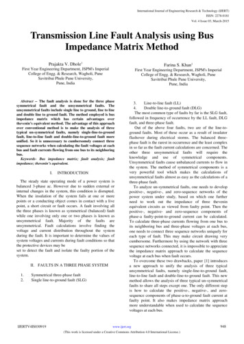
5Fast Bus Busbar SystemIndustrial Control Product Catalog 2021Section contentsFast Bus busbar adapter system60 mm systemPageSelection and ordering data5/25/35/35/10-5/15FBCB Fast Bus circuit breakersFBCB Fast Bus main and feedercircuit breakersFast Bus combination startersPage3RA2 Fast Bus combinations starters3RA6 Fast Bus compact startersSelection and ordering dataSelection and ordering data Fast Bus circuit breakers assemblies and kits Fast Bus adapter shoes for VL breakersPOWER DISTRIBUTIONSYSTEMSOverviewIntroductionTechnical DataDimension drawings5/95/115/65/65/65/65 Busbar holders Fast Bus adapter shoes Incoming supply terminals Copper busbar Busbar covers Other accessories5/75/8 See Section 4Smart Infrastructure, Industrial Control Catalog 20215/1
Fast BusFast Bus Busbar Adapter SystemOverviewBusbar adapter systemsPOWER DISTRIBUTIONSYSTEMS5Busbar adapter systemswith busbar centerline spacing of 60 mm60 mm busbar systemfor sharp-edged copper busbarsto DIN 46 433,width 20 mm to 30 mm,thickness 5 mm and 10 mm5/2PageBusbar holderEnd and intermediate holdersfor flat copper profiles5/6Fast Bus main circuit breakersfrom 15 to 500A5/6Fast Bus circuit breakersfrom 15 to 500A5/7Smart Infrastructure, Industrial Control Catalog 2021Page3RA2 Combination StartersIncoming supply terminalsseesection 45/6
Fast BusFast Bus Busbar Adapter SystemIntroductionGeneralFeaturesBenefitsThe Fast Bus Multi-Motor Control systemis a 3-phase insulated busbar systemand is ideal for space saving in paneldesigns. The system saves considerableline side wiring and space for multi-motorpanels. It is also ideal for panels whereseveral feeder breakers are used and willsave significant wiring space and wiringlabor. The system is also ideal for futureexpansion planning. when buildingcontrol panels. SIRIUS 3RV/3RT startercombinations and Siemens circuitbreakers are all adaptable to Fast Bus forconvenient mounting and faster replacement times. Simple economical installation Saves installation time Compact design Reduces space requirements Requires fewer mounting holes Minimizes layout time Domestic and International approvals Allows flexibility for domestic andexport business Touch safe Protection for maintenance personnel Modular design Improves equipment mounting density Provision for system expansion Reduces time and costs associatedwith system expansion Clip-on shoes provide mechanicaland electrical connections to panelmounted busbars Reduces mounting and wiring timeand provides trouble free connections Main and Feeder breakers mount tobusbars Allows for quick retrofitting of breakersFast Bus is ideal for industrial applications where system availability isimportant.How to Select Fast Bus1) Determine the required load.2) Select method to power Fastbus.5—Main lug up to 800A using a singleset of lugs or up to 1400A using adouble set of lugs.POWER DISTRIBUTIONSYSTEMS—Circuit breakers, 15A to 500AIf load exceeds 500A, the CB must beseparately panel mounted and fed toa main lug infeed module.3) Select 3RV MSP & 3RT contactorcomponents and appropriate adaptershoe or select preassembled 3RAstarters. See section 4.4) Select appropriate length busbar,busbar holders, insulation coversand any other required components.General Ratings of Fastbus SystemIECDomesticRated operating voltage690V600VRated insulation voltage, IEC VDEAC 1000VN/ATemperature stabilityUp to 105 degrees CN/ABusbar support and adapter shoe materialGlass-reinforced polyamideSameColorRAL 7035, light graySameAmpacityBusbar thickness and width362AFor technical informationon E and F frame circuitbreakers used as mainand feeder breakers, seesection 17Thermal busbar currents, E-Cu, bare, at 35 C ambient temperature inaccordance with DIN 43 67115 x 20 mm3/16” x 3/4”5 x 25 mm3/16” x 1”432A5 x 30 mm3/16” x 1 1/8”500ABusbardimensionsSystem10 x 20 mm3/8” x 3/4”564Ammmm20 x 525 x 530 x 560606027432737936243250043051359520 x 1030 x 10606042757356475667090010 x 25 mm3/8” x 1”660A10 x 30 mm3/8” x 1 1/8”756A720mm2---1400AThermal current at85 C65 CBusbar temperatureAA105 CASmart Infrastructure, Industrial Control Catalog 20215/3
Fast BusFast Bus Busbar Adapter SystemIntroductionFast Bus set-upThe Fast Bus system is designedto be easy to use and to saveset up time.POWER DISTRIBUTIONSYSTEMS58US Busbar holdersThe 8US busbar holders aredesigned to accommodateampacities up to 1400A. In somecases, the busbar holder willaccept busbars in either 5mm or10mm widths. Refer to page 5/6for selection details.High quality materialBusbar supports and fuse basesare manufactured from glassfiber reinforced, thermoplasticpolyester with thecolor RAL 7035, light gray. Thematerial ensures excellentmechanical, chemical and electrical properties. Furthermore,the material has an extremelylow flammability and meets therequirements of UL 94 V0.8WC Busbar andbusbar systemsThe most common size busbarfor applications in the US is the8WC5053 (20 mm x 5 mm), however there are other styles available depending on your application.Busbar systems with 60 mm busbar center-to-center clearancehave now become firmly established in the US market.The permissible busbar temperature is a decisive factor whendimensioning the busbars. Thebusbar temperature is dependent on the current, the currentdistribution, the busbar crosssection, the busbar surface, theposition of the busbar, the convection and the ambient temperature. The values stated in thetable on page 5/3 can only beconsidered as reference valuesbecause the conditions varywith each location. The valuesare based on constant currentover the whole busbar length.The trend toward busbarsproves most advantageouswhen the incoming supply iscentrally located and the load isdistributed symmetrically onboth sides.For the assemblies of a busbarsystem in the feeder circuit theUL directives specify components with large clearance in airand creepage distances (seethe table below). Components ofthe 8US1 busbar system whichmeet this requirement can befound in this chapter.Note:The design of an 8US1 busbarsystem for use in the feeder circuit always presumes the use ofthe UL base plate (8US19 222UA01) so that the clearance inair and creepage distancerequirements are met.Clearance in airCreepage distance25.4 mm (1 inch)50.8 mm (2 inch)Between live parts and grounded, 25.4 mm (1 inch)non-insulated metal parts25.4 mm (1 inch)Between live parts5/4Smart Infrastructure, Industrial Control Catalog 2021Feeder/branch circuitaccording to UL 508AThe feeder circuit is that part ofa circuit which comes in front ofthe last short circuit protectiondevice (SCPD). The branch circuit is that part of the circuitwhich follows after the last shortcircuit protection device. Whenthe 8US1 busbar system is usedin a switchgear which mustcomply with UL directives, it isimportant to establish whether itis to be used in the feeder circuitor the branch circuit. Components used in the feeder circuitrequire larger clearance in airand creepage distances than inthe branch circuit.Simple Fast Bus systemThe two illustrations above showthe very basic items neededwhen setting up a Fastbus system.8US1 Busbar holder (5/6)8US1 Ground busbar support(shown attached however can bemounted separately 5/6)Ground busbar available in5 x 20 mm to 10 x 30 mm8WC Busbar (8WC5053shown) FBB36 Busbar (5/6)Short-circuit strengthThe short-circuit strength of thebusbar system is dependent onthe spacing of the busbar holders and on the busbar crosssection.The short-circuit strength of thewhole system is dependent onthe short-circuit strength of thebusbar system and thecomponents that are mountedto the system.ApplicationsThe 8US Fast Bus distributionsystem is ideal for control panelbuilders with multiple motorapplications. These applications are most common in thematerial handling, automotive,food processing, pharmaceutical and paper processingindustries.
Fast BusFast Bus Busbar Adapter SystemIntroductionFast Bus combination starters and group installation assembliesRatings for Group Installations perNEC 430-53Standard Installation, NEC 430-52Group Installation, NEC 430-53Group Installation is an approach to building multiple motor control systems inaccordance with Section 430-53 of theNational Electrical Code. In Group installation, multiple motor starters can begrouped under one short circuit protectivedevice. The 3RV MSPs have been ULlisted for use in Group Installations bothwith and without 3RT contactors whenmounted on the Fast Bus system. A 3RTcontactor is added when remote operation of the motor is 163.5-12.53.5-2528-3236-4011-5028-100The selection of components forGroup Installation is a simple process of the following three steps:1. Selection of the Branch Circuit Protective Device, fuse or circuitbreaker.2. Selection of the 3RA Motor Starterbased on the motor Full Load Amps.Maximum rating of Group BranchCircuit Protective DeviceShort CircuitFuseCircuit BreakerThe main fuse shouldbe selected based onthe FUSE selectionprocedure listed below.The main CB should beselected based on theCIRCUIT BREAKERselection procedurelisted below.Circuit Breaker SelectionSelect a circuit breaker (CB) between:Minimum CB size (per NEC430-110):Sum of all motor FLC (per NEC table430-150) x115%.Maximum CB size (per NEC430-53c):250% x FLC of the largest motor FLC of all other motors.Current Ratings 1) 2)240V 480V 50kA12kA65kA65kA30kA—30kA———25kA30kAFuse SelectionCalculate the maximum fuse size perNEC430-53c.Max Fuse Size 175% x FLC of largest motor FLC of all other motors(FLC’s from NEC table 430-150).Short CircuitCurrent Ratings (Type E) 1 A—30kA——25kA30kA—Branch Circuit Protective Device for 480V-Ratings: The appropriate BCPD need to be determined in accordance with the National Electrical Code, Article 430-53 and theapplication. The following devices are permitted:Fuses: Classes RK1, RK5, J, G, T, CC or Circuit breakers: Listed Siemens type, with a marked short-circuit rating equal or larger than the available short-circuitcurrent rating. These devices were tested for group installation use at the above levels without any upstream branch circuit device.2) 3RA2 used as Manual Motor Controller; Branch Circuit Protective Device for 600V-Ratings: Max. Class J 50A3) Starter sizes S00,S0 and S3 require additional type E line side terminal adaptors on the MSP for type F applications. See section 1 accessories1)Smart Infrastructure, Industrial Control Catalog 20215/5POWER DISTRIBUTIONSYSTEMSFLAAmpRange5MSPType
Fast BusFast Bus Busbar Adapter System60 mm systemSelection and ordering dataBusbar holderInsulating Base PlateBusbar 3-phaseEnd coverBusbar holderInsulating Base PlateEnd coverBusbar 3-phaseBusbar Neuteral or PEGround busbar holderTerminals for RoundConductorsBusbar Neuteral or PETerminals for RoundConductorsPOWER S1948-2AA00Base plate3-pole system flatCopper Busbar with tin plating20 mm x 5 mm x 914 mm (36”)20 mm x 5 mm x 1524 mm (60”)20 mm x 5 mm x 2000 mm (78.74”)25 mm x 5 mm x 2000 mm (78.74”)30 mm x 5 mm x 2000 mm (78.74”)20 mm x 10 mm x 2000 mm (78.74")30 mm x 10 mm x 2000 mm (78.74")720 mm2 x 2400 mm (94.49”)UL Currentrating230 mm x 1100 mmfor 60 mm systemsfor 60 mm systemsfor 60 mm systemsfor 60 mm systems 4)for 60 mm systemsfor 60 mm systemsfor 60 mm systemsTwin T (TT) Busbar—362A362A362A432A500A564A756A1400ABusbar holder (end and intermediate)3-pole with inside mountingfor 20 mm and 30 mm x 5 mm or 10 mm —3-pole with inside mountingfor 25mm x 5mm or x 10mm—8US1923-3UA01 3-pole with inside mountingfor Twin T (TT) w/ end 08AOrder No.Compliance1)required8US19 22-2UA01FBB363 pcsFBB603 pcs8WC50538WC50548WC50558WC50638WC50658US19 48-2AA00yes—yes8US19 23-3UA018US19 23-3AA008US19 43-3AA01Busbar holder end cover3-pole end coverfits 8US19 23-3UA01 and 8US1923-3AA01requiredGround Busbar holder1-pole with inside mounting8US19 22-1AC00for 20 mm - 30 mm x 5 mm or 10 mm2)n/a8US19 23-1AA01Cover profiles for Busbarsfor 5 mm busbars up to 30 mm widefor 10 mm busbas up to 30 mmfor Twin T (TT) busbar1000 mm length1000 mm length1000 mm lengthrequiredrequiredrequired8US19 22-2AA008US19 22-2BA008US19 EA00 4 pcs8US1922-2EA01 8 800Ayes5SH35388US19 21-1BA008US19 21-1AA00FBT600F8US19 41-2AA038US19 41-2AA04—yes8US19 22-1GC00Reserve Space Cover (for covering round terminals placed on 3-phaseHolder for reserve space cover32mm heightHolder for reserve space cover107 mm lengthReserve space cover195mm height / 700mm lengthFeeder Lugs (mounts to all busbar sizes on this page)3-pole terminal plate with cover20 mm x 200 mm 16-4 AWG3-pole terminal plate with cover54 mm x 200 mm 10-2/0 AWG3-pole terminal plate with cover81 mm x 200 mm 2 AWG-250 MCM3-pole terminal plate with cover180 mm x 200 mm 250-600 MCM3-pole terminal plate154 mm x 184 mm 300-600 MCM5SH3538160 mm x 184 mm for flat bars up to8US1921-1BA00 3-pole terminal plate32 mm x 20 mmCover for 8US19 41-2AA03 and bar)8US1922-2EB00FBT600F w/coverGroundbusbarholder180 mm x 200 mm x 90 mm1) UL 508A labeled panels require the use of components that meet the creepage and air distances of 1” air clearance and 2” creepagedistance. N/A not applicable for given item.2) Current rating dependent on size of busbar used. Refer to busbar selection data.Smart Infrastructure, Industrial Control Catalog 2021Product Category IEC
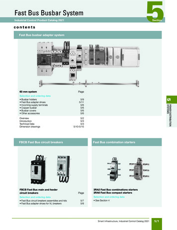
Fast BusFast Bus Busbar Adapter System60 mm system – Circuit breaker assemblies and kitsSelection and ordering dataDescriptionFBCB Fast Bus circuit breakersOffer a full range of feeder circuit breakers from 15A to 500A.All Sentron kits 125A and under are pre-assembled on 60 mmFast Bus adaptor shoes and ready to place on the busbar.All other circuit breaker kits are pre-packaged for fast userassembly and must be torqued down to the busbar prior toassembly. For VL breakers, adaptors are available for up to500A breakers (both main and feeder orientation).See page 5/8.3VA and GG Feeder Circuit BreakersBus bar system for 3VA circuit breakersare available from 15A up to 500A.For molded case circuit breakers / SCCR RatingTypePart NumberBusbar adapter system with60 mm busbar center-to-centerspacing, 3-pole8US1211-4SS003VA5 & GG 125A65KA @ 480VAC8US1213-4AP03—8US1213-4AH04—3VA5 250A100KA @ 480VAC3VA6 150A-250A150KA @ 480VAC——————3VA5 400A-500A100KA @ 480VAC3VA6 400A-500A150KA @ 480VAC————3VA and GG Main Circuit BreakersBusbar adapter system with 60 mmbusbar center-to-center spacing,top-fed, 15A to 500A 60A70A80A90A100A110A125AFBCB1003 pole/600V kitted components for customerassembly that require the adaptor to be torqueddown to the Busbars prior to assembly.150A175A200A225A250AHHED �Sentron Main Circuit BreakersFXD �FXD �FBCB150FBCB175FBCB200FBCB225FBCB250Breaker Frame (SCCR Rating)UL Current Rating3 pole/600V kitted components for customerassembly that require the adaptor to be torqueddown to the Busbars prior to assembly.FBCB250MED B110FBCB125POWER DISTRIBUTIONSYSTEMSSentron and GG Feeder Circuit Breakers3 pole/600V fully assembled breakers andadaptors that quickly snap onto the Busbar.DesignBreaker Frame (SCCR Rating 1))UL Current 225MFBCB250MHFXD �—1) UL Short Circuit Current ratings are based on 480V. Contact Siemens for 600 V ratings.2) FBCB100M -125M SCCR 25kA @ 480VFBCB150M -250M SCCR 65kA @ 480VProduct Category IECSmart Infrastructure, Industrial Control Catalog 20215/7
Fast BusFast Bus Busbar Adapter System60 mm system – Busbar adapters and device holdersSelection and ordering dataBusbardeviceadaptersAdapter Adapter Rated UL508A1)Number Rated Conof mount- current necting length widthvoltage complianceing railscablesUL(35 mm)AAWGmmmmVOrder No.PackunitsWeightper PUapprox.kgFor SIRIUSSize S00/S08US12 51-5DM07MSPs1251218245600yesContactors Overload relays1251218245600yes8US12 51-5DM070.1830.183Direct start loadfeeders1251218245600yes8US12 51-5DM070.183Busbar adapters1251218245600yes8US12 51-5DM070.183 Device holders1----18245600yes Connectingplates------------yes8US19 98-1AA001121418245600yes8US12 51-5CM470.1908US12 61-5FM080.263Reversing feeders8US21 51-5DM07Size S00/S0Cage ClampDirect start loadfeeders8US21 60-5AM00POWER DISTRIBUTIONSYSTEMS5Size S28US12 50-5AM000.158100 units0.100MSPs150818255600vyesContactors Overload relays150818255600yes8US12 61-5FM080.263Direct start loadfeeders150824555600yes8US12 61-5FP080.292Busbar adapters150824255600yes8US12 61-5FP080.292Busbar adapters1----24255600yes Device holders------24255600yes Connectingplates------------yes8US19 98-1AA0080421572600yes8US12 11-4TR00 0Reversing feedersSize S38US12 60-5AM000.2028US12 60-5AP000.243100 unitsFBS100723R0.1000.6590.5908US12 11-4TR00For VL UL circuit breakers 2)8US12 13-4AQ03VL150 UL,DG frame--150Tubular 190contacts105600yes8US12 13-4AQ031.020VL250 UL,FG frame--250Tubular 190contacts105600yes8US12 13-4AQ031.020VL400 UL,JG frame--400Tubular 296contacts140600yes8US12 13-4AH001.900--540 3)296140600yes8US12 13-4AH001.900VL400X UL,LG frameTubularcontacts8US12 13-4AH001)UL 508A labeled panels require the use of components that meet the creepage and air distances of 1” air clearance and 2” creepage distance. N/A not applicable for given item. 2)For use with 10mm x 30mm and twin T (TT) busbars only. Adaptors can be configured for main or feeder breakers applications.3)For use with maximum 500A circuit breaker. Circuit breakers greater than 500A must be panel mounted off the busbar system and fed to the busbars via an infeed module. See page 5/6.4)Rated 100A @ 480V. Rated 100A @ 600V with Class J Fuses.5/8Smart Infrastructure, Industrial Control Catalog 2021Category* You can order this quantity Productor a multiplethereof.IEC
Fast BusFast Bus Busbar Adapter System60 mm system – Terminals and accessoriesSelection and ordering dataDescriptionMaxAmpsWidthUL508AOrder No.Compliance1)ListPackPrice UnitsTerminals for round conductorsTerminals5 mm busbar thickness 3)12 mm x 5 mm15 mm x 5 mm20 mm x 5 mm25 mm x 5 mm30 mm x 5 mm20 mm x 5 mm, 25 mm x 5 mm30 mm x 5 mm10 mm bar thickness12 mm x 10 mm3)15 mm x 10 mm3), 20 mm x 10 mm25 mm x 10 mm, 30 mm x 10 mmTerminals20 mm x 10 mm, 25 mm x 10 mm30 mm x 10 mm16 - 6 AWG12 - 2 AWG6 - 2/0 AWG6 - 250 MCM16 - 6 AWG12 - 2 AWG6 - 2/0 AWG6 - 250 MCM3/0 - 350 MCM300 - 600 MCM8US19 21-2AA008US19 21-2AB008US19 21-2AD008US19 21-2AC008US19 21-2AA018US19 21-2AB018US19 21-2AD018US19 21-2AC018US19 41-2AA018US19 050060016 - 6 AWG12 - 2 AWG6 - 2/0 AWG6 - 250 MCM16 - 6 AWG12 - 2 AWG6 - 2/0 AWG6 - 250 MCM3/0 - 600 MCM300 - 600 MCM8US19 21-2BA008US19 21-2BB008US19 21-2BD008US19 21-2BC008US19 21-2BA018US19 21-2BB018US19 21-2BD018US19 21-2BC018US19 41-2AA018US19 41-2AA0210050505015151515638US19 22-1GA00108US19 22-1GA021Accessories for busbar adapters and device holdersMounting Rail8US1998-1BA00FBC20FBC135Mounting rail (35 mm) - plasticcomplete with mounting screws45 mm55 mm70 mm90 mm110 on holder(for vertical bubar assembly)fixes the MSP to the mounting rail 3) (for SIRIUS sizes S00/S0)-n/a8US1998-1DA0020Screw holderfor supplementary screw fixing of the feeder(for SIRIUS sizes S00/S0)-n/a8US1998-1CA0020Spacerfixes the busbar adapter to the device holder(for SIRIUS sizes tion wedgesfor mechanical linking of adapters and switching device holders(2 units required per combination)-n/aFBC202045 mm54 mmn/an/a8US1998-8AM078US1998-8AA10182 mm 10 mm200 mm 9 mmn/an/a8US1998-2BM008US1998-2BJ10Outgoing terminal rail for busbar adaptersLoad SideTerminalPlug-type terminal(complete with supporting element for attaching to busbar adapterand switching device holder. Spring loaded terminals.)3 x 14 AWG (400 V) and 4 x 16AWG (250 V)7 x 14 AWG (400 V)Accessories for busbar adapters and device holdersSide module for busbar adapter expansion For adapters w/182 mmSide module for busbar adapter expansion For adapters w/200 mm91 mm91 mm8US1998-2BM001)UL508A labeled panels require the use of components that meet the creepage and air distances of 1” air clearance and 2” creepage distance.N/A not applicable for given item.Terminals must be manually spaced on the busbar to comply with UL508A distances of 1” air clearance and 2” creepage distance.3) Cannot be used on Twin T (TT) profile up to 1400 A.2)Product Category IECSmart Infrastructure, Industrial Control Catalog 20215/9POWER DISTRIBUTIONSYSTEMSTerminal covers for circular conductors (mounts to busbars)For terminals up to 250 MCM200 mm long, 84 mm wideFor terminals up to 600 MCM200 mm long, 270 mm wide8US19 22-1GA00For terminals up to 600 MCM200 mm long, 135 mm wide5180270400440180270400440500600
Fast BusFast Bus Busbar Adapter System60 mm systemDimension drawings8US19 23-3UA013150.187(5)36 (914)FBB6060 (1524)NSE0 02058AFBB361124001573402091207550L312351Support for blanking covers,8US1922-2EA008US19 22-1AC00 with 8US19 23-3UA018US19 22-1AC00 with 8US19 23-3AA01326040104030200610NSE0 02073NSE0 02070930,5NSE0 00720Length 1000 mmBlanking cover, 8US1922-2EB00NSE0 0072110,25,28US19 23-1AA0149,462,58US19 22-2BA008US19 22-2AA0030,5Length 1000 mm603431405/10Smart Infrastructure, Industrial Control Catalog 2021NSE0 0207271781,562,52008US19 22-2DA00NSE0 016075POWER DISTRIBUTIONSYSTEMSL2L325Copper Busbar/TT profile, 8US19 48-2AA006L1NSE0 020712L1660.75(20)Dimension25L1185A8US19 43-3AA0031FBB36/FBB60 Copper Busbar
Fast BusFast Bus Busbar Adapter System60 mm systemDimension drawingsInfeed, 8US19 21-1BA00Infeed, 8US19 41-2AA03282329636NSE0 02074NSE0 0206054156184602001946094502115488Infeed, 8US19 21-1AA0072100Infeed, 8US19 41-2AA0450528,71481841948828NSE0 0205360NSE0 020593272100,2FBT600F CoverFBT600F (supplied with cover)Infeed 5SH35388,81608834166I2 13999a6019420060146202832180Smart Infrastructure, Industrial Control Catalog 20215/11POWER DISTRIBUTIONSYSTEMS2006094581
Fast BusFast Bus Busbar Adapter System60 mm systemDimension drawingsBusbar device adapter, 8US12 50-5AM00Busbar device adapter, 8US12 60-5AP006065205NSE0 0205160102421823,4Busbar device adapter, 8US12 61-5FM0851,7Busbar device adapter, 8US12 11-4TR00560Ø2,23,760,226,554,54160728,5Busbar device adapter, 8US12 61-5FP08606201485324218260182555NSE0 020632056481701210Busbar device adapter, 8US12 3,760,28,5Smart Infrastructure, Industrial Control Catalog 2021NSE0 02061,5Ø347,45423,760,28,5NSE0 020686018252142001646060NSE0 0206240562012681485POWER DISTRIBUTIONSYSTEMS23,747,453,8
Fast BusFast Bus Busbar Adapter System60 mm systemDimension drawingsBusbar device adapter, 8US12 51-5CM47114,5114,5190602331,538,8Busbar device adapter, 8US12 13-4AQ0135105NSE0 02066POWER DISTRIBUTIONSYSTEMS182643NSE0 02069131,5131,51906035,526,8523Busbar device adapter, 8US12 13-4AQ038US19 98-2BM001435105NSE0 02065Busbar device adapter, 8US12 13-4AH006056242702963242247,51445140NSE0 0206755Smart Infrastructure, Industrial Control Catalog 20215/13
Fast BusFast Bus Busbar Adapter System60 mm systemDimension 23.520.522.5293632253555425555101012124 Nm6 Nm15 Nm10 Nm10mm 0101010101012124 Nm6 Nm15 Nm10 Nm85,5Max tighening torquemax. 98Type5mm5143408US1941-2AA028US1921-2A / -2Bmax. 8442max. 865143POWER DISTRIBUTIONSYSTEMS531388US1922-1GA0060848US19 22-1GA025/14Smart Infrastructure, Industrial Control Catalog 202110 32355519420018960FBC135
Fast BusFast Bus Busbar Adapter System60 mm systemDimension drawings8US19 98-1DA008US19 98-4AA008US19 98-7CA08298US19 98-7CA108US19 98-7CA15297490359148US19 98-1BA008US19 98-8AA1058US19 98-8AM078US19 98-7CA167NSE0 01599278US19 98-1CA00POWER DISTRIBUTIONSYSTEMS8US19 98-1CA008US19 98-1DA00Smart Infrastructure, Industrial Control Catalog 20215/15
Fast BusCombination Starters & Starters for Group InstallationSIRIUSBusCombination Starters and Group Installation AssembliesSIRIUS3RA3RA2FastMotorStartersGeneral dataGeneral dataOrder No. schemeDigit of the Order No.SIRIUS starters1st 3rd4th 5th 6th 7th@@@@3RASIRIUS 2nd generationType of starter (direct-on-line starter 1,reversing starter 2)2@0@8th 9th 10th 11th 12th–@@@@@@@@@13th 14th 15th 16th–@@@@@@K6@Size (S00 1, S0 2)@Setting range for overload releaseDesign type and connection method@Rated power at 460 V ACIntegrated auxiliary switches of the contactor@Operating range / solenoid coil circuit (contactor)Rated control supply voltage (contactor)Example@3RA2110–0BA15–1ANote:The Order No. scheme is presented here merely for information purposes and for better understanding of the logic behind the ordernumbers. For your orders, please use the order numbers quote in the catalog in the Selection and ordering data.Technical specificationsSizeConnection methods MountingControl voltageWidth WHeight HDepth DmmmmmmMounting dimensionsS003RA21 1.Screw terminalsStandard mounting railsAC/DC4516797Busbar adaptersAC/DC45200155AC/DC4519897Busbar adaptersAC/DC45260155Standard mounting 5243107Busbar adaptersAC/DC45260165Standard mounting railsAC/DC9017097Busbar adaptersAC/DC90200155AC/DC9020497Busbar adaptersAC/DC90260155Standard mounting railadaptersAC90265120.3DC90265130Busbar 0165Spring-type terminals Standard mounting railsS03RA21 2.Busbar adaptersDWScrew terminalsSpring-type terminals Standard mounting railsReversing starters3RA22.S003RA22 1.Screw terminalsSpring-type terminals Standard mounting railsS03RA22 2.Screw terminalsSpring-type terminals Standard mounting railadaptersBusbar adaptersTypeSizeNumber of poles3RA2. 1S003Mechanics and environmentPermissible ambient temperature During operation Storage and transport C C-20 . 60-55 . 80Weightkg0.6 . 1.5Permissible mountingpositions0.8 . 2.3229Shock resistance(sine-wave pulse)Acc. to IEC 60086 Part 2-27Degree of protectionAcc. to IEC 60947-15/166/103RA2. 2S03gSmart Infrastructure, Industrial Control Catalog 2021SIRIUS Innovations Supplement 20129223 9Direct-on-line starters3RA21.H6POWER DISTRIBUTIONSYSTEMS 5Direct-on-line starters/reversing startersImportant: Acc. to DIN 43602 start command "I" at the right or topUp to 6Up to 6IP20
Combination Starters & Starters for Group InstallationSIRIUS 3RA Motor StartersGeneral dataDirect-on-line starting For 60 mm busbar systems Sizes S00 and S060 mm busbar adapterfor screw terminals8US12 51-5DS10 for S008US12 51-5NT10 for S0Motor starter protectorSize S00/S0Screw terminalsLink module3RA19 21-1DA00 for S003RA29 21-1AA00 for S0, AC contactor3RA29 21-1BA00 for S0, DC contactorLink module3RA29 11-2AA00 for S003RA29 21-2AA00 for S0 1)ContactorSize S00/S0Spring-type terminals1) Additional3RA29 11-1CA00spacer for height compensationon AC contactors size S0 withspring-type terminals.Right: 3RA21 motor starter for direct-on-line starting with busbaradapters with spring-type connection3RV204 with 3RT2043RV203 with 3RT203Adapter Shoe8US1261-5FP08MSP3RV203Link Module3RA2931-1A AC/DCContactor3RT203NSB0 02091aAdapter Shoe8US1211-4TR00MSP3RV204Link Module3RA1941-1A AC/DCContactor3RT204BracketFBS0 070BSmart Infrastructure, Industrial Control Catalog 20215/17POWER DISTRIBUTIONSYSTEMSLeft: 3RA21 motor starter for direct-on-line starting with busbaradapters with screw connectionMotor starter protectorSize S00/S0Spring-type terminals5ContactorSize S00/S0Screw terminals60 mm busbar adapterfor spring-type terminals8US12 51-5DT11 for S008US12 51-5NT11 for S0
Fast BusSIRIUS 3RA Fast Bus Combination Starters and Group Installation AssembliesSelectionReversing duty For 60 mm busbar systems Sizes S00 and S0RS assembly kit for reversing duty andbusbar mountingScrew connection:3RA29 13-1DB1 for S003RA29 23-1DB1 for S0For spring-type connection:3RA29 13-1DB2 for S003RA29 23-1DB2 for S0 1)Comprising:1 wiring kit1 busbar adapter1 device holder2 connecting wedges1)60 mm busbar adapterFor screw terminals:8US12 51-5DS10 for S008US12 51-5NT10 for S0For spring-type terminals:8US12 51-5DT11 for S008US12 51-5NT11 for S0Also includes 3RA29 11-1CA00 spacerfor height compensation on AC contactorssize S0 with spring-type terminals.Motor starter protectorSize S00/S0Screw terminals/spring-type terminals2 connecting wedges8US19 98-1AA00POWER DISTRIBUTIONSYSTEMS5Link moduleFor screw terminals:3RA19 21-1DA00 for S003RA29 21-1AA00 for S0, AC contactor3RA29 21-1BA00 for S0, DC contactorFor spring-type terminals:3RA29 11-2AA00 for S002)3RA29 21-2AA00 for S060 mm device holder8US12 51-5AS101NSB0 02094b32 contactorsSize S00/S0Screw terminals/spring-type terminals422)Additional 3RA29 11-1CA00 spacerfor height compensation on AC contactorssize S0 with spring-type terminals.3RA22 motor starter for reversing duty and 60 mm standard
5/4 Smart Infrastructure, Industrial Control Catalog 2021 Clearance in air Creepage distance Between live parts 25.4 mm (1 inch) 50.8 mm (2 inch) Between live parts and grounded, non-insulated metal parts 25.4 mm (1 inch) 25.4 mm (1 inch) The short-circuit strength of the busbar system is dependent on the spacing of the busbar hold-