Transcription
v.: 2.0.6 2018-08-14 / FW1.72CS141 User Manual EnglishUPS WEB/SNMP MANAGER1
v.: 2.0.6 2018-08-14 / FW1.72Copyright Statement for Intellectual Property and Confidential InformationThe information contained in this manual is non-conditional and may be changed without due notice. Although Generex hasattempted to provide accurate information within this document, Generex assumes no responsibility for the accuracy of thisinformation.Generex shall not be liable for any indirect, special, consequential, or accidental damage including, without limitations, lostprofits or revenues, costs of replacement goods, loss or damage to data arising out of the use of this document.Generex the manufacturer of the BACS products undertakes no obligations with this information. The products that aredescribed in this brochure are given on the sole basis of information to its channel partners for them to have a betterunderstanding of the Generex products.Generex allows its channel partners to transfer information contained in this document to third persons, either staff within theirown Company or their own customers, either electronically or mechanically, or by photocopies or similar means. Generex statesthat the content must not be altered or adapted in any way without written permission from Generex.It is agreed that all rights, title and interest in the Generex’s trademarks or trade names (whether or not registered) or goodwillfrom time to time of Generex or in any intellectual property right including without limitation any copyright, patents relating to theProducts, shall remain the exclusive property of Generex.Generex will undertake to deal promptly with any complaints about the content of this document. Comments or complaints aboutthe document should be addressed to Generex Systems GmbH.Copyright of the European Union is effective (Copyright EU).Copyright (c) 1995-2017 GENEREX GmbH, Hamburg, Germany. All rights reserved.2
v.: 2.0.6 2018-08-14 / FW1.72Table of ContentsIntroductionDifferences to the CS121Model OverviewDelivery notesFunction overview CS141Hardware LayoutInterface AssignmentExternal D-SUB 9-pin maleNetwork integration of the CS14156789111213Initial ConfigurationPreparation at the CS41Preparing the WorkstationDHCPFinding CS141 in networksNetfinderDifferences in operation modes141415161617Before you startInstallation examplesRequired Ports1820CS141 Basic settingsUser ManagementSetup WizardIP-address settings and hostnameLocation and contzact settingsProvided servicesDate and timeUser managementSystem overviewSwitching to operational mode212223242527282931System notificationEmail settingsAdvanced Mail OptionsTesting Mail SettingsThe most common error messageModbusEmail trapsSNMP Agent32333334343435UPS ConfigurationGeneral COM Port SettingsThe pipe through functionAutomatic UPS search featureConfiguration of a UPSUPS monitoring screenUPS functionsUPS event handlingBattery Health Level (%) featureRFC 1628 UPS InterfaceDifference between APC Smart Network and RFC 1628Managing jobsAvailable jobsUPS Shutdown definitionHow to configure a jobTime management of jobsAdding several jobsDeleting jobsCounter Events373839394142444545454646464849495050Custom ThresholdsWhat are Custom ThresholdsDifference Warning/Alarm LevelsExample scenario: Custom ThresholdsExemplary excerpt: Custom ThresholdsTutorial: Custom thresholds51515153543
v.: 2.0.6 2018-08-14 / FW1.72RCCMDWhat is RCCMDAvailable RCCMD CommandsConfiguration of RCCMDSetting an RCCMD JobSetting the IP address for RCCMDTiming for RCCMD jobsvariables for RCCMD traps55555556565758Sensors and devicesGeneral COM Port SettingsSM T H COM Standalone SensorSetting up a sensorSensor monitoring screenEvent handling for sensorsSensor related system eventsSetting up a jobSensor ManagerAlarm device / buzzerGSM modemCON AUX4 and CON R AUX46060616262626363656871SchedulerHow the scheduler worksSetting up scheduled Jobs7474Web Serversafety instructionsHTTP settingsPORT settingsForce HTTPsHTTP refresh timeSimple monitor757575767676DiagnosticsStatus bar and LED'sExample for error diagnostic7778LogfilesEvent LogData logData log Diagram798081ReboottracerNetwork ScanPrivacy Notice: Network ScansEvaluation of dataDeleting dataChanging Logo82828383838484ToolsData backup and updatesCreating backupsRestore BackupsPerforming a firmware updateChanging the OEM firmware85858686If nothing works .Rebooting without loginPerforming a firmware update directlyThe rescue mode on the CS141Rescue mode on the CS141 Mini88888890Appendix:Frequently asked questionsCopyright and Licenses91924
v.: 2.0.6 2018-08-14 / FW1.725
v.: 2.0.6 2018-08-14 / FW1.72IntroductionThank you for trusting the CS141 Webmanager – the most powerfull solution for critical resource management.Since the CS141 was designed to be a full-fledged, standalone manager, its task is not limited to gathering and sharinginformation. It also accomplishes numerous tasks in measurement controlling devices dealing directly with critical resourcemanagement. Furthermore, the CS141 comes with a full-featured message management system. The CS141 cannot onlyanswer requests coming from higher-level systems - it can also independently inform responsible employees in case of anemergency incident as well as initiating emergency measures based predetermined parameters:The CS141 can automatically activate basic or advanced emergency systems, shut down servers and workstations. Evenautomatic restart at predetermined conditions is configurable. In addition to standard technologies such as SNMP and Modbus,the CS141 relies on using the powerful RCCMD software solution. By doing so, even the emergency behavior of complex, fullyvirtualized server landscapes are realizable.Thanks to RFC1628 the CS141 provides more flexibility than everThis feature provides new possibilities to integrate third-party UPS systems. Thanks to the new RFC1628 compliant UPSinterface, administrators can use the CS141 to poll any SNMP card that supports these standards. Simply use the snmp-cardinstalled inside your UPS and display the current status natively inside CS141.This will allow administrators to use the powerfull products made by GENEREX in combination of UPS-Systems that arenormally not compatible.NoteDue to the fact the CS141 Web Manager can act as a stand-alone system for managing, it can be used flexibly in many areas,even outside the functionality described in this guide. This manual therefore describes the fundamentally implementedfunctionality according to UPS systems. However, the enormous flexibility and the possibility of communicating with higher andlower-level systems using standardized interfaces allows the adaption to very different possibilities to use.6
v.: 2.0.6 2018-08-14 / FW1.72Differences to the CS121Complete rework of the menu structure: The simplified interface combines a powerful hardware to provide asignificant performance boost:The powerful successor of the CS121 allows configuration in real-time - necessary system services will be started orstopped as needed. Therefore, a restart is only necessary in exceptional situations.Additional hardcoded user accounts according to specialized tasks:Engineer and Guest accounts are provided according to their tasks with limited system rights. On request the newguest account can be set up to allow external technicians a quick information overview without the need of passwordentry.The DIP switches known from the CS121 are no longer required and changed by a comfortable slide switch in thefront of the device:the easy-to-use slide switch will change the hardware configuration. Once the configuration state is chosen, a rebootcan be done by the removing power connection or software triggered.The firmware update can now be carried out inside a common browser via drag & drop. The need for external toolsand FTP access is no longer necessary.In case of problems with the firmware, updates or reboots can also be carried out without a complete login. To do this,use a commen webbrowser and enter the IP of the device followed by /update. After a successful adminauthentication, the firmware can now be updated and optionally resetted to factory settings.By default, auto logout is now enabled. On inactivity, the user is logged out of the system after 15 minutes.The power consumption of the CS141 has been reduced by a factor of 10 with a power increase and is well below thepredecessor model.Note:The CS121 has been discontinued in 2015 and replaced by the powerful successor CS141. The Software development wasofficially discontinued in 2018 - the current firmware state is frozen. Newer UPS systems and models are not available. If youuse a CS121 with a specific UPS manufacturer for many years, it may happen that your new UPS model is not nativley availableeven of you use the latest firmware version.In this case, it is advisable to move to the successor CS14.Model S141BSCCS141R 2CS141MINIFunctionSNMP adapterSNMP adapterSNMP adapterSNMP adapterSNMP adapterSNMP adapterSNMP adapterSNMP adapterRemarksexternal adapterSlot Adapter for UPS with slotExternal adapter with MODBUS output (RS485)Slot adapter with MODBUS output (RS485)External adapter BUDGET-Modell (No COM2- and AUX-port)Slot adapter BUDGET-Modell (No COM2- und AUX-port)Slot adapter for PILLER/CTA/RIELLO/AROS UPS ItalySlot adapter for UPS models with MINI SlotAdditional devices based on CS141:DeviceBACSKIT B4FunctionBattery managementRemarksExternal adapter7
v.: 2.0.6 2018-08-14 / FW1.72BACSKIT BSCCS141R 2CS141MINIBattery managementSlot adapterFeaturesAdditional Mini DIN 8 COM Port for RS232. AUXPort for Digital Input/Output. Remote RASManagement optional.Additional Mini DIN 8 COM Port for RS232. AUXPort for Digital Inpuit/ Output. Remote RASManagement optional.Additional Mini device. AUX Port for Digital Input/Output. Remote RAS Management optional.Supported UPS devicesOver 1400 UPS modells from over 80 different manufacturers aresupportedAdditional RS485. AUX Port for Digital Input/Output. Remote RAS Management optional.Slot Budget variant of the CS141. UPS Management via LAN. No AUX Port for floating contacts.No COM2 Port for Pipe-through, sensors, etc.Slot Budget variant of the CS141. UPS Management via LAN. No AUX Port for floating contacts.No COM2 Port for Pipe-through, sensors, etc.Additional Mini DIN 8 COM Port for RS232.Additional Mini DIN 8 COM Port for RS232.All devices with basic Slot SCAll devices with basic slot SCOver 1400 UPS modells from over 80 different manufacturers aresupportedOver 1400 UPS modells from over 80 different manufacturers aresupportedAll devices with basic Slot SCRiello and Aros UPS with Netman SlotUPS devices with MINI Slot (Soltec, Voltronic, etc)All CS141s can manage UPS systems providing a native serial protocol. Furthermore, the CS141 can be easily integrated intoexisting SNMP systems. All models of the CS141 family provide an own unique web server with configurable eventmanagement for automating job executions based on the status of the UPS. All CS141s can manage UPS systems providing anative serial protocol. Furthermore, the CS141 can be easily integrated into existing SNMP systems.All models of the CS141 family provide an own unique web server with configurable event management for automating jobexecutions based on the status of the UPS, including:- email notification- Full RCCMD funcinality- shutdown commands,- logfile entries, shutdown of the UPS, - graphical log files,- shutdown and wake-up -commands (WOL)In addition, the CS141 can also be individually configured using a scheduler to trigger job executions for many events, eg:- battery testing- calibration- UPS or system shutdown / restore.The CS141 provides a wide range of network management features to inform and alert required persons before a criticalincident occurs. The CS141 can even monitor other SNMP devices and thanks to its built in RCCMD solution, combine them toan intelligent power resource management.Each adapter has 2 years warranty as well as free updates for 3 years.All devices are manufactured in Germany8
v.: 2.0.6 2018-08-14 / FW1.72Content on deliveryThe scope of delivery of a CS141 includes a supplementary Software Compact Disk and additional hardware.Note:The budget edition does not support all features described in this manual.ProductIncluded on deliveryExternalpower �sMini-DIN-8manual on ConnectorCD(MODBUS)XXXXRS-485Via COM2RescueJumperXXXXXXXXXXCS141BSCXCS141R 2XXXCS141MINIXXFunction overview CS141In SNMP mode, the CS141 adapter works with a preinstalled Simple Network Management Protocol (SNMP) software agent.This agent exchanges status data with the UPS via so-called "get / set" commands and forwards them in the form of "trapmessages" to predetermined recipients. These "trap messages" allow to alert necessary persons during or before criticalsituations happen within the UPS. Typical information can be switching to battery power or the end of a power failure.In addition, the SNMP adapter can send RCCMD signals (Remote Control Commands):On clients with the RCCMD software installed, freely configurable functions can be triggered – the functionality range allownearly everything.Administrators can run a simple system shutdown as well as a highly complex shutdown and restart routine.In addition, the web interface is also a control of the UPS possible.9
v.: 2.0.6 2018-08-14 / FW1.72In SNMP mode, the CS141 adapter works with a preinstalled Simple Network Management Protocol (SNMP) software agent.This agent exchanges status data with the UPS via so-called "get / set" commands and forwards them in the form of "trapmessages" to predetermined recipients.These "trap messages" allow to alert neccessary persons during or before criticalsituations happen within the UPS. Typical information can be switching to battery power or the end of a power failure.In addition, the SNMP adapter can send RCCMD signals (Remote Control Commands): On clients with the RCCMD softwareinstalled, freely configurable functions can be triggered up to complex shutdown and start routinesIn addition, administrators can monitor and control their UPS possible by using the build in web interface to ensure a all-in-onesolution for nearly the entire UPS system:SNMP Trap functionalityThe basic task of the adapter is to communicate alarm states of the UPS to an according monitoring station (traps) or to provideUPS data if monitoring stations poll. With this function, e.g. the power supply and battery status of a UPS are monitored by anSNMP management station.Additionally, the CS141 provides functions for simulating and testing trap messages during configuration procedure.Remote Control:Due to the fact the CS141 is capable to configure it is possible to trigger different remote-controlled actions. Administrators canperform battery tests, bypass the UPS batteries or configure UPS behaviorNote:Depending on the UPS you are using, provided functions may differ.Compatibility according to third party network management systemsThe SNMP adapter is compatible with all common network management systems. All SNMP systems providing the compilationof a MIB - or already contain the Management Information Base (MIB) / Request for Comment 1628 (RFC) for UPS systems can be operated with CS141.Full RCCMD support:Due to the fact the CS141 is a full manager and not just an SNMP-Card to collect and provide data, the entire network shutdownroutine can be configured to react as fast as possible:Thanks to integrated RCCMD support, the CS141 offers a flexible and fast way to operate even the most complex shutdownsolutions. By the usage of standardized network technologies and protocols, the patented RCCMD server transfers controlcommands that are executed by the clients in real time.RS-232 / pipe-through:In some cases, different networks without any connections have to be configured to use the same UPS.With the new pipe-through capability administrators can connect two CS141 and let the communication of the UPS work withboth devices:By doing so, two different CS141 can communicate to according networks without additional hardware.RS232 UPS interface:The CS141 provides a standard RS232 interface to allow establishing a serial connection to any UPS providing this standard.Note:Please use only the original UPS communication cable supplied with the UPS. In case of using a contact UPS, choose thespecial designed cable of the manufacture. If you have any questions regarding special connection cables, refer your UPSdealer.Provided real-time logfiles:The CS141 provides a proven compilation of logfiles to reconstruct a complete timeline in case of critical incidents.This logfile is accessible via UNMS, UPSMAN, WebGUI and FTP or can be send via mail to configured mail-accounts.Advanced mailing capabilitiesEach model of the CS141 family provides the capability to connect to any mail server using standardized encryptiontechnologies.10
v.: 2.0.6 2018-08-14 / FW1.72Unique web server included:The unique build-in Web server of the CS141 displays all information about the device itself, connected sensor and externalhardware. The software module UPSView inside the CS141 can also be used to display a graphical representation of thesedata.To Access the web interface administrators and technicians may just use common browsers (Edge, Firefox, Chrome, Safarietc.).NetworkingModern UPS solutions are much more than just batteries. The Cs141 takes an eye on this fact and co-operates with the UPS:The UPS ensure power to all clients and the CS141 manages the solution to inform and finally to shut down all clients beforebatteries are depleted.MODBUS:Modbus is the standard protocol used in industrial applications for monitoring and building management.All devices of the CS141 family therefore provide as standard a MODBUS over IP interface. In addition, CS141 with COM2connector provide MODBUS over RS232 (CS141L & SC) and Modbus over RS485 (CS141L, SCM).SNMP:All models of the CS141 family communicate using SNMP via the UPS standard MIB RFC 1628.If a system does not include this standardized MIB, administrators can download the RFC1628 data file from www.generex.de tocompile the MIB at a later time.Once you have compiled the MIB file into the appropriate MIB directories of your SNMP station, the CS141 can be used.UPSTCP:CS141 provides with UPSTCP a complete API interface to ensure optimal integration into existing networks.Upon request, this interface specification can be supplied to manufacturers of software in order to enable their own integration.11
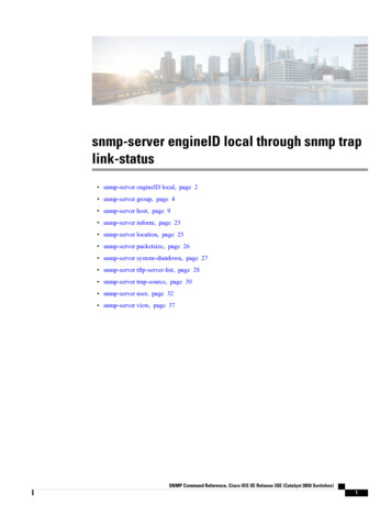
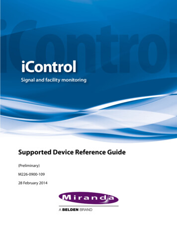
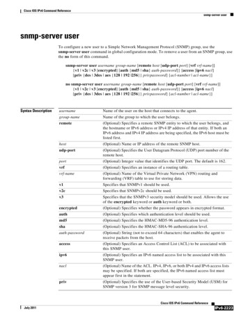
v.: 2.0.6 2018-08-14 / FW1.72Hardware .Slide-Switch for network configurationNetwork InterfaceCOM2 MINIDIN Connector for RS232COM2 Phoenix Connector for RS485Green and Red Status LEDAUX InterfacePoE HeaderDebug AdapterRescue Jumper: Open Normal Boot, Close Rescue BootNAND FlashCPURAMUSB InterfaceCOM1Slot InterfacePower SupplyDIP SwitchFuse12
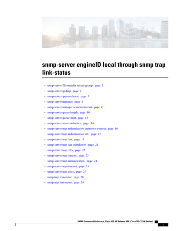
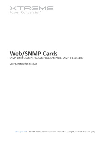
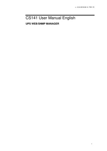
v.: 2.0.6 2018-08-14 / FW1.72Interface DescriptionExternal D-SUB 9-polig SPin4DTRPin9:RIPin5GNDSlot version: Circuit board connectionPinSignal name1GND28 – 34V DCLevelFunctionPower GroundPower Input3COM1 TXDV244COM1 RXDV24COM1 Receive DataSW GPIO 1 1) 2)3,3V TTLCS141DMINI: Functionality of DIP-Switch 16SW GPIO 2 1) 2)3,3V TTLCS141DMINI: Functionality of DIP-Switch 27POW# Input 1)3,3V TTLEnable power supply (active low)8Bridged with Pin 109GND10Bridged with Pin 811COM1 DTR 1)V24COM1 Data Transmit Ready12COM1 RI 1)V24COM1 Ring Indicator13COM3 RXD 1) 2)5V TTLCOM3 Receive DataCOM3 TXD 1) 2)5V TTLCOM3 Transmit Data15COM2 TXD 1) 2)3,3V TTLCOM2 Transmit Data16COM2 RXD 1) 2)3,3V TTLCOM2 Receive Data51417-261)2)-COM1 Transmit DataSignal Groundn.c.Connectable with solder bridge (MINI: resistor bridge)Input with Pull-Up13
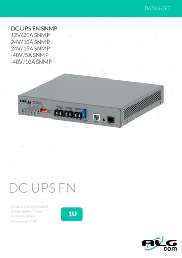
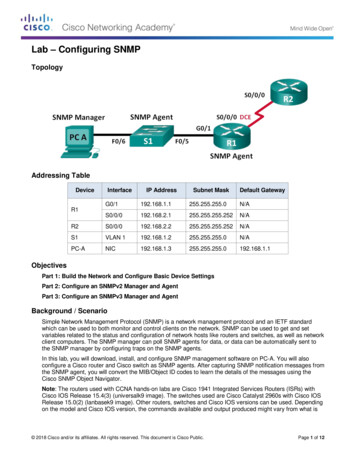
v.: 2.0.6 2018-08-14 / FW1.72Pin COM2 Mini-DIN 8 polMini DIN 8 socket eld- - - - - - - - - DCDRxDTxDDTRDSRRTSCTSRIGNDRS-485 (optional):Pin1 GNDPin2: - RS485/APin3: - RS485/B(-)AUX-Port (Hardware Revision 1.1 from Serial numbers 0121-1203, 0122-00198, 0123-00564 onwards) RJ11 6-polPin1:Pin2:Pin3:Pin4:Pin5:Pin6:- 3,3V- - - RxD (COM3 Input)- TxD (COM3 Output)- GND14
v.: 2.0.6 2018-08-14 / FW1.72Network integration of the CS141All models of the CS141 family are configured exclusively through the specially designed web interface.In order to facilitate the initial configuration or a quick on-site intervention, the CS141 family Web Manager is preset to the hardcoded IP address 10.10.10.10::You will recognize this presetting that the slide switch is in the middle position on the front side. Due to its more compact design,the CS141 MINI brakes the standard and uses on-board dip switches instead of a sliding switch.You will recognize this presetting that the slide switch is in the middle position on the front side. Due to its more compact design,the CS141 MINI brakes the standard and uses on-board dip switches instead of a sliding switch.The center position or alternatively both dip-switches set to off position activates the configuration mode:In this mode, some functions such as IP address data are configurable, but available only as soon as CS141 is switched toregular operating mode.The following table lists regular operating modes:Sliding switch center position / DIP 1 2 OFF:Enables configuration mode. After reboot the hard-coded IP address 10.10.10.10is active.Sliding switch to the right / Dip 1 OFF 2 DIP 2 ON:Automatic IP addressing: DHCP is activated and an IP address is setautomatically. Check the MAC address of your CS141 to identify the IP address inthe DHCP server table.Sliding switch to he left / DIP 1 ON DIP 2 OFF:Use of the IP address values manually configured. If DHCP is used, the IPaddress needs to be blocked for single usage.CS141 Mini special feature:Both Dip-Switches ON:Enables the rescue-mode for advanced system maintenance operation.15
v.: 2.0.6 2018-08-14 / FW1.72Initial configuration 10.10.10.10Preparation at the CS41Prior to commissioning, ensure the slide switch on the front is set to center position. In case of CS141Mini, both Dip switches ofthe CS141 MINI has to be set in OFF position. After start up, the CS141 can be runs in configuration mode, available at IPaddress 10.10.10.10.Note:Changing the mode via the hardware switches requires a reboot of the CS141. You can perform the restart in two ways:By removing the power supply (hardware reset)Using the Restart feature to be found inside the Tools menu (Software Reset)This operation does not apply the UPS the CS141 is connected to - the functionality will be kept up independently to the CS141.Preparing the WorkstationAfter starting, the CS141 Web Manager can be found using the following network address:IP address 10.10.10.10Subnet Mask: 255.255.255.0Depending on the type of connection you choose, the service computer can be connected directly to a crossover cable or viathe local network segment.This is recommended network settings for the client PC:IP address 10.10.10.11subnet mask of 255.255.255.0Gateway 10.10.10.11DNS: none16
v.: 2.0.6 2018-08-14 / FW1.72Obey whether the settings of your service computer work by opening a console in order to enter the commandPING 10.10.10.10.If the settings are correct, the CS141 will respond accordingly. As soon as the CS141 answers correctly, open a web browser.The CS141 web interface will be accessible by tipping http://10.10.10.10Adding a routeWithin larger installations with well-defined domain services, it may be helpful temporarily editing the routing table.In case of using a route, ensure the CS141 is located within the same network segment and is therefore directly accessibleExample: Adding a route into a Windows-driven Computer:1.Run the command console cmd as administratorThis is important due to the fact, Windows requires a user with local administration rights to add a route.2.Enter the following command: route add 10.10.10.10 IP address of your system Windows will accept the command and return OKIn order to check the new rout, enter the command route printUnder active routes, 10.10.10.10 should be seen. As an additional test, use the command ping 10.10.10.10 to verify the CS141web manager is responding as expected.17
v.: 2.0.6 2018-08-14 / FW1.72Note:In configuration mode, only one CS141 with the default IP address of 10.10.10.10 can be operated.If you connect several devices at the same time this way, a network conflict is unavoidable.Using the DHCP OptionThe DHCP modeSince the models of the CS141 family can fulfill many functions due to their flexibility, it is a very realistic scenario that you needto commission several devices at the same time within an installation procedure - Unfortunately there is no fixed IP address thatcan be assigned for the moment.To avoid a network conflict, activate the DHCP mode for automatic IP address assigning:Slide the slide switch to the right, i.e. to the outer edge of the CS141. For the CS141 Mini, set dip switch 1 to OFF and move dipswitch 2 to ON. Next reboot, the web manager will boot in DHCP mode according to the hardware configuration and obtain anIP address from your network.18
v.: 2.0.6 2018-08-14 / FW1.72Required information for finding CS141 in DHCP-ModeTo identify the devices, please note the MAC address including location data before proceeding hardware installation.The MAC address can be found on any CS141 web manager as a unique sticker:Ensure a suitable DHCP server is available for this operating mode, otherwise the will not be able to get valid IP address dataautomatically.Netfinder: Search for IP-addresses used with CS141 devicesThe Netfinder is a software tool that can display all CS121 and CS141 devices that can be reached inside a specific networksegment. It is available at the local support CD and at www.generex.de.To perform a quick search for valid IP addresses, use the tool Netfinder.The default search generally refers to the network segment the service computer resides. To scan other networks and subnetsfor CS121 or CS141 installations, it is necessary to specify the appropriate IP address ranges.19
v.: 2.0.6 2018-08-14 / FW1.72The GENEREX Netfinder software provides a detailed overview of all devices in the network and allows quick and easy accessto the web console of the respective manager.Note:In DHCP mode, IP addresses may change sporadically depending on the network configuration. Therefore, severalwebmanagers monitored by a parent system such as UNMS II should receive a fixed IP address.In any other case, technicians can easy detect and access installed devices by using Netfinder.Configuring the CS141 deviceDifferences between configuration mode, rescue mode and operation modeEach model of the CS141 family will be configured exclusively by an intuitive web interface. Independently to this commonground, the web managers offer four valid operating states, which fundamentally differ from each other.1.The configuration modeThe configuration mode is the default preset on delivery:The slide switch is in center position and the dip switches of the CS141Mini are both set to OFF. The web manager can bereached via hardware-coded preset IP address 10.10.10.10 and allows all system-relevant settings Since the CS141 generallyuses the preset IP address in configuration mode, this mode allows importing backup data and to be adjusted after restartwithout harming the network.2.Operating modeDepending on the setting, the sliding switch will be set to left or right position. In case of CS141Mini, Dip switch 1 or 2 isswitched onThe CS141 can be run in two different operation modes:In manual mode, enter the IP address information. Please note that incorrect settings may cause address conflicts on thenetwork or the settings made may not work. The data required for manual mode can be obtained from local systemadministrators.Note:In manual mode, the data is entered by technicians and thus permanently assigned. The CS141 will use this data to make itselfknown in the network. assigning an address twice will cause a network conflict. In this case, switching back to configurationmode at any time is possible to reach the Web Manager at the default IP address 10.10.10.10.In DHCP mode, the CS141 automatically inherits settings assigned by a server and uses them for the IP address settings. Theweb server takes over the administration of the IP address data. After the startup process, the web manager can be found usingthe tool Netfinder.Tipp:As a rule, DHCP-assigned IP addresses via automatic mode are reserved for specific time.DHCP clients therefore ask after 50% of this time window whether the IP address is still valid or will be assigned to anotherclient. How statically the DHCP server allocates IP addresses is a decision the system administrators make.Due to this fact another IP address can be re-assigned after booting or a CS141 seems to be lost during regular operation.When selecting the operating mode, the function of the CS141 within the network should be considered:If the Web Manager runs as an active element within shutdown solutions or in conjunction with higher-level monitoringstructures, a manually assigned IP address makes sense, since an authenticated and fixed IP address must be configured.As another advantage the CS141 starts faster with preconfigured IP addresses if the DHCP server is not available.3.The rescue modeIn this mode, an additional jumper is set and the slide switch center position The CS141Minis Setup is both Dip switches ON.The webmanager can access two ROMs for booting. Therefore, this failsafe design is able to contain the current firmware aswell as the last state before the firmware update including the c
UPS Manage-ment via LAN. No AUX Port for floating contacts. No COM2 Port for Pipe-through, sensors, etc. All devices with basic Slot SC CS141R_2 Additional Mini DIN 8 COM Port for RS232. Riello and Aros UPS with Netman Slot CS141MINI Additional Mini DIN 8 COM Port for RS232. UPS devices with MINI Slot (Soltec, Voltronic, etc)