Transcription
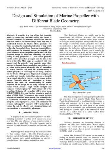
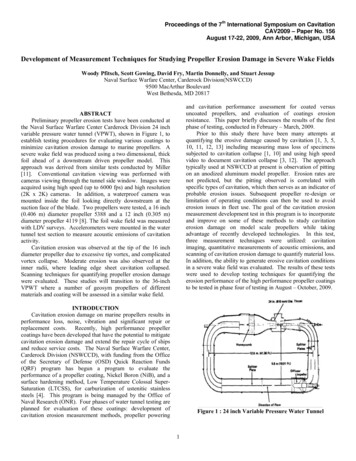
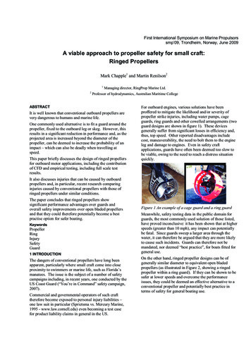
First International Symposium on Marine Propulsorssmp’09, Trondheim, Norway, June 2009 A viable approach to propeller safety for small craft:Ringed PropellersMark Chapple1 and Martin Renilson212Managing director, RingProp Marine Ltd.Professor of hydrodynamics, Australian Maritime College ABSTRACTIt is well known that conventional outboard propellers arevery dangerous to humans and marine life.One commonly used alternative is to fit a guard around thepropeller, fixed to the outboard leg or skeg. However, thisresults in a significant reduction in performance and, as theprojected area is increased beyond the diameter of thepropeller, can be deemed to increase the probability of animpact – which can also be deadly when travelling atspeed.This paper briefly discusses the design of ringed propellersfor outboard motor applications, including the contributionof CFD and empirical testing, including full scale testresults.For outboard engines, various solutions have beenproffered to mitigate the likelihood and/or severity ofpropeller strike injuries, including water pumps, cageguards, ring guards and other cowelled arrangements (twoguard designs are shown in figure 1). These devicesgenerally suffer from significant losses in efficiency and,thus, top speed. Other reported disadvantages includecost, maneuverability, the need to bolt them to the engineleg and damage to engines. Even in safety craftapplications, guards have often been deemed too slow tobe viable, owing to the need to reach a distress situationquickly.It also discusses injuries that can be caused by outboardpropellers and, in particular, recent research comparinginjuries caused by conventional propellers with those ofringed propellers under similar conditions.The paper concludes that ringed propellers showsignificant performance advantages over guards andoverall safety improvements over open bladed propellersand that they could therefore potentially become a bestpractise option for safer boating.KeywordsPropellerRingInjurySafetyGuard1 INTRODUCTIONThe dangers of conventional propellers have long beenapparent, particularly where small craft come into closeproximity to swimmers or marine life, such as Florida’smanatees. The issue is the subject of a number of safetycampaigns including, in recent years, one conducted by theUS Coast Guard (“You’re in Command” safety campaign,2007).Commercial and governmental operators of such crafttherefore become exposed to personal injury liabilities –one law suit in particular (Sprietsma vs. Mercury Marine,1995 - www.law.cornell.edu) even becoming a test casefor product liability claims in general in the US.Figure 1 An example of a cage guard and a ring guardMeanwhile, safety testing data in the public domain forguards, the most commonly used solution of those listed,have proved inconclusive: it has been shown that at higherspeeds (greater than 10 mph), any impact can potentiallybe fatal. Since guards sweep a larger area through thewater, it can therefore be argued that they are more likelyto cause such incidents. Guards can therefore not bemandated, nor deemed “best practice”, for boats fitted forgeneral use.On the other hand, ringed propeller designs can be ofgenerally similar diameter to equivalent open bladedpropellers (as illustrated in Figure 2, showing a ringedpropeller within a ring guard). If they can be shown to besafer at lower speeds and overcome the performanceissues, they could be deemed an effective alternative to aconventional propeller and potentially best practice interms of safety for general boating use.
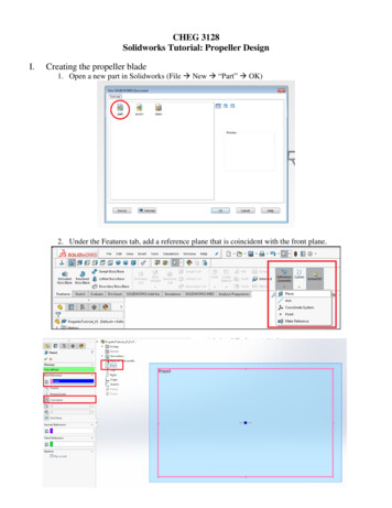
Figure 2 General schematic of ringed propeller andcomparison with diameter of a ring guard Ϯ KE Wd Ringed propellers, comprising a cylindrical or frustoconical ring attached to the tips of radial blades, haveexisted in various forms, if not been in common use, for atleast a hundred years. The purposes of such designs haveranged from protecting blades in shallow waters toattempting to improve efficiency. None of the historicaldevelopments to-date has enjoyed sustained use forvarious reasons, including performance detriment and highstress concentrations leading to failure.The specific propellers being dealt with here are one-piecedesigns (with integral hub, blades and ring) for use with,and retrofittable to, the common brands of outboard engine(see figure 3 ). The development began in the mid 1980s,incorporating cavitation tunnel testing at Marintek andQinetiQ, in the process, and has attempted to achieveperformance comparable to that of a conventionalpropeller.At the outset, it was assumed that improved safety,compared to open bladed propellers, would be definitivelyestablishable as required prior to commercialization.Specifically, the programme’s goal has been to achieveacceleration and top speed good enough to attract a viablemarket, whilst providing improved safety.Figure 3 Examples of modern ringed propellersϯ s KWD Ed ĂǀŝƚĂƚŝŽŶ ƚƵŶŶĞů ƚĞƐƚŝŶŐ The initial goal of the development work was to create aseries of propellers suitable for a range of outboard/boatcombinations. To do this it was first necessary tounderstand the broad influence of the principal features ofthe design, as applied across the horsepower range. Aseries of tests were commissioned at QinetiQ, Haslar,using a 2.4m x 1.2m cavitation tunnel. Two ringedpropellers and one conventional outboard motor propellerwere tested over a range of advance velocities andcavitation numbers, enabling information to be obtainedfor a number of different scales corresponding to differenthorsepowers. (Wiltshire and Miles, 2003).
to be logged simultaneously. Forward and reverse bollardpull tests were also conducted.To take into account changes in environmental conditionseach test program was repeated with a number of‘standard’ propellers, and the results calibrated.The test program required over 100 designs to bemanufactured: most of these were CNC milled from 3DCAD models (see image below) supplied from theMelbourne office, either from solid billet or near-net-shapeblanks cast using ureal moulds and some were tooled forlarger scale manufacture. (Figure 6).Figure 4 QinetiQ cavitation tunnel, Haslar, UKThe propellers had hub diameters corresponding to thethrough hub exhaust systems on modern outboard motors,and utilised a dummy nose cone. They were driven usingthe standard open water shaft dynamometer, and anoutboard leg was not simulated.These results gave confidence in the concept, and theopportunity to refine the basic geometry.Full scale testingAll subsequent hydrodynamic testing was done at fullscale using an instrumented boat in the National WaterSports Centre (NWSC) at Patterson Lakes, a suburb ofMelbourne in Victoria, Australia. This meant that actualresults applying to real boats could be obtained directly,and used to fine tune the propeller geometry for eachhorsepower range.The NWSC is an ideal location for testing as it comprises asheltered body of water of uniform depth over 2km longand 100m wide, with a convenient boat ramp. (See figure5).Figure 6 Ureal moulds for blank casting and prototypemachiningIn addition, testing was carried out with a variety of ringedpropellers in Michigan and Florida states in the USA on awider variety of craft and in different conditions toestablish wider performance benchmarks, including morequalitative tests such as ventilation and performance inweed-infested water.Computational Fluid DynamicsA Computational Fluid Dynamics (CFD) capability wasdeveloped in parallel with the full scale testing. Resultswere calibrated against previous empirical cavitationtunnel data as well as, more qualitatively, full scale testinformation. The analysis, although not predictingcavitation performance, proved able to guide developmentand rank designs, thus dramatically accelerating designiteration. Typical output is shown in figure 7Figure 5 Melbourne’s National Water Sports CentreA number of different boats were purchased to representsmall planing craft with lengths over the range of 14 to 26ft. A system of portable water tanks was developed tomake it easy to change the loading condition for each boat.Also, a number of different outboard motors with powersin the range of 8 to 225hp were purchased to represent allthe major outboard motor manufacturers. These were allreadily interchangeable on the different hulls to speed upthe testing process.A portable instrumentation package was developed toenable the boat speed (radar gun and GPS) and engine rpmFigure 7 CFD Data from development programmeϰ Z h d Performance testsFigures 8 and 9 show acceleration plots taken from testsconducted at Melbourne’s National Water Sports Centre
for two planning vessels, a RIB and an aluminium hulledboat, showing a direct comparison between a conventionalpropeller, a ringed propeller and a ring guard (Morley2006).Morley,Strykers Marine, 2005). The tests werepredominantly conducted using a variety of house boats.In both cases, the ring guard showed a reduction in speedof approximately 30%. The ringed propeller, however,showed a reduction of only 2.3% in the case of the RIB(50hp) and 8.8% in the case of the aluminium boat (90hp).These results are generally typical of similar tests carriedout in this programme, although other designs of guardwere not included.An engineering team from BEST (Biomechanical,Ergonomic and safety Technologies) was commissioned in2006. This organisation has expertise in engineeringsafety, injury prevention, biomechanics and human factorsincluding advice on personal injury liability as well asexperience in conducting tests relating to propeller guards(Kress 2006).The bollard pull results show very little difference betweenthe three configurations, both in forward and reverse. TheRPMs achieved are shown in table 1: for reverse bollardpull, in all configurations, the maximum thrust is achievedat a mid-throttle position due to ventilation as exhaustgases are drawn into the propeller disc.A facility and technical team was contracted at CRESE(Center for Research and Education in SpecialEnvironments) of the University of Buffalo, using andriven radial arm converted to carry a gantry, onto whichwas fitted a 50hp Honda outboard engine, around anannular water tank (figure 10). A remote actuator wasattached to the throttle such that both forward speed andengine revs could be controlled independently to simulatedifferent craft at different speeds.Safety testingFigure 8 Performance using 50HP Yamaha outboardFigure 10 CRESE annular tankSuitable target specimens were selected, including pigs,and these were tethered in front of a viewing window onthe side of the tank. High speed digital video was taken ofthe impacts and the target then removed for formalforensic examination and digital still images recorded. Asystematic series of tests, using a conventional aluminiumHonda propeller and an aluminium ringed propeller inpaired impacts, was undertaken to simulate low speedincidents (10mph and below).A test specimen is shown tethered prior to impact in figure11, as well as a tell-tale pattern of slices suffered byanother specimen caused by the conventional propeller.Table 1 Performance on 90HP Honda outboardIn testing in Michigan, it was found that entrapment inweed, and the ensuing ventilation caused, was significantlyless severe for the ringed propeller than for theconventional propeller being tested (Chapple,BEST found that: “Experimental date indicated that if ahuman is impacted at low speeds, i.e. below approximately10 mph, the [ringed] propeller causes less soft tissue andbone damage than a standard propeller. In some instances,the comparison between the soft tissue and bone injuriesresulting from an impact by a [ringed] propeller verses astandard propeller may mean the difference between lifeand death, respectively.” (Kress, 2006)
ZĞĨĞƌĞŶĐĞƐ Chapple, Morley,Strykers Marine, Edenville Michigan,September 2005: series of performance tests conductedwith displacement craft.Kress,Tyler A., January 2006: study of injuries caused byopen bladed and ringed propellers conducted at CRESEfacility at State University of New York, Buffalo, USA.Kress, Tyler A. and Reid L. Kress (USA) Paper #387-022,July 2003, presented to IASTED International Conferenceon Biomechanics, Rhodes, Greece: focuses oneffectiveness of propeller guards by applying fault treeanalysis techniques and encourages further study to collectdata on injury severity and frequency.Milligan, MW, and Tennant, JS, 1998, Propeller injuryprotection, an evaluation of commercially availableprotection devices, A report of the Marine TechnologicalSociety, Prepared for the Office of Boating Safety, UnitedStates Coast Guard, October 1998.Morley, 2006: Speed testing in Patterson Lakes (NationalWater Sports Centre) using radar and GPS.Figure 11 test specimen before and after impactϱ KE h /E' KDD Ed The performance of the ringed propellers tested, in termsof speed (and efficiency), show a significant improvementover that of the guards tested. Also, the performancedeficit compared to conventional propellers may be smallenough to represent a viable alternative for a largeproportion of boat users.In addition, it appears that the relative safety has beenestablished for low speed accidents while there are noarguments known by the authors to suggest that ringedpropellers should be more dangerous than conventionalpropellers at higher speeds.The combination of these two points, together with theease of retrofitting to existing installations, couldpotentially establish the ringed propeller as a best practiceoption for safer boating. Sprietsma, Mecury : Rex R.Sprietsma, administrator of the estate of Jeanne SP,petitioner v. Mercury Marine, a division of BrunswickCorporationon writ of certiorari to the supreme court ofIllinoisUS Coast Guard, 2006: www.uscgboating.org - “You’re inCommand”, a boating safety campaign undertaken by theUS Coast Guard in 2007 to highlight the dangers ofpropeller strike.Wiltshire, JR, and Miles, S, 2003, RingProp propellertests at QinetiQ, Haslar, QinetiQ report:FST/CRo33042/1.0, June 2003
propeller, a ringed propeller and a ring guard (Morley 2006). In both cases, the ring guard showed a reduction in speed of approximately 30%. The ringed propeller, however, showed a reduction of only 2.3% in the case of the RIB (50hp) and 8.8% in the case of the aluminium boat (90hp). These results are generally typical of similar tests carried