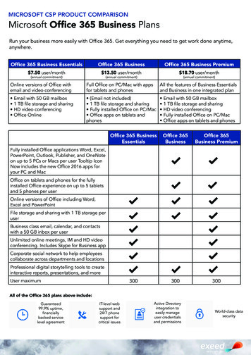
Transcription
OFFICE DELIUSER AND SERVICE MANUALRev. 2013.08.191
OFFICE DELI SPECIFICATIONSThe OFFICE DELI is comprised of three (3) units - Snack Unit (OD16S), Beverage Unit (OD8RD) andEntrée Unit (OD14F). Installation and setup of these units is explained in the next sections of thismanual.Machine DescriptionSnack UnitBeverage Unit Entrée UnitModel NumberOD16SOD8RDOD14FHeight (in)28.54169.5Width (in)30.230.212.2Depth (in)28.528.528.5Volts (V)115115115Frequency (Hz)606060Watts (W)6036060Current (A)*0.53.00.5* - Current draw varies depending on Operating Conditions and Load and are subject to change.The OFFICE DELI is designed for use in indoor conditions only. Therecommended operating environment is 75 F and 40% RH.Rev. 2013.08.192
OVERVIEWThis manual covers Installation, Setup, Programming and Service instructions. It is extremelyimportant that this manual be read thoroughly prior to commissioning the OFFICE DELI unit in thefield. This will ensure a satisfactory long-term performance.The OFFICE DELI unit consists of three (3) separate cabinets that are installed together viamechanical means and connected via electrical connections to operate as ONE unit.The Snack Vendor (OD16S) consists of three (3) trays. The first and second trays have 4 selectionseach (Tray 1 – B1 through B4, Tray 2 – B5 through B8). The third tray has 8 selections (C1 throughC8). The top two trays are normally used for products that are wider such as chips, pastries etc. andthe third tray is used for Confectionary items such as candy bars. The Snack Vendor (OD16S) alsohouses all the payment mechanisms and electronic Vending Machine Controller (VMC) on the rightside of the cabinet, as shown in Figure 19. The payment mechanisms, electronic components (suchas VMC) and transformer are installed on a vertical shelf that slides out for easy access. Theconnectors to connect the Beverage Unit (OD8RD) and Entrée Unit (OD14F) are also provided in thisvertical shelf of the Snack Vendor (OD16S).The Beverage Vendor (OD8RD) consists of Product Delivery systems consisting of a teeter-totterstyle mechanism and a vertical drop system. The Beverage Vendor also houses the removableRefrigeration System. The cabinet of the Beverage Vendor has a delivery system that has 6selections for Cans and 2 selections for Bottles. The Cans are loaded in the chutes (D1, D2, D3, D4,D5 and D8) and the Bottles are loaded in Vertical Drop System columns (D6 & D7). The loadinginstructions are given in subsequent sections. The refrigeration system is installed at the bottom ofthe Beverage Vendor and there is a foamed separation between the cabinet interior and therefrigeration system. The installation, setup and functionality of the refrigeration system is explainedin the section titled Refrigeration.The Entrée Unit (OD14F) consists of 7 trays with 2 selections each (Tray 1 – A1 & A2, Tray 2 – A3 &A4, Tray 3 – A5 & A6, Tray 4 – A7 & A8, Tray 5 – A9 & A10, Tray 6 – B9 & B10, Tray 7 – C9 & C10).RECEIVING, INSPECTION, UNPACKING AND TESTINGAfter you have received your Office Deli, inspect all three individual vendor components. Note: Anydamages that may have occurred during shipping must be reported to the delivery carrierimmediately. Reporting damages and the seeking of restitution is the responsibility of the equipmentowner. The factory is willing to assist you in this process in any way possible. Feel free to contactSeaga Customer Care with questions you may have on this process. Once you have your Office Delilocated, we suggest that you keep this manual for future reference.The Office Deli Unit is placed on a wooden pallet and stretch-wrapped. Please exercise caution whilecutting into the stretch-wrap with a sharp tool such as a utility knife, as it may cause scratch marks onthe machine.The Snack, Beverage and Entrée Units are boxed in three (3) separate cardboard boxes. The SnackUnit box is placed on top of the Beverage Unit while the Entrée Unit is located on the side ofSnack/Beverage Units. After removing the stretch wrap, remove the Snack Unit and place it aside.USE EXTREME CAUTION AS THE TOP OF THE BOX IS NOT ATTACHED TO THE BOTTOM OFTHE BOX. The top of both the snack and beverage units slide up for removal. Remove the BeverageUnit from its box and place it in the desired vending location. Remove the Snack Unit from its box andplace it on top of the Beverage Unit carefully. Please use proper lifting and safety precautions whileplacing the Snack Unit on top of Beverage Unit. Remove the Entrée Unit from its box and place it tothe left side of the Snack/Beverage Units.Rev. 2013.08.193
Open all Unit doors and remove the packing materials. Keys can be found in the white envelopeplaced in the vend area of the Snack Unit. Remove the tape on the tray levers of the Snack andEntrée units. Also remove the protective paper from under each helix coil as well as ties securing theends of the helix coils during shipping. Remove all protective plastic from the window lenses.Remember: at least two people are necessary to move any of the components of the Office Deli.Follow proper safety standard for lifting and working with electronic/refrigerated equipment.INSTALLATION AT A LOCATIONOnce the machines have been unpacked and placed in their permanent location, installation involvesboth electrical connection and mechanical attachment. Tools required: Adjustable wrench and Philipsscrewdriver. For optimal installation, follow the order of connections as outlined below:1. Mechanical Connection between Snack and Beverage Units:The Snack and Beverage units must be screwed together for safety purposes. Two screwsare provided in the white envelope found in the vend area of the Snack unit. Square thefronts and sides of the Snack and Beverage units. Open the Snack unit door and locate thetwo holes at the bottom of the unit. Insert both screws and tighten.2. Mechanical Connection between Entrée Unit and Snack/Beverage Unit:Two bolts and washers are provided in the white envelope found in the vend area of theSnack unit. Open the Entrée unit door and locate the two holes (upper and lower) on theinterior of the right side of the unit. Line up the holes with the corresponding holes in theSnack/Beverage unit. Insert the bolts and washers and tighten with an adjustable wrench.3. Electrical Connection between Snack and Beverage Units:Remove the Styrofoam insert from the opening in the upper right corner of the beverage unitand save this for reinsertion. Open the Beverage unit door and locate the beverage mainharness and refrigeration harnesses. See Figure 1. Insert harnesses through the opening upinto the Snack cabinet, see Figure 2. Reinsert the Styrofoam piece for maximum insulation ofthe refrigeration unit. (You may have to remove a small piece out of the Styrofoam toaccommodate the harnesses.)Figure 1 – Beverage and Refrigeration HarnessesFigure 2 – Inserting Beverage andRefrigeration HarnessesBeverage arnessesinserted upthroughSnack UnitConnect the beverage main harness to Connector #5 and connect the refrigeration harnesses tothe “Aux” connection on the VMC. Use an adjustable wrench to loosen the ground mounting nutand install the ground. Secure the nut back on the ground mounting, taking care not to overtighten. See Figure 3.Rev. 2013.08.194
Figure 3 – Making Beverage ConnectionsRefrigeration harness plugs into AUXconnection.Install ground wire ring terminal onthe mounting stud. Remove nut withadjustable wrench; replace to secureground wire.Entrée main harness attaches toConnector #4.Beverage main harness attaches toConnector #5.4. Electrical Connection between Entrée Unit and Snack/Beverage Unit:Remove the third tray from the Entrée unit, by flipping up the tray lever (found on the rightside of the tray), disconnecting the tray connector harness, and removing the tray from theunit. A hole in the rear of the Entrée unit will be exposed. Locate the entrée main harnessand insert it through the hole. Replace the third tray. Move to the rear of the machine andinsert the entrée main harness into the back of the Snack Unit. The harness will bedeposited into the Snack cabinet. Connect the harness to Connector #4. See Figure 3 for thelocation of Connector #4.After finishing the connections, plug the two main power cords to 115V, 15 A outlets. Theoutlets should not be controlled by a light switch. Once power is established, the LED displaywill first read Software Version and then change to “00.00”. The refrigeration system will alsostart running (fans followed by compressor after short delay).Rev. 2013.08.195
Figure 4 – Connecting the Snack, Beverage & Entrée UnitsFigure 5 – Connecting the Snack, Beverage & Entrée UnitsInsert the entréemain harness intothe openinglocated in the rearof the Snack unit.Plug both blackpower cordsinto wall outletsLOADING PRODUCT TRAYSOpen the front door of vendor, and lift up the plastic lock lever on the right side of the tray to unlock.Holding the lever up, grasp the tray and lift the front of the tray slightly and pull forward. The tray willslide out and then tilt down to make loading of products easier. Load only one product tray at a time(See Figure 6).Rev. 2013.08.196
Figure 6 – Slide-out product traysLift up plastic lockleverGrasp traywhileholding uplever andpullforward1. To Load Product in Snack Unit and/or Entrée Unit:a. Pull the desired product tray all the way forward. Product tray will tilt down.Note: Pull out only one (1) product tray at a timeb. Place product in proper size helix coil.Note: Bottom of product must rest on the product tray and not on theHelix Coil. Load each column from back to front.Note: Fill all product trays fully; do not leave any spaces behind or between itemsc. Once product tray is fully loaded, lift and push it back in.Repeat steps a through c until all product trays are fully loaded. Special Note: We suggest that youalways partially fill the tray with product and perform at least five (5) test vends. Test vends can beperformed easily by entering Service Mode and running the “tE” function -Individual motors testing.PRODUCT LOADINGSnack UnitWide products such as Chips bags etc. are loaded in Tray 1 and Tray 2. Narrow products such asCandy bars are loaded in Tray 3. See Figures 7a and 7b.Figure 7a – Loading ProductIncorrectCorrect – loadproduct betweencoils, resting onthe product tray,never on thebottom loop ofthe coil.CoilProduct TrayRev. 2013.08.197
Figure 7b – Loading ProductIncorrectIncorrectCorrect – load product between coils,resting on the product tray.HELIX COIL LOCATION ADJUSTMENTIf you are required by a location to vend a product that is not on your Plan-O-Gram, you may need toorder a different helix coil and install it. To replace a helix coil:1. Remove the Helix Coil from the Coil Driver by lifting the back of the helix coil up off the coildriver. You will need to move the bottom of the helix coil clear of the coil driver to completelyremove the helix coil. See Figure 8.2. Align the new helix coil end with the front of the tray, which gives the helix coil better contactwith the product. The position of the helix coil in the coil driver is adjustable to assist you inaligning the new helix coil at the front of the tray. See Figure 8.This Coil adjustment can be done for all the Selections on Snack and Entrée units.Figure 8 – Removing and Aligning a Helix CoilLift Helix CoilBack of ProductTray, Snack orEntréeMove bottom ofHelix Coil to clearCoil Driver andremoveRev. 2013.08.19Helix Coil Driverwith 5 adjustmentoptions8
Beverage UnitThe cans are loaded in D1, D2, D3, D4, D5 & D8. Selections D6 & D7 can be loaded with bottles.These instructions are also available for quick reference on a yellow decal inside the unit. See Figure9.Figure 9 – Loading Beverage UnitProduct ChutesSelections D1, D2 and D3There are two chutes for each selection.1. Load 2 cans only into the bottom chute.2. Load cans into the top chute untilcompletely full. Upon filling top chute,proceed to fill bottom chute, leaving one less canin this chute. This assists with the gravity methodof vending.Selections D4, D5, D8stChute #1 Vends 1ndChute #2 Vends 2Selections D1, D2, D3stChute #3 Vends 1ndChute #4 Vends 2Selections D4, D5 and D8There are two chutes for each selection.1. Load 5 cans only into the bottom chute.2. Load cans into the top chute until completely full.Upon filling top chute, proceed to fill bottom chute.Vertical Product ColumnSelections D6 and D7Vertical Product Columns1.) For bottles, place cap of the first bottle against the frontof the column depressing the Sold Out Switch. Place thesecond bottle to the rear of the column, touching the bottomof the first bottle. See illustration at right.2.) Finish loading to the top of the column, making surebottles are perfectly horizontal and not tilted or skewed inthe column.3.) To adjust the rear spacer, grasp firmly and lift up andmove forward or rear, as required, so that the rear spacer istouching the rear bottle.Note: There are many variations of packaging among thebeverage brands. The instructions above are meant to be aguideline. If you have packaging that isn't mentioned orshown, experimentation will be necessary for a proper vend.Rev. 2013.08.199
Figure 10 – Vertical Column ComponentsRear spacer positionfor 16.9 oz. bottles(20th slot)You may need to adjust due to product height variance.Rear SpacerBottle Cam showninstalled on auger.Motor andbrackets removed.Rev. 2013.08.1910
SizeTypeRearSpacerMaxLoadCoca-Cola and varietiesPepsi, Diet Pepsi, Mt. Dew andvarieties16.9 oz/500 mlBottle2014Load bottom to bottom16.9 oz/500 mlBottle2014Load bottom to bottom7 up and Diet 7up16.9 oz/500 mlBottle1914Load bottom to bottomDr Pepper, Diet and varieties16.9 oz/500 mlBottle1914Gatorade16.9 oz/500 ml1612Nestle Water16.9 oz/500 mlBottleBottle(soft)Load bottom to bottomKit available fromparts@seagamfg.com1620Monster, Rock Star, etc.16.9 oz/500 mlCan814Coca-Cola and varieties12 oz/355 ml1021FrappuccinoRed Bull, Starbucks DoubleShotCoca-Cola and varieties, Pepsi,Mt. Dew, etc.9.5 oz/281 mlCanBottle(glass)nana8.4 oz/248 mlCan**24 oz/710 mlBottlenanaProductNotesLoad bottom to bottomKit available fromparts@seagamfg.comKit available fromparts@seagamfg.comDo not vendKit available fromparts@seagamfg.comDo not vendBottle Shim shown InstalledBottle ShimFigure 11 – Removing Vertical Drop Motors and Auger SystemRemove auger forreplacement.Remove twoscrews holding inmotor/bracket.If replacing motor,unplug wireharness andre-assemble.If replacing auger,continue withinstruction toright The Beverage unit does not ensure FIFO (first in first out). So whenever fresh beverages are loaded(usually from the upper chutes) it is likely that the lower chutes of the can unit may still be holdingsome older cans for a period of time. Although beverages have reasonably good shelf life, werecommend that the Beverage unit be emptied once every 30 days and reloaded, so that a forcedproduct rotation takes place.Rev. 2013.08.1911
Entrée UnitThe appropriate loading procedure is dependent on the type of product you will be vending, as entréeitems have different sizes and shapes.Note: The size of the item being vended must be larger than the Helix Coil, but smaller than thecolumn, to vend correctly. Never force an oversized item into the helix coil or column, nor attempt tovend an item that is smaller than the helix coil as this will create problems and deter customers.To present your product in as attractive and professional manner as possible, do not load damageditems and make sure that the items are facing forward for easy identification by your customer.Depending on shape of product, the orientation in the helix coil may change for best fit.ENTRÉE UNIT TRAY ADJUSTMENTEntrée Unit trays are provided with width adjustment for each selection. To adjust the width of aselection in your Entrée Unit:1. There are three (3) holes on the front of the tray for the Divider fastener and three (3)rectangular openings on the back of the Tray for Divider positioning as shown in Figure 12.2. Place the product in the Coil for reference and adjust the Divider to support the new productand line up the mounting hole. Products should not fit too tightly in the column. The productshould not be touching the divider when placed in ready-to-vend position in Helix Coil.3. Once the location of Divider is determined, line up the end tab on the Divider with therectangular opening on the back of the tray as shown in Figure 12.4. Complete the installation by securing the front of the Divider with a fastener in the mountinghole. See Figure 12.Figure 12 – Entrée Unit DividerThree rectangular openingsDividerThree fastener holesNote: This adjustment will result in reduction of width in the adjacent selection. Please make surethe product to be vended from the adjacent selection is appropriately placed as per loadinginstructions as described in “Product Loading” section.Rev. 2013.08.1912
KEYPAD AND LED DISPLAYThe Keypad is touch sensitive. Light pressure will be necessary to activate each number or letter. TheKeypad is used by the customer to make their selection, and by the operator to set and test manyfunctions of the Office Deli. Note: The keypad and LED Display are 2 separate components, thoughthey appear as one streamlined piece.Figure 13 - KeypadWhen LED is oncheck price and theninsert coinsWhen LED is onInsert exact changeonly for a vendLED DisplayWhen LED is on thecustomer mustchoose alternateselectionPrevious inService ModeAlso displaysbeveragecompartmenttemperature instandard modeNext inServiceModeThe LED Display shows the customer the amount of money entered into the vendor, and the cost oftheir selection. It shows the operator the Service Mode function for setting and testing the variousfunctions of the vendor.PROGRAMMINGUnlock and open the Front Door to access the VMC, and enter Service Mode by pressing theMENUS Button. (Fig. 14)Figure 14 - MENUS ButtonShelf SelectionHarnessMotors HomeHarnessDisplay HarnessMENUSButtonRefrigerationHarness (AUX)Keypad HarnessPayment SystemsHarnessGround Mounting24 V PowerHarnessRev. 2013.08.1913
BASIC OPERATIONThe following display formats are used:Display whenActiveStandard Operation, no credit available00.00Standard Operation, some credit available00.01 – 99.95After Pressing a selection, if there is no credit, orthe credit is less than the selection’s price, theprice of the selection is displayed for a fewseconds, before reverting to one of the abovecredit display formats.(If a coin or other payment is made, the displayreverts immediately)00.05 – 99.95Free Vend Mode (all prices set to zero)FrEEIf a selection is out of stock when a selection ispressed – this is displayed for a few secondsSold Out(as two successivemessages)All Items out of stockSold Out(as two successivemessagesrepeated)Out oF Ordr(as 3 successivemessages)Machine Out Of OrderDuring a Vend (Progress bar, 1, 2, 3 and 4dashes)----Consumer presses Coin Return when ForceVend is ON, change is not permittedSELExact Change required (MDB Changer enabled)Temperature Display (if control is enabled) –press the 10 button to displayTimed Lockout or H & S lockoutRefrigeration System Error: Note Error Code 70in Error Codes section of this manual.Rev. 2013.08.1914ExactLEDOFFErrtALTSELLEDONONONnnC or nnFCheckPriceLED
SERVICE MODEThe operation of the machine can be adjusted by entering Service Mode, pressing the MENUSbutton on the VMC circuit board and accessing the appropriate operation. Price setting, auditdisplay and operating modes can be read and adjusted from here. The user can also perform testson the machine through this mode. Note: any Credit will be cancelled on entry to Service Mode.1. Enter Service Mode by pressing the MENUS Button on the VMC Circuit board.2. Each Service Code can then be accessed using the 9 (Next) and 10 (Previous) buttons toscroll through the menus in sequence:1. AUDITDisplaysAu.--2. PRICE SETTINGDisplaysPS.--3. TEST MODEDisplaystE.--4. CONTROL WORDDisplaysCt.**W here ** is the current value5. SOUND On/OffDisplaysSo.0*W here * is the current state (0 or 1)6. DISPLAY ERRORSDisplaysEr.--7. CLEAR ERRORSDisplaysCE.--8. SET CLOCKDisplaysCL.--9. MDB PAYMENT DEVICESDisplaysPd.**W here ** is the current value10. HOME & COUNT MOTORSDisplaysHo.**W here ** is the last count of motors11. TEMPERATURE SETTINGDisplaystS.**Where ** is the current state12. END MENUSDisplaysEn. --AUDITWithin Service Code Au (Audit) readings can be taken from the Display with regards to cash taken,and number of products vended. The following details can be obtained on the lTotalCash IN : (up to 999999.99)Product Sales Value: (up to 999999.99)Count of Free Vend Tokens : (up to 49999)Coins IN : (up to 999999.99)Cash Out : (up to 999999.99)Bills IN : (up to 999999.99)Card Payment : (up to 999999.99)Manual Dispensed amount: (up to 999999.99)Selection (alpha then numeric)Display the total number of individual vends of that selection (up to 49999)Press the Scroll buttons (9 and 10) repeatedly until the LCD Displays Au.You are now in Audit ModePress Selection Button 2 to reveal the total sales valueDisplays **** and **.** Etc.Values are displayed in parts as **** then **.** for values up to 999999.99and ** then **** for non decimal values up to 49999.Rev. 2013.08.1915
Note:Decimal values “roll-over” from 999999.99 to 0.00Integer counts “roll-over” from 49999 to 0NOTE: FOR SECURITY PURPOSES, TOTALS DO NOT ZERO OUT AFTER EACH TIME YOUDISPLAY TOTALS.PRICE SETTINGPrice Setting is performed by selecting Service Code PS.1. Press the Scroll buttons (9 and 10) repeatedly until the LCDDisplaysPS.--You are now in Price Setting Mode2. Make a selection (Alpha then number) to display the current priceDisplays the row and column and then **. **3. Using the numeric keys, set the price for this selection (the 10 button is interpreted as azero) by entering 4 digits. The display will then revert to PS when this is complete.Prices may be set from 00.00 to 99.95.4. Press two Alpha selections (Ex: “A” then “A”) then a number (price) to set the price foran entire tray at once. Pressing three Alpha selections (AAA) allows all the prices to beset in one operation.TEST MODE1. Press the scroll buttons (9 and 10) repeatedly untilDisplaystE.- -In Test Mode, making a selection (Alpha then numeric) will operate the selected motor.PressPressPressPressselection buttonselection buttonselection buttonselection button1 for a single test vend on ALL selections.2 to test the positive vend sensor (if enabled).3 to test Relay output 1 (Compressor Cycle).4 to test Relay output 2 (Defrost).Note : You must be in Test mode to manually empty the coin changer.WARNING : THIS MENU OPTION DOES NOT TIME OUT AFTER 30 SECONDSCONTROL WORD1. Press the Scroll buttons (9 and 10) repeatedly until the LCD(where ** is current value)You are now in Control Word SettingDisplaysCt. **2. Press Selection Button 1 to 4 to change the control wordDisplaysCt.**The control word is now set***RECOMMENDED CODE:Rev. 2013.08.19216
The control word options supported are :Code1234MultivendNo – single vendYes - multivendNo – single vendYes - multivendForced VendNoNoYesYesSOUND (ON/OFF)1. Press the scroll buttons (9 and 10) repeatedly untilDisplaysSo.002. Press Selection Button 1 to toggle the settingDisplaysSo.01DisplaysEr.- -3. Press any other Button to exit to the next menu optionA value of 1 enables the sound, 0 disables the sound.***RECOMMENDED CODE:1 (ON)DISPLAY ERRORS1. Press the scroll buttons (9 and 10) repeatedly untilIn this mode, press any selection button (other than 9 or 10) to display error codes in sequence,shown as Er.nn where nn is the error number.ERROR CODESError CodeNumber01 . 60Fault detectedHard/SoftfaultActionMotor A1 . F10 respectivelySoftRepair/replace motor/home switch70Refrigeration ErrorHard80Coin Changer faultHard818285Changegiver Out Of ChangeError in credit valueMDB Bill Reader faultSoftSoftHard90MDB Card Reader faultHard91Error in Bill credit valueSoftCheck connection to temperaturesensor, check connection to AuxTerminal on main control boardRepair/replace coin changer ordisable the coin changerFill TubesNoneRepair/replace Bill Reader or disablethe bill readerRepair/replace Card Reader ordisable the Card readerNoneSoft Errors – unit will continue to operate though failed motors will show as “Sold Out” and beblocked from operation if selected.Hard Errors – the unit is put out of service. This mode can only be cleared via the menus.CLEAR ERRORS1. Press the scroll buttons (9 and 10) repeatedly untilDisplaysCE.- -In this mode, press any selection button (other than 9 or 10) to clear all errors – confirmed with a“CLr” display.Rev. 2013.08.1917
SET CLOCK1. Press the scroll buttons (9 and 10) repeatedly untilDisplaysCL.- -In this mode, press the selection buttons listed below to set the current time, date and day of week:1. Time – displayed in a 24-hour clock format as HH.MM Press 4 digits in turn to set thetime.2. Date – displayed as DD.MM Press 4 digits in turn to set the date and month.3. Year – displayed as y-YY Press 2 digits in turn to set the year (00 – 99).4. Day of Week – displayed as d-- n enter a single digit to set the day of week (1 Sunday, 2 Monday 7 Saturday)In this mode, press the selection buttons listed below to set the unit Serial Number and AssetNumber (4 digits only):A Asset Number : Press 4 digits in turn to set the value.BSerial Number : Press 4 digits in turn to set the value.MDB PAYMENT DEVICES1. Press the scroll buttons (9 and 10) repeatedly until(where ** is current value)You are now in Payment Device SettingDisplaysPd. **2. Press a numeric selection (1 – 7) to change the valueDisplaysPd. **The Payment Device code is now set***RECOMMENDED CODE:3The payment device values supported are :Value12345678Coin ChangerONOFFONOFFONOFFONOFFBill ValidatorOFFONONOFFOFFONONOFFCard ReaderOFFOFFOFFONONONONOFFHOME AND COUNT MOTORS1. Press the scroll buttons (9 and 10) repeatedly untilDisplaysHo.nnIn this mode, press and key other than 9 or 10 to home and count the Motors. The LED display willshow the row/column being homed, and each motor will activate in sequence – each helix coil willturn and each can and bottle motor will rotate. If products are loaded, one of each product will bevended. If the circuit board is reading the motors correctly, a cumulative count of motors isdisplayed on the LED. If there is a circuit/motor problem on a particular selection, “Err” will appearon the LED after each faulty selection number.Rev. 2013.08.1918
IMPORTANT: THE MOTOR HOME AND COUNT FUNCTION SHOULD NEVER BE USED WHENPRODUCTS ARE LOADED AND THE DOORS ARE CLOSED. ALL SELECTIONS WILL VENDIN SEQUENCE AND SERIOUS PRODUCT JAMS WILL OCCUR.TEMPERATURE SETTINGS1. Press the scroll buttons (9 and 10) repeatedly untilDisplaystS.**** shows the current stateThis menu option allows the zone temperature settings to be displayed and modified.The first digit is the ON/OFF state: 0 means that the zone control is OFF1 means that it is ONThe second digit shows the temperature scale currently in use:F means FahrenheitC means CelsiusExamples:tS.1FZone control is ON, temperatures in FahrenheittS.1CZone control is ON, temperatures in CelsiustS.0FZone control is OFF, temperatures in FahrenheitIn this mode, press the selection buttons listed below to set mode and temperature limits1Turn the Zone ON.2Turn the Zone OFF.3Set the LOWER Limit control temperature - Press 2 digits in turn to setthe temperature (00 - 99). Any other alpha key will cancel the operation.Lower limit - minimum 1 C (34F) maximum 11 C (53 F).4Set the UPPER Limit control temperature - Press 2 digits in turn to setthe temperature (00 – 99). Any other alpha key will cancel the operation.Upper Limit - minimum 3 C (37 F) maximum 13 C (56 F). Upper limitto be set at least 2 C above the lower limit.5Select Celsius (Centigrade) temperature display.6Select Fahrenheit temperature display.END MENUS DISPLAYEND MenusDisplays En.--Exit Service Mode by selecting the END option and press any key other than 9 or 10, or the menusfunction will end automatically if there is no activity for 30 seconds.Rev. 2013.08.1919
REMOVING PRODUCT TRAYPush up the plastic cam lock lever on the right side of tray (Fig. 15). Grasp the Product tray underboth the front corners, and lift the front of the tray slightly and pull the tray out completely. Removethe Wiring harness connecter located on the inside right-hand side of the tray.Figure 15 – Product tray cam lock lever(Shown with tray removed)CamLockLeverVEND MOTORSEach Selection is vended by the action of the Vend Motor. The Vend Motors are screwed onto therear of each Product Tray. In the rare event of a jam, a Vend Motor may need to be returned to itshome position.Figure 16 – Vend Motor2 screwshold motorto trayMotorHarness1. To “Home “ a Vend Motora. Unlock and open the Front Door to access the Circuit Board, and enter Service Modeby pressing the MENUS Buttonb. Cycle through the Service Mode until the Display Reads “tE”c. Enter the letter and number of the motor you wish to home. The motor will rotate toits home position.2. To Remove a Vend Motora. Unlock and open the front doorb. Unlock Product Tray and pull it out fully while keeping it levelc. Lift Product tray to release from the Track and pull it outCaution: The Product Tray Wire Harness will need to be unplugged prior to complete removal of theproduct tray. The wiring harness is plugged into the slide-out shelf in the Snack unit.d. Remove Helix Coil from the driver by lifting the front end of the Helix Coil up withone hand pinching the lugs of the shaft. Push the shaft through the back of the vendmotor, freeing up the helix coil/driver/shaft assembly for removal.Note: This operation is more difficult with smaller Helix Coils.e. Remove the two Phillips head screws that are
cutting into the stretch-wrap with a sharp tool such as a utility knife, as it may cause scratch marks on the machine. The Snack, Beverage and Entrée Units are boxed in three (3) separate cardboard boxes. The Snack Unit box is placed on top of the Beverage Unit while the Entrée Unit is located on the side of Snack/Beverage Units.


![Office 2010 Professional Plus Com Ativador Serial Keyl [EXCLUSIVE]](/img/61/office-2010-professional-plus-com-ativador-serial-keyl-exclusive.jpg)