Transcription
KVH Industries, Inc.TracVision RV1 Installation Guide
TracVision RV1 Installation GuideThis guide explains how to install the TracVision RV1 satellite TV antenna system on a vehicle.Operation instructions are provided in the Quick Start Guide.Installation Steps1. Inspect Parts and Get Tools . 310. Connect Power . 162. Plan the Antenna Installation . 411. Turn On the System. 183. Plan the TV-Hub Installation . 512. Access the Web Interface . 194. Prepare the Antenna Site. 613. Connect to an Existing Network . 205. Wire the Antenna . 714. Secure the Wi-Fi Connection. 216. Mount the Antenna . 815. Set Up the System . 227. Mount the TV-Hub. 916. Set the LNB Skew Angle. 258. Wire the Antenna to the TV-Hub. 1017. Educate the Customer. 269. Wire the Receivers. 11AppendicesA. Installing an IP AutoSwitch . 27B. Using a DIRECTV Coax Network. 30Who Should Install the System?To ensure a safe and effective installation, KVH recommends that a KVH-authorized technicianinstall the TracVision antenna. KVH-authorized technicians have the tools and electronicsexpertise necessary to install the system.KVH, TracVision, and the unique light-colored dome with dark contrasting baseplate are registered trademarks ofKVH Industries, Inc. All other trademarks are property of their respective companies. The information in this document is subjectto change without notice. No company shall be liable for errors contained herein. 2014 KVH Industries, Inc., All rights reserved.54-0969 Rev. B1
Important Safety InformationThis icon indicates a danger, warning, or caution notice. Be sure to read these carefully to avoidinjury.WARNINGRisk of Electric ShockTo avoid electric shock, do not open the TV-Hub chassis enclosure. There are no user-serviceable partsinside.WARNINGRisk of Electric ShockIf any component of the TracVision system becomes damaged and/or no longer functions normally,disconnect it from vehicle power, secure it from unintended operation, and contact KVH TechnicalSupport (see “Technical Support” on page 1). All repairs or modifications must be performed by atrained, KVH-certified technician. If you are a KVH-certified technician, you still must contact KVHTechnical Support prior to conducting any repairs or modifications to the equipment.WARNINGRisk of ExplosionDo not operate the TV-Hub (or any other electrical device) in an environment where flammable gases,vapors, or dusts are present. In addition, do not operate the TV-Hub in an environment with atemperature outside its 5º F to 131º F (-15º C to 55º C) temperature range.WARNINGRisk of Electric ShockFailure to ground the TracVision system properly to the vehicle’s ground will cause an unsafe floatingground condition, risking potentially lethal electric shock. See “Connect Power” on page 16 for detailson the proper grounding of the equipment.CAUTIONRisk of BurnsMake sure the antenna is pointed away from the sun whenever the radome is removed. The high-glossreflector can focus sunlight into a narrow beam, generating a significant amount of heat that can causedamage and injury.2
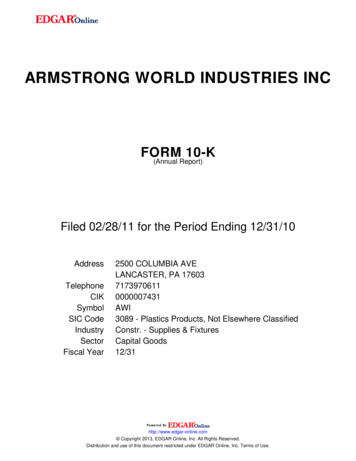
1Inspect Parts and Get ToolsBefore you begin, follow these steps to ensureyou have everything needed to complete theinstallation.Figure 1: TracVision RV1 System ComponentsAntennaIMPORTANT!Always lift the antenna by the baseplate andnever by the radome or any portion of theinternal antenna assembly (see Figure 1).RadomeBaseplatea. Unpack the box and ensure it containseverything shown on the Kitpack ContentsList. Save the packaging for future use.b. Carefully examine all of the supplied parts toensure nothing was damaged in shipment.TV-Hubc. Gather the tools and materials listed below.You will need these items to complete theinstallation. Flat-head and Phillips screwdrivers Adhesive tape and scriber or pencil Light hammer and center punch 5/8" (16 mm) hole saw Electric drill and 1/8" drill bit Construction adhesive and fastenerssuitable for mounting the antenna tothe roof 7/16" open-end wrenchDIRECTV*DISH Network* 7/16" open-end torque wrenches set to20 in.-lbs (2.25 N-m) and 15 in.-lbs(1.7 N-m) Silicone sealant or equivalent311211211k211z Torque wrench and 2 mm Allen hex key(linear system only)H20H21H22H23H24H25HR21, HR21 ProHR22HR23HR24HR34HR44 Satellite TV receiver(s)/DVRs foryour desired service (see Figure 2). Wi-Fi-enabled laptop PC with thelatest TracVision software andsatellite library downloaded from theKVH Partner Portal (www.kvh.com/partners), or Apple iOS or Android smartphone/tablet with the latestdownloads via the TracVision TV/RVmobile appFigure 2: KVH-Validated ReceiversLinearFor information on the recommendedreceivers for linear service, contact your localKVH dealer/distributor.Bell TV*610061316400* List is subject to change. For information onconnecting different receiver models, contact KVHTechnical Support.3
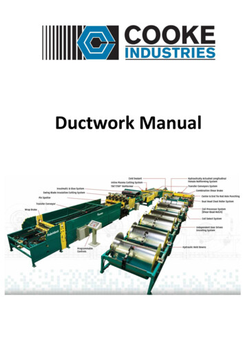
2Plan the Antenna InstallationBefore you begin, consider the following antennainstallation guidelines.Figure 3: Blockage from ObstructionIMPORTANT!Be sure to follow the guidelines below.Damage caused by an improper installation isnot covered under KVH warranty. Minimize blockage. The antenna requires aclear view of the sky to receive satellite TV(see Figure 3). The fewer obstructions, thebetter the system will perform.Make sure the mounting surface is flat, level,wide enough to accommodate the antenna’sbase (see Figure 4), strong enough to supportthe antenna’s weight, and rigid enough toprevent antenna vibration.IMPORTANT!When placed on the mounting surface, all fourmounting plates must lay flat against the roof(within 7/16") to avoid warping the base anddamaging the antenna.20 to 70 Look AngleBlocked!AntennaObstructionABVehicle RoofObstructionHeight (A)Min. Distancefrom Antenna (B)8"19.5"10"26"12"32.5"14"39"16"45.5"Figure 4: Antenna DimensionsFront of Vehicle Select an antenna mounting location on thecenterline of the vehicle with the antenna’scable connector facing the rear of the vehicle.Be sure to mount the antenna near enough tothe TV-Hub inside the vehicle to allow you toconnect the 50 ft. (15 m) coax cable betweenthem, while still maintaining sufficient slackin the cable.FWDVehicleCenterline5 x Ø0.19"13.5"34.3 cmAntennaAntenna(TopView)View)(TopNOTE: If you need to use a longer cable, use a RG-6(75 ) cable that does not exceed 100 ft (30 m). Once you’ve chosen a location for theantenna, identify a safe location nearby forthe 5/8" cable access hole in the roof.1.5"3.8 cmCable ConnectorMountingPlateIMPORTANT!Locate the cable access hole at least 6" awayfrom the connector, making sure you will notdrill into any existing wires or aestheticstructures inside the vehicle.4Antenna(Side View)13.12"33.3 cm
3Plan the TV-Hub InstallationConsider the following TV-Hub installationguidelines. LED LightsSelect a mounting location in a dry, wellventilated area inside the vehicle away fromany heat sources. Do not install the TV-Hub in an areasurrounded by metal or near any electricaldevices that emit RF noise. The TV-Hub can be mounted horizontally orvertically on a flat surface (see Figure 5 andFigure 6). Be sure the TV-Hub LED lights will be visibleto the user. Select a location that will provide adequateclearance for the TV-Hub dimensions (seeFigure 5 and Figure 6). Figure 5: TV-Hub Dimensions - Horizontal Orientation4.36"(11.1 cm)1.73"(4.4 cm)9.34"(23.7 cm)Figure 6: TV-Hub Dimensions - Vertical OrientationLED Lights10.52"(26.7 cm)Leave enough room behind the rear panel(horizontal mount) or below the rear panel(vertical mount) to accommodate connectingthe cables and making service loops withinthe proper bend radius. If you plan to use the TV-Hub’s Wi-Ficonnections, ensure the TV-Hub mountinglocation provides adequate Wi-Fi reception. If you plan to connect the TV-Hub to thevehicle local area network (LAN), choose alocation near an available Ethernet port.NOTE: A template showing the exact locations of theTV-Hub mounting holes and the dimensions betweenthem is provided in the Welcome Kit. Installationdetails are provided in “Mount the TV-Hub” onpage 9.7.90"(20.0 cm)9.34"(23.7 cm)Top View7.90"(20.0 cm)10.94"(27.8 cm)5
4Prepare the Antenna SiteOnce you have identified a suitable antennamounting site according to the guidelinesprovided on page 4, follow these steps to preparethe site and antenna for installation.a. Unfold the antenna mounting template(supplied in the Welcome Kit) and place itonto the mounting surface to use as a guidefor any needed marking. Make sure the“FWD” (forward) arrow is facing front and isparallel to the vehicle’s centerline (seeFigure 7).Figure 7: Mounting TemplateFront of VehicleFWDVehicleCenterlineØ0.19" MountingHole (x20)AntennaAntenna(TopView)View)(TopNOTE: You don’t need to mount the antenna exactlyon the centerline (the closer, the better), but theantenna’s forward arrow must be parallel to it.b. Mark the location for the cable access hole(see requirements on page 4).c. Use a 5/8" hole saw to cut out the cableaccess hole in the vehicle’s roof. Smooth theedges of the hole to protect the cable.Cable ConnectorFigure 8: Attaching the Mounting Platesd. Clean and dry the antenna mounting surface.e. Attach the four supplied metal mountingplates to the bottom of the antenna using theeight M5 screws supplied in the kitpack (seeFigure 8).f.Over each mounting plate, fit a suppliedrubber bumper into the hole in the antenna’sbaseplate (see Figure 8).g. Carefully carry the antenna to the roof of thevehicle.Mounting Plate (x4)M5 Screw (x8)Rubber Bumper (x4)6MountingPlate (x4)
5Wire the AntennaFollow the steps below to wire the antenna.Figure 9: Connecting the Antenna Cablea. Route the RG-6 antenna cable (the end withthe straight connector) down through thecable access hole and into the vehicle. Youmay remove the straight rubber boot foreasier cable routing. Leave an adequateservice loop, approximately 8" (20 cm) ofslack, in the cables for serviceability. Later,you will connect this cable to the TV-Hub.IMPORTANT!Do not kink the cable. Maintain a bend radiusof at least 3" (75 mm).b. Clean and dry the connectors on the RF cableand the underside of the antenna.CAUTIONObserve the safe handling instructions in theMaterial Safety Data Sheet (MSDS) providedwith the silicone grease.c. Fill half of the inner body of the RF cable’sright-angle connector with the suppliedsilicone grease.d. Connect and SLOWLY hand-tighten the RFcable (the end with the right-angle connector)to the antenna, allowing the grease to diffuseand settle into the entire space within theconnector.e. Make sure the RF cable is hand-tightened allthe way into the connector. Then tighten itwith a 7/16" torque wrench set to 20 in-lbs, ora 7/16" wrench for 1/4 turn (see Figure 9).f.Wipe off any excess grease from the outsideof the connector.Figure 10: Mounting the Clamshell Ventilator#6 Screw (x3)ClamshellVentilatorAntennaCableVehicleRoofTo TV-Hubg. Position the rubber boot over the connector tohelp protect it from weather (see Figure 9).h. Seal the cable access hole with a liberalamount of silicone sealant or equivalent.i.Install the supplied clamshell ventilator overthe cable access hole. The clamshell’s openingshould face the rear of the vehicle. Secure inplace with the three #6 screws supplied in thekitpack (see Figure 10). Then seal the screwswith silicone sealant (or equivalent).7
6Mount the AntennaFollow these steps to mount the antenna to theroof.a. Apply appropriate construction adhesive tothe bottom of the antenna’s four mountingplates across all of the holes.b. At the mounting location you chose inSection 2 on page 4, place the antenna on thecenterline of the roof so that the cableconnector faces the rear of the vehicle (seeFigure 11).c. Attach the four antenna mounting plates tothe roof using 20 fasteners appropriate for theroof’s construction (see Figure 11).Figure 11: Mounting the AntennaFront of VehicleFWDVehicleCenterlineØ0.19" MountingHole (x20)AntennaAntenna(TopView)View)(TopIMPORTANT!Due to the variation in RV roof construction,consult with the RV manufacturer todetermine the safest fastening method.d. Seal all fasteners with silicone sealant (orequivalent).8Cable ConnectorMountingPlate (x4)
7Mount the TV-HubFollow these steps to install the TV-Hub insidethe vehicle:a. Tape the mounting template in the locationselected for the TV-Hub. Punch holes at eachof the two keyhole locations and at themounting tab location.Figure 12: TV-Hub Mounting TemplateFront of TV-Hub7.93"(20.1 cm)Keyhole2 x Ø 0.13"(Ø 0.3 cm)b. Remove the template.c. Drill a 1/8" (3 mm) hole at the three holelocations you marked in Step a.d. Install a #8 Phillips thread-forming screwpartway into one of the keyhole holes leavinga small gap for hooking the TV-Hub onto it.Use the thickness (2.5 mm) of the M10 washer(supplied in the kit) as a gauge for the sizegap to leave.4.86"(12.3 cm)3.17"(8.1 cm)e. Repeat step d for the other keyhole.f.Mounting TabØ 0.13"(Ø 0.3 cm)Peel off the backing on the adhesive-backedwasher (supplied in the kit) and place it overthe mounting tab hole (see Figure 12).g. Align the wide part of the TV-Hub’skeyholes, as shown in Figure 13, over thescrews, then slide downwards to secure thescrews into the narrow part of the keyholes.Figure 13: TV-Hub Keyholes and Mounting TabKeyhole (x2)h. Press the rear mounting tab on the TV-Hubonto the adhesive washer and install the third#8 Phillips thread-forming screw in themounting tab hole.Mounting Tab9
8 Wire the Antenna to the TV-HubFollow these steps to connect the antenna to theTV-Hub.Figure 14: TV-Hub Antenna Connectiona. Connect the RF1 cable from the antenna tothe “Antenna” jack on the TV-Hub (seeFigure 14).IMPORTANT!Do not connect anything other than theantenna’s RF1 cable to the “Antenna” jack.The “Antenna” jack has 42 VDC on it whichwill damage other devices such asmultiswitches, DVRs, etc.b. Hand-tighten the RF cable until it is all theway into the “Antenna” jack. Then tighten itwith a 7/16" torque wrench set to 15 in-lbs, ora 7/16" wrench 1/8 turn.10RF1RoofAntennaTo antenna only,supplies 42 VDC
9Wire the ReceiversThe steps for connecting the customer’sreceiver(s) to the TracVision system and settingthem up depends upon the customer’s satelliteTV service (see Figure 15 and Figure 16).Figure 15: TV-Hub A Receiver ConnectionsNOTE: KVH’s TracVision Configuration Wizard,displays a wiring diagram and parts list for all of themost common configurations.TV-Hub AFollow the steps in the applicable section belowto wire the receivers. Then connect the receiver(s)to the customer’s television(s).DIRECTV U.S.Non-SWM ReceiversDIRECTV U.S.SWM ReceiversDISH Network, Bell TV,and Linear ReceiversLinear. . . . . . . . . . . . . . . . . . . . . . . . page 12DIRECTV (SWM) . . . . . . . . . . . . . . page 13DIRECTV (Non-SWM) . . . . . . . . . page 14Figure 16: TV-Hub B Receiver ConnectionsDISH Network/Bell TV . . . . . . . . page 15TV-Hub BLinear Receiver11
9Continued Wire the ReceiversLinear WiringFigure 17: Wiring a Linear ReceiverFollow these steps to connect a linear receiver tothe TracVision system (linear universal single LNBrequired).Connecting a Linear ReceiverConnect an RF cable from the “Receiver” jack onthe TV-Hub to the “Satellite In” jack on thereceiver (see Figure 17).RF1TV-HubReceiverAntennaReceiverSatellite InAC Power12
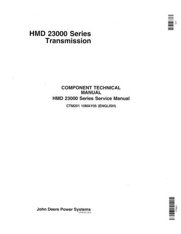
9Continued Wire the ReceiversDIRECTV – SWM WiringFigure 18: Wiring 1 DIRECTV SWM ReceiverFollow these steps to connect DIRECTV SWMreceivers to the TracVision system (circular LNBand TV-Hub A required).NOTE: You can connect non-SWM receivers as well,as explained in “DIRECTV – Non-SWM Wiring” onpage 14.Connecting 1 SWM ReceiverConnect an RF cable from the “SWM” jack on theTV-Hub to the “Satellite In” jack on the receiver/DVR (see Figure 18).RF1TV-HubSWMAntennaSWM ReceiverConnecting 2-8 SWM Receivers (or Tuners)a. Connect an RF cable from the “SWM” jack onthe TV-Hub to the “SWM” input on the SWMsplitter (supplied in the kit) (see Figure 19).b. Connect the SWM splitter’s outputs to the“Satellite In” jack on the receivers/DVRs (or“Network” jack when connecting a Genieclient). You can connect any number of SWMand Genie devices that add up to 8 tuners orfewer. Refer to Figure 19 to determine thetuners consumed by each type of device.c. Terminate any unused outputs on the SWMsplitter with the supplied 75 terminatorsand verify all connections are tight.Satellite InAC PowerFigure 19: Wiring a DIRECTV SWM SplitterTV-HubSWMTerminateunusedoutputsSupports up to 8 tuners:Each SWM receiver 1 tunerEach SWM DVR 2 tunersEach Genie DVR 5 tunersEach Genie client 0 tunersSWM SplitterIMPORTANT!If you need to receive local channels on the119W satellite, and you want the antenna toautomatically switch between the 101W and119W satellites, you need to use the DIRECTVcoax network. See Appendix B on page 30 fordetails.SWM ReceiverSatellite InAC PowerSWM DVRSatellite InAC PowerGenie DVRSatellite InCOMPONENT VIDEO OUTYPbPrDIGITALAUDIO OUTSATELLITE IN 1IR RECEIVEETHERNETLRVIDEO OUT AUDIO OUTPOWER INPUTS-VIDEO OUTSATAHDMIUSBPHONE JACKAC PowerNetwork Genie ClientNote: Although youmay connectNetwork Genie Client additional Genieclients, only 3 can beactive at one timeNetwork Genie Client13
9Continued Wire the ReceiversDIRECTV – Non-SWM WiringFigure 20: Wiring 1 to 2 DIRECTV Non-SWM ReceiversFollow these steps to connect non-SWM receiversto the TracVision system (circular LNB andTV-Hub A required).IMPORTANT!Non-SWM receivers are limited to manualsatellite switching only.RF1TV-HubNOTE: You can connect SWM receivers as well, asexplained in “DIRECTV – SWM Wiring” onpage 13.AntennaLegacy 2Legacy 1Non-SWM ReceiverConnecting 1-2 Receiversa. Connect an RF cable from the “Legacy 1” jackon the TV-Hub to the “Satellite In” jack on thereceiver (see Figure 20).b. When installing two receivers, connect an RFcable from the “Legacy 2” jack on theTV-Hub to the “Satellite In” jack on thesecond receiver.Connecting 3 or More ReceiversTo connect three or more non-SWM receivers,you need an 8-output multiswitch kit (KVH partno. 72-0677), which includes two DC blocksplitters.a. Connect an RF cable from the “Legacy 1” jackon the TV-Hub to the “Antenna” jack on oneof the DC block splitters (see Figure 21).b. Connect the “Primary” jack on the DC blocksplitter to the “18V” jack on the multiswitch,and connect the “Secondary” jack on the DCblock splitter to the “18V/22KHz” jack on themultiswitch.c. Repeat steps a and b with “Legacy 2” and thesecond DC block splitter using the “13V” and“13V/22KHz” jacks on the multiswitch.d. Connect the multiswitch outputs to the“Satellite In” jacks on the non-SWMreceivers.e. Terminate any unused outputs on themultiswitch with 75 terminators and verifyall connections are tight.14Satellite InAC PowerNon-SWM ReceiverSatellite InAC PowerFigure 21: Wiring 3 DIRECTV Non-SWM ReceiversTV-HubLegacy 2Legacy 1AntennaAntennaDC BlockSplitterDC BlockSplitterSecondary PrimarySecondary Primary13V18V13V/22KHz18V/22KHz18V13V18V/ 13V/22KHz 22KHzMultiswitchAC PowerConnect up to 8 non-SWM receiversSatellite InNon-SWM ReceiverAC Power
9Continued Wire the ReceiversDISH Network and Bell TV WiringFigure 22: Wiring 1 DISH/Bell ReceiverFollow these steps to connect DISH Network orBell TV receivers to the TracVision system(circular LNB required).IMPORTANT!Receivers must be DISH Pro-compatible. Lookfor the DISH Pro logo on the box.RF1TV-HubReceiverConnecting 1 ReceiverConnect an RF cable from the “Receiver” jack onthe TV-Hub to the “Satellite In” jack on thereceiver (see Figure 22).Connecting 2 or More Receiversa. Connect an RF cable from the “Receiver” jackon t
DIRECTV* DISH Network* H20 H21 H22 H23 H24 H25 HR21, HR21 Pro HR22 HR23 HR24 HR34 HR44 311 211 211k 211z Bell TV* 6100 6131 6400 1 Inspect Parts and Get Tools IMPORTANT! For information on the recommended receivers for l