Transcription
Quick Start Guide00825-0100-4100, Rev FADecember 2019Rosemount 3051 Pressure Transmitterand Rosemount 3051CF DP Flow Meterswith WirelessHART Protocol
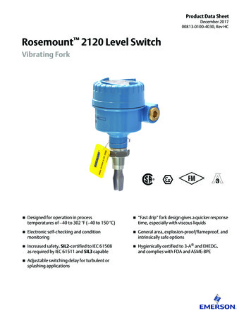
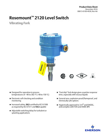
Quick Start GuideDecember 2019Safety MessagesNOTICEThis guide provides basic guidelines for Rosemount 3051 Wireless Transmitters. It does not provideinstructions for configuration, diagnostics, maintenance, service, troubleshooting or Intrinsically Safe(I.S.) installations. Refer to the for more instruction. This manual is also available electronically onEmerson.com/Rosemount.Shipping considerations for wireless products:The unit was shipped to you without the power module installed. Remove the power module prior toshipping the unit.Each power module contains one “D” size primary lithium-thionyl chloride battery. Primary lithiumbatteries are regulated in transportation by the U.S. Department of Transportation, and are alsocovered by IATA (International Air Transport Association), ICAO (International Civil AviationOrganization), and ADR (European Ground Transportation of Dangerous Goods). It is the responsibilityof the shipper to ensure compliance with these or any other local requirements. Consult currentregulations and requirements before shipping.WARNINGExplosions could result in death or serious injury.Installation of this transmitter in an explosive environment must be in accordance with the appropriatelocal, national, and international standards, codes, and practices. Review the approvals section of theRosemount Reference Manual for any restrictions associated with a safe installation.Before connectinga handheld communicator in an explosive atmosphere, ensure that the instruments in the loop areinstalled in accordance with intrinsically safe or non-incendive field wiring practices.Process leaks could result in death or serious injury.To avoid process leaks, only use the O-ring designed to seal with the corresponding flange adapter.Electrical shock could cause death or serious injury.Avoid contact with the leads and terminals. High voltage that may be present on leads can causeelectrical shock.Physical accessUnauthorized personnel may potentially cause significant damage to and/or misconfiguration of endusers’ equipment. This could be intentional or unintentional and needs to be protected against.Physical security is an important part of any security program and fundamental to protecting yoursystem. Restrict physical access by unauthorized personnel to protect end users’ assets. This is true forall systems used within the facility.ContentsWireless considerations.3Transmitter installation. 4Troubleshooting. 18Product certifications. 192Emerson.com/Rosemount
December 20191Wireless considerations1.1Power up sequenceQuick Start GuideThe power module should not be installed on any wireless device until theEmerson Wireless Gateway (Gateway) is installed and functioning properly.This transmitter uses the green power module (order model number701PGNKF). Wireless devices should also be powered up in order ofproximity from the Gateway, beginning with the closest. This will result in asimpler and faster network installation. Enable Active Advertising on theGateway to ensure that new devices join the network faster. For moreinformation, see the Emerson Wireless Gateway Reference Manual.1.2Connecting the transmitter with a Field CommunicatorIn order for the Field Communicator to interface with the transmitter, thepower module must be connected. This transmitter uses the green powermodule (order model number 701PGNKF). Figure 1-1 shows how to connectthe Field Communicator to the transmitter. Open the power modulecompartment to hook up the leads.Figure 1-1: Field Communicator ConnectionsQuick Start Guide3
Quick Start Guide2Transmitter installation2.1Mount the transmitterDecember 2019Figure 2-1: Panel Mount Coplanar Flange5/16 x 1½ panel bolts are customer supplied.Figure 2-2: Pipe Mount Coplanar Flange4Emerson.com/Rosemount
December 2019Quick Start GuideFigure 2-3: Panel Mount Traditional FlangeFigure 2-4: Pipe Mount Traditional FlangeFigure 2-5: Panel Mount Rosemount 3051TQuick Start Guide5
Quick Start GuideDecember 2019Figure 2-6: Pipe Mount Rosemount 3051T6Emerson.com/Rosemount
December 20192.1.1Quick Start GuideMount the transmitter in liquid applicationsProcedure1. Place taps to the side of the line.2. Mount beside or below the taps.3. Mount the transmitter so the drain/vent valves are oriented upward.Figure 2-7: Mounting the Transmitter in Liquid ApplicationsIn-line2.1.2Mount the transmitter in gas applicationsProcedure1. Place taps in the top or side of the line.2. Mount beside or above the taps.Figure 2-8: Mounting the Transmitter in Gas ApplicationsIn-lineQuick Start Guide7
Quick Start Guide2.1.3December 2019Mount the transmitter in steam applicationsProcedure1. Place taps to the side of the line.2. Mount beside or below the taps.3. Fill impulse lines with water.Figure 2-9: Mounting the Transmitter in Steam ApplicationsIn-line2.1.4Bolting considerationIf the transmitter installation requires assembly of the process flanges,manifolds, or flange adapters, follow the assembly guidelines to ensure atight seal for optimal performance characteristics of the transmitters.Use only bolts supplied with the transmitter or sold by Emerson as spareparts. Figure 2-10 illustrates common transmitter assemblies with the boltlength required for proper transmitter assembly.8Emerson.com/Rosemount
December 2019Quick Start GuideFigure 2-10: Common Transmitter AssembliesACD4 2.25-in. (57 mm)4 1.75-in. (44 mm)B4 1.75-in.(44 mm)4 1.50-in.(38 mm)4 1.75-in. (44 mm)4 2.88-in. (73 mm)A.B.C.D.Transmitter with coplanar flangeTransmitter with coplanar flange and optional flange adaptersTransmitter with traditional flange and optional flange adaptersTransmitter with coplanar flange and optional manifold and flangeadaptersBolts are typically carbon steel or stainless steel. Confirm the material byviewing the markings on the head of the bolt and referencing Table 2-1. Ifbolt material is not shown in Table 2-1, contact a local Emersonrepresentative for more information.Carbon steel bolts do not require lubrication, and the stainless steel bolts arecoated with a lubricant to ease installation. However, do not apply additionallubricant when installing either type of bolt.Table 2-1: Torque Values for the Flange and Flange Adapter BoltsBolt materialHead markingsCarbon Steel (CS)Stainless Steel (SST)InitialtorqueFinaltorque300 in-lb650 in-lb150 in-lb300 in-lbB7M316B8M316316RSTM316SW316Use the following bolt installation procedure:Quick Start Guide9
Quick Start GuideDecember 2019Procedure1. Use the fingers to tighten the bolts.2. Torque the bolts to the initial torque value using a crossing pattern.See Table 2-1 for initial torque value.3. Torque the bolts to the final torque value using the same crossingpattern.See Table 2-1 for final torque value.4. Verify the flange bolts are protruding through the sensor modulebolt holes before applying pressure.2.1.5O-rings with flange adaptersWARNINGFailure to install proper flange adapter O-rings may cause process leaks,which can result in death or serious injury. The two flange adapters aredistinguished by unique O-ring grooves. Only use the O-ring that is designedfor its specific flange adapter, as shown below.Figure 2-11: O-ring LocationRosemount 3051S/3051/2051ABCDA.B.C.D.Flange adapterO-ringPFTE-based profile (square)Elastomer profile (round)Whenever the flanges or adapters are removed, visually inspect the O-rings.Replace them if there are any signs of damage, such as nicks or cuts. If youreplace the O-rings, re-torque the flange bolts and alignment screws afterinstallation to compensate for seating of the PTFE O-ring.10Emerson.com/Rosemount
December 20192.1.6Quick Start GuideEnvironmental seal for housingFor NEMA 4X, IP66, and IP68 requirements, use thread sealing (PTFE) tapeor paste on male threads of conduit to provide a water and dust tight seal.Consult factory if other ingress protection ratings are required.For M20 threads, install conduit plugs to full thread engagement or untilmechanical resistance is met.2.1.7Inline gage transmitter orientationThe low side pressure port (atmospheric reference) on the inline gagetransmitter is located in the neck of the transmitter, behind the housing. Thevent path is 360 degrees around the transmitter between the housing andsensor (see Figure 2-12).Keep the vent path free of any obstruction, such as paint, dust, andlubrication, by mounting the transmitter so that the process can drain away.Figure 2-12: Inline Gage Low Side Pressure PortAA. Low side pressure port (atmospheric reference)2.1.8Install high pressure coned and threaded connectionThe transmitter comes with an autoclave connection designed for pressureapplications. Follow the steps below to properly connect the transmitter toyour process.Procedure1. Apply a process-compatible lubricant to the gland nut threads.2. Slip the gland nut onto the tube; then thread the collar onto the tubeend.The collar is reverse threaded.3. Apply a small amount of process-compatible lubricant to the tubecone to help prevent galling and facilitate sealing. Insert the tubinginto the connection and use the fingers to tighten the bolts.4. Tighten the gland nut to a torque of 25 ft-lb.Quick Start Guide11
Quick Start GuideDecember 2019NoteA weep hole has been designed into the transmitter for safety andleak detection. If fluid begins to leak from the weep hole, isolate theprocess pressure, disconnect the transmitter, and reseal until theleak is resolved.2.2Consider housing rotationTo improve field access to wiring or to better view the optional LCD display:Figure 2-13: Housing RotationAA. Housing rotation set screw (5/64-in.)Procedure1. Loosen the housing rotation set screw using a 5/64-in. hex wrench.2. Rotate the housing clockwise to the desired location.3. If the desired location cannot be achieved due to thread limit, rotatethe housing counterclockwise to the desired location (up to 360 from thread limit).4. Retighten the housing rotation set screw to no more than 7 in-lbwhen it reaches the desired location.2.3Connect the power moduleProcedure1. Remove the power module cover.2. Connect the green power module (see Figure 2-14).12Emerson.com/Rosemount
December 2019Quick Start GuideFigure 2-14: Power ModuleAA. Power module2.4Trim the transmitterDevices are calibrated by the factory. Once installed, it is recommended toperform a zero trim on gage and differential pressure transmitters toeliminate error due to mounting position or static pressure effects. A zerotrim can be performed using either a Field Communicator or configurationbuttons.For instructions using AMS Wireless Configurator, see the Rosemount 3051Wireless Reference Manual.NoteWhen performing a zero trim, ensure the equalization valve is open and allwet legs are filled to the correct level.CAUTIONIt is not recommended to zero an absolute transmitter, Rosemount 3051CAor 3051TA models.2.4.1Trimming with a Field CommunicatorProcedure1. Equalize or vent the transmitter and connect Field Communicator.2. At the menu, input the HART Fast Key sequence.3. Follow the commands to perform a zero trim.4. From the Home screen, enter the Fast Key sequence:Device dashboard Fast KeysQuick Start Guide2, 1, 213
Quick Start GuideDecember 2019For connecting with a Field Communicator, refer to Figure 1-1.2.4.2Trimming with digital zero trim buttonProcedure1. Set the transmitter pressure.2. Remove the electronics housing cover.3. Press and hold the Zero button for two seconds to perform a digitalzero trim.4. Reinstall transmitter housing cover. Ensure a proper seal by installingthe electronics housing cover so that polymer contacts polymer (i.e.no O-ring visible).ADoerlZita imig TrFigure 2-15: Digital Zero ButtonA. Digital zero buttonNoteA zero trim can also be completed using AMS Wireless Configuratoronce the device has joined the network.2.5Verify transmitter configurationOperation can be verified in four locations: At the device via the Local Display (LCD display). By using the Field Communicator. Via the Emerson Wireless Gateway’s integrated web interface. Via AMS Wireless Configurator.2.5.1Verify transmitter configuration using LCD displayThe LCD display will show the output values at the same rate as the wirelessupdate rate. Refer to the Rosemount 3051 Wireless Reference Manual for14Emerson.com/Rosemount
December 2019Quick Start Guideerror codes and other LCD display messages. Press and hold the Diagnosticbutton for at least five seconds to display the TAG, Device ID, Network ID,Network Join Status, and Device Status screens.Searching fornetwork2.5.2Joining networkConnected RCHNGNEGOTLIM-OPOKVerify transmitter configuration using Field CommunicatorFor HART Wireless transmitter communication, a Rosemount 3051 Wirelessdevice descriptor is required. For connecting with a Field Communicator,refer to Figure 1-1.From the Home screen, enter the Fast Key sequence:Device dashboard Fast Keys3, 5Table 2-2: Device Revision 1, DD Revision 1 Fast KeysFunctionFast KeysTag2, 1, 1, 1, 1Date2, 1, 1, 1, 5Descriptor2, 1, 1, 1, 3Message2, 1, 1, 1, 4Long Tag2, 1, 1, 1, 2Network ID2, 2, 1, 1Join Device to Network2, 2, 1, 2Update Rate2, 1, 4Range Values2, 1, 1, 5Transfer Function2, 1, 1,6Units2, 1, 1, 2Lower Sensor Trim3, 5, 1, 1, 2Upper Sensor Trim3, 5, 1, 1, 1Quick Start Guide15
Quick Start GuideDecember 2019Table 2-2: Device Revision 1, DD Revision 1 Fast Keys (continued)2.5.3FunctionFast KeysDigital Zero Trim3, 5, 1, 1, 3Rerange by Applied Pressure2, 2, 2, 2, 1Custom Display Configuration2, 1, 5Scaled Variable2, 1, 7, 1Find Device3, 5, 2Simulate Digital Signal3, 6Verify transmitter configuration using Emerson Wireless GatewayIn the Gateway’s integrated web interface, navigate to the Explorer Statuspage. This page will show whether the device has joined the network and if itis communicating properly.NoteIt may take several minutes for the device to join the network. See theEmerson Wireless Gateway Quick Start Guide for more information.Figure 2-16: Gateway Network Settings16Emerson.com/Rosemount
December 20192.5.4Quick Start GuideVerifying configuration using AMS Wireless ConfiguratorWhen the device has joined the network, it will appear in the AMS WirelessConfigurator as shown in Figure 2-17.Figure 2-17: Wireless Configurator Network SetupQuick Start Guide17
Quick Start Guide3December 2019TroubleshootingIf the device has not joined to the network after power up, verify the correctconfiguration of the network ID and join key. Verify that active advertisinghas been enabled on the Emerson Wireless Gateway. The network ID andjoin key in the device must match the network ID and join key of theGateway.The network ID and join key may be obtained from the Gateway on the Setup Network Settings page on the web interface (see Figure 2-16). Thenetwork ID and join key may be changed in the wireless device by using thefollowing Fast Key sequence. See the Rosemount 3051 Wireless ReferenceManual for further troubleshooting.From the Home screen, enter the Fast Key sequence:Device Dashboard Fast Keys183, 5Emerson.com/Rosemount
December 20194Quick Start GuideProduct certificationsRev 1.64.1European Directive InformationA copy of the EU Declaration of Conformity can be found at the end of theQuick Start Guide. The most recent revision of the EU Declaration ofConformity can be found at Emerson.com/Rosemount.4.2Telecommunication ComplianceAll wireless devices require certification to ensure that they adhere toregulations regarding the use of the RF spectrum. Nearly every countryrequires this type of product certification.Emerson is working with governmental agencies around the world to supplyfully compliant products and remove the risk of violating country directivesor laws governing wireless device usage.4.3FCC and ICThis device complies with Part 15 of the FCC Rules. Operation is subject tothe following conditions: This device may not cause harmful interference.This device must accept any interference received, including interferencethat may cause undesired operation. This device must be installed to ensurea minimum antenna separation distance of 20 cm from all persons.4.4Ordinary Location CertificationAs standard, the transmitter has been examined and tested to determinethat the design meets the basic electrical, mechanical, and fire protectionrequirements by a nationally recognized test laboratory (NRTL) as accreditedby the Federal Occupational Safety and Health Administration (OSHA).4.5Installing in North AmericaThe US National Electrical Code (NEC) and the Canadian Electrical Code(CEC) permit the use of Division marked equipment in Zones and Zonemarked equipment in Divisions. The markings must be suitable for the areaclassification, gas, and temperature class. This information is clearly definedin the respective codes.4.5.1USAI5 U.S.A. Intrinsically Safe (IS)Ranges 1-5CertificateQuick Start GuideFM19US0050X19
Quick Start GuideDecember 2019StandardsFM Class 3600:2018, FM Class 3610:2018, FM Class3810:2018, ANSI/ISA 60079-0:2013, ANSI/UL60079-11:2014, NEMA 250:2003, ANSI/IEC 60529:2014,ANSI/UL 61010:2016MarkingsIS CL I, DIV 1, GP A, B, C, D T4; CL 1, Zone 0 AEx ia IIC T4;T4(–40 C Ta 70 C) when installed per Rosemountdrawing 03031-1062; Type 4X/IP66/IP68Special Conditions for Safe Use (X):1. The Rosemount 3051 Wireless Pressure Transmitter shall only beused with the 701PGNKF Rosemount SmartPower Battery Pack.2. The inline pressure sensor may contain more than 10 percentaluminum and is considered a potential risk of ignition by impact orfriction. Care must be taken into account during installation and usedto prevent impact and friction.3. The surface resistivity of the transmitter housing is greater than onegigaohm. To avoid electrostatic charge build-up, it must not berubbed or cleaned with solvents or a dry cloth.4.5.2Range 6CertificateCSA 2526009StandardsFM Class 3600 - 2011, FM Class 3610 - 2010, FM Class3810 - 2005, ANSI/ISA 60079-0 - 2009, ANSI/ISA60079-11 - 2009, UL 61010-1 (3rd edition), UL50E (1stEdition)MarkingsIS CL I, DIV 1, GP A, B, C, D T4; CL 1, Zone 0 AEx ia IIC T4;T4(-40 C Ta 70 C) when installed per Rosemountdrawing 03031-1063; Type 4X/IP66/IP68CanadaI6 Canada Intrinsically SafeCertificate CSA 2526009Standards CAN/CSA C22.2 No. 0-M91, CAN/CSA C22.2 No.94-M91, CSAStd C22.2 No. 142-M1987, CSA Std C22.2 No. 157-92, CSAStd C22.2 No. 60529:05Markings20Intrinsically Safe for Class I, Division 1, Groups A, B, C, D, T4when installed per Rosemount drawing 03031-1063; Type 4X/IP66/IP68Emerson.com/Rosemount
December 20194.5.3Quick Start GuideEuropeI1 ATEX Intrinsic SafetyCertificate Baseefa12ATEX0228XStandardsMarkingsEN 60079-0: 2012, EN 60079-11: 2012Ex II 1 G Ex ia IIC T4 Ga, T4(–40 C Ta 70 C) IP66/IP68Special Conditions for Safe Use (X):1. The plastic enclosure may constitute a potential electrostatic ignitionrisk and must not be rubbed or cleaned with a dry cloth.2. The Model 701PGNKF Power Module may be replaced in a hazardousarea. The power module has a surface resistivity greater than 1 GΩand must be properly installed in the wireless device enclosure. Caremust be taken during transportation to and from the point ofinstallation to prevent electrostatic charge build-up.4.5.4InternationalI7 IECEx Intrinsic SafetyCertificateIECEx BAS 12.0124XStandardsIEC 60079-0: 2011, IEC 60079-11: 2011MarkingsEx ia IIC T4 Ga, T4(–40 C Ta 70 C) IP66/IP68Special Conditions for Safe Use (X):1. The plastic enclosure may constitute a potential electrostatic ignitionrisk and must not be rubbed or cleaned with a dry cloth.2. The Emerson 701PGNKF Power Module may be replaced in ahazardous area. The power module has a surface resistivity greaterthan 1 GΩ and must be properly installed in the wireless deviceenclosure. Care must be taken during transportation to and from thepoint of installation to prevent electrostatic charge build-up.4.5.5BrazilI2 INMETRO Intrinsic SafetyCertificate UL-BR 13.0534XStandards ABNT NBR IEC 60079-0:2008 Errata 1:2011, ABNT NBR IEC60079-11:2009MarkingsQuick Start GuideEx ia IIC T4 IP66 Ga, T4(–40 C Ta 70 C)21
Quick Start GuideDecember 2019Special Condition for Safe Use (X):See certificate for special conditions.4.5.6ChinaI3 China Intrinsic SafetyCertificateGYJ13.1362X, GYJ15.1367X [Flow Meters]StandardsGB3836.1-2010, GB3836.4-2010, GB3836.20-2010MarkingsEx ia IIC T4 Ga, T4(–40 70 C)Special Conditions for Safe Use (X):See certificate for special conditions.4.5.7JapanI4 TIIS Intrinsic SafetyCertificate TC22022X (Rosemount 3051C/L), TC22023X (Rosemount3051T), TC22024X (Rosemount 3051CFx)MarkingsEx ia IIC T4 Ga, T4(–20 60 C)Special Conditions for Safe Use (X):See certificate for special conditions.4.5.8EAC – Belarus, Kazakhstan, RussiaIM Technical Regulation Customs Union (EAC) Intrinsic SafetyCertificateTU RU C-US.AA87.B.00534Markings0Ex ia IIC T4 Ga X; (–40 C Ta 70 C)Special Conditions for Safe Use (X):See certificate for special conditions.4.5.9KoreaIP Korea Intrinsic SafetyCertificate13-KB4BO-0295XMarkingsEx ia IIC T4 (–40 C Ta 70 C)Special Conditions for Safe Use (X):See certificate for special conditions.22Emerson.com/Rosemount
December 2019Quick Start Guide4.5.10 Additional CertificationsSBS American Bureau of Shipping (ABS) Type ApprovalCertificate15-HS1405241-PDAIntended Use Marine & Offshore Applications - Measurement of eithergauge or absolute pressure for liquid, gas and vapor.SBV Bureau Veritas (BV) Type ApprovalCertificate23155Requirements Bureau Veritas Rules for the Classification of Steel ShipsApplicationClass notations: AUT-UMS, AUT-CCS, AUT-PORT and AUTIMS; Pressure transmitter type 3051 cannot be installedon diesel enginesSDN Det Norske Veritas (DNV) Type ApprovalCertificateTAA000004FIntended Use DNV GL Rules for Classification - Ships and offshore unitsApplication:Location eDQuick Start Guide23
Quick Start Guide4.624December 2019Declaration of ConformityEmerson.com/Rosemount
December 2019Quick Start GuideQuick Start Guide25
Quick Start Guide26December 2019Emerson.com/Rosemount
December 2019Quick Start GuideQuick Start Guide27
*00825-0100-4100*Quick Start Guide00825-0100-4100, Rev. FADecember 2019Global HeadquartersEmerson Automation Solutions6021 Innovation Blvd.Shakopee, MN 55379, USANorth America Regional OfficeEmerson Automation Solutions8200 Market Blvd.Chanhassen, MN 55317, USA 1 800 999 9307 or 1 952 906 8888 1 800 999 9307 or 1 952 906 8888 1 952 204 8889 1 952 204 omLatin America Regional OfficeEmerson Automation Solutions1300 Concord Terrace, Suite 400Sunrise, FL 33323, USA 1 954 846 5030 1 954 846 5121RFQ.RMD-RCC@Emerson.comEurope Regional OfficeEmerson Automation Solutions EuropeGmbHNeuhofstrasse 19a P.O. Box 1046CH 6340 BaarSwitzerland 41 (0) 41 768 6111 41 (0) 41 768 6300RFQ.RMD-RCC@Emerson.comAsia Pacific Regional OfficeEmerson Automation Solutions1 Pandan CrescentSingapore 128461 65 6777 8211Middle East and Africa Regional OfficeEmerson Automation SolutionsEmerson FZE P.O. Box 17033Jebel Ali Free Zone - South 2Dubai, United Arab Emirates 65 6777 0947 971 4 8118100Enquiries@AP.Emerson.com 971 4 EmersonAutomation-SolutionsTwitter.com/Rosemount ntMeasurement 2019 Emerson. All rights reserved.Emerson Terms and Conditions of Sale areavailable upon request. The Emerson logo is atrademark and service mark of Emerson ElectricCo. Rosemount is a mark of one of the Emersonfamily of companies. All other marks are theproperty of their respective owners.
2.1.1 Mount the transmitter in liquid applications. Procedure 1. Place taps to the side of the line. 2. Mount beside or below the taps. 3. Mount the transmitter so the drain/vent valves are oriented upward.