Transcription
Martindales's Bevel AnglesPage 1 of 3MARTINDALE'SBEVEL ANGLESBINS-TOWERS-HIP & VALLEY ROOFSBEVEL ANGLESFOR THREE DIMENSIONAL CONNECTIONSTAPERED BIN, HOPPER & TOWER CORNER ANGLESDIAGRAMS FOR QUICK SOLUTIONSFORMULAS FOR SPECIAL CONDITIONSHIP & VALLEY ROOF FRAMING CONNECTIONSSKETCHES TO LOCATE BEVEL ANGLES REQUIREDFORMULAS FOR BEVEL ANGLESANALYTIC PROOF OF DF created with pdfFactory trial version www.pdffactory.com1/20/2007
Martindales's Bevel AnglesPage 2 of 3TABLES OF HIP & VALLEY BEVEL CONNECTION ANGLESBYFRANK L. MARTINDALEREGISTERED PROFESSIONAL ENGINEERCopyright 1948Frank L. MartindalePublished byFrank L. MartindalePhiladelphia, Pa.CONTENTSPrefaceGeneral Notespage 4page 5PART ICORNER ANGLES-TAPERED BINS, HOPPERS & TOWERSUse of Diagramspage 6Typical Bin Sketchpage 7Diagrams and Examplespage 8 to 13Formulaspage 15PART IIHIP & VALLEY FRAMING ANGLESCommentpage 16Use of Sketches, Formulas and Tablespage 17Formulas, H. & V. Framing Anglespage 18Roof Sketch and Location Formulaspage 19Typical Connection Sketchespage 20 to 31Proof of Formulaspage 32 to 37Notes on Tables of H. & V. Framing Anglespage 38Tables of H. & V. Framing Anglespage 40 to 62file://D:\Downloads\Martindale\MARTIN.HTMPDF created with pdfFactory trial version www.pdffactory.com1/20/2007
Martindales's Bevel AnglesPage 3 of 3PREFACEThere is a scarcity of information relating to the solution of three dimensionalangles as required for bevel corner angles for tapered bins, hoppers, chutes,towers, spires, masts and other tapered structures, and for hip and valley roofframing angles, and practically no prepared tables for ready referenceThis book is designed to supply such information and to present the subjectbriefly and concisely and to publish for the first time diagrams and tables ofbeveled angles that will supply a considerable portion of such angles withoutcomputation. Formulas are given for angles not previously included, and newformulas for hip and valley framing angles easier to use.file://D:\Downloads\Martindale\MARTIN.HTMPDF created with pdfFactory trial version www.pdffactory.com1/20/2007
Martindales's Bevel Angles: General NotesPage 1 of 1GENERAL NOTESBevel corner angles for tapered bins, hoppers, chutes, towers and othertapered structures are dealt with in Part I and hip and valley roof framing angles inPart II.PART I provides diagrams and formulas for finding the pitch of the bevelcorner angles for tapered bins, hoppers, chutes, towers, spires, masts and othersimilar structures. The diagrams furnish the bevel corner angle directly from theside slopes for rectangular bins, hoppers, etc. The formulas provide the means offinding the bevel corner angle for any shaped structure.PART II provides sketches of various roof arrangements, sketches of typicalhip and valley roof framing connections, formulas for finding the horizontalposition of the hip or valley, formulas for the hip and valley roof framing angles,tables of hip and valley roof framing angles for various roof slopes and hip orvalley positions and analytic proof of the formulas given.The sketch of various hip and valley roof arrangements indicate the valus ofthe horizontal locating angle for hip and valleys for different combinations of roofslopes and intersecting angles.The sketches of typical hip and valley roof framing connections illustratetypical purlin and rafter connections and locate the several bevel framing anglesused for making such connections, including angles for cuts, clearance, locatingfrom top or bottom of purlin and other required triangulation.The tables of hip and valley framing angles are given for 23 roof slopes, theeven inch pitch roof slopes of vertical and horizontal pitch. For each roof slope thepitches of the twelve framing angles are given at even degree positions of the hipor valley, as indicated by 51 positions of the locating angle D from 20 to 70 . Thepitches are given to the nearest 1/32" of pitch. This arrangement given the pitchesclose enough together so that the pitch for any intermediate position of the hip orvalley can be found by interpolation, for the slopes given.The formulas are given for the bevel framing angles for the solution of theangles for roof slopes not included in the tables.Analytic proof of the formulas are given for students and others interested, asthe formulas are new. These formulas are based upon the roof slope and thehorizontal angles between the ridge and valley, for valley framing angles, andbetween the hip and eave for hip framing angles.-- 5 -[contents] [previous DF created with pdfFactory trial version www.pdffactory.com[next page]1/20/2007
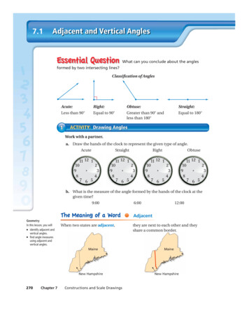
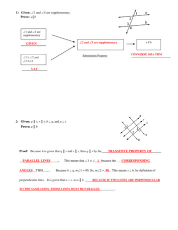
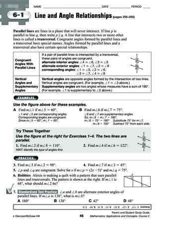
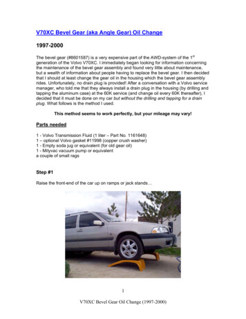
Martindale's BEVEL ANGLES: Part I, page 6Page 1 of 1PART IBeveled Corner AnglesTapered Bins, Hoppers, Chutes, Towers, Spires, Masts, Etc.USE OF DIAGRAMSThere are three diagrams covering the full range of slope combinations forrectangular tapered bins, hoppers, chutes, towers, etc., that is, for corners square inplan or horizontal section. The Typical Bin Sketch shown on the following pageindicates the slope combinations covered by each diagram.For a particular problem select the diagram that includes sides with slopescorresponding to your problem. It is only necessary to find the correct pitch forone side along the side edge of the diagram, and follow the line to the intersectionof the pitch line at the top of the diagram for the other side, and at that point ofintersection, the curves show the pitch of the resulting corner angle. The examplesgiven on the page opposite each diagram outlines the procedure more in detail.All pitch lines are shown at 1/8" intervals. The pitch to the nearest 1/16" ofpitch can be read by interpolation.Note that the diagrams are for corners SQUARE IN PLAN only. To find thebevel of corners where the sloping sides meet in an acute or obtuse angle in plan,see formulas page 15.Note that the bevel of the corner for any two slopes is the same whether theymeet right or left hand to the examples given.Hip corners for tapered towers can be found in the same manner as for bins,as the corners would be the same as an inverted bin with the same slopes.Similarly the beveled corners of any tapered structure such as chutes, masts, spiresand the like can be found by reference to the proper diagram.[contents] [previous page] [next DF created with pdfFactory trial version www.pdffactory.com1/20/2007
Martindale's BEVEL ANGLES: Part I, page 7file://D:\Downloads\Martindale\martinPg7.htmPDF created with pdfFactory trial version www.pdffactory.comPage 1 of 21/20/2007
Martindale's BEVEL ANGLES: Part I, page 7[contents] [previous DF created with pdfFactory trial version www.pdffactory.comPage 2 of 2[next page]1/20/2007
Martindale's BEVEL ANGLES: Part I, page 8Page 1 of 1EXAMPLESforDIAGRAM NO-1BIN PROBLEMGiven a bin corner, square in plan, one side with 6" horizontal pitch slope, theother side with 4" horizontal pitch slope, to find the resulting bevel angle at thevalley.In diagram No. 1, select 6" pitch line on Side A, follow to the intersectionwith 4" pitch line from Side B. This intersection point lies between the 1 5/8" and1 3/4" pitch line for angle C7. By interpolation the pitch to the nearest sixteenth is1 11/16".TOWER PROBLEMGiven a tapered tower, square in plan, both sides having a 2" horizontal pitchslope, to find the pitch of the resulting hip corner beveled angle.In diagram No. 1, on Side A select the 2" pitch line, follow to the intersectionwith the 2" pitch line from Side B. The point of intersection lies between the 1/4"and 3/8" pitch line for angle C7. By interpolation, the pitch to the nearest sixteenthis 5/16".[contents] [previous page] [next DF created with pdfFactory trial version www.pdffactory.com1/20/2007
Martindale's BEVEL ANGLES: Part I, page 9[contents] [previous DF created with pdfFactory trial version www.pdffactory.comPage 1 of 1[next page]1/20/2007
Martindale's BEVEL ANGLES: Part I, page 10Page 1 of 1EXAMPLESforDIAGRAM NO-2BIN PROBLEMGiven a bin corner, square in plan, one side with 6" horizontal pitch slope andthe other side with 10" vertical pitch slope, to find the resulting bevel angle at thevalley.In diagram No. 2, note that Side B is for horizontal pitches and Side C is forvertical pitches. Select 6" line side B and follow to intersection with 10" line fromside C. This intersection point lies near the 4 3/8" pitch line for the desired angleC7.[contents] [previous page] [next PDF created with pdfFactory trial version www.pdffactory.com1/20/2007
Martindale's BEVEL ANGLES: Part I, page 11[contents] [previous PDF created with pdfFactory trial version www.pdffactory.comPage 1 of 1[next page]1/20/2007
Martindale's BEVEL ANGLES: Part I, page 12Page 1 of 1EXAMPLESforDIAGRAM NO-2BIN PROBLEMGiven a bin corner, square in plan, one side with 10" vertical pitch slope andthe other side with 8" vertical pitch slope, to find the resulting bevel angle at thevalley.In diagram No. 3, select the 10" line side C and follow to intersection with 8"line from side D. This intersection point lies near the 10" pitch line for the desiredangle C7.[contents] [previous page] [next PDF created with pdfFactory trial version www.pdffactory.com1/20/2007
Martindale's BEVEL ANGLES: Part I, page 13[contents] [previous PDF created with pdfFactory trial version www.pdffactory.comPage 1 of 1[next page]1/20/2007
Martindale's BEVEL ANGLES: Part I, page 15[contents] [previous PDF created with pdfFactory trial version www.pdffactory.comPage 1 of 1[next page]1/20/2007
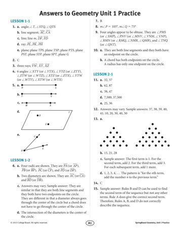
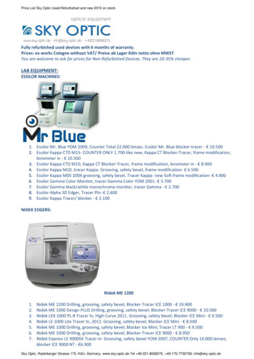
Martindale's BEVEL ANGLES: Part II, page 16Page 1 of 1PART IIHip & Valley Roof Framing AnglesCOMMENTThe following Formulas, Hip and Valley Roof Arrangement Sketch, TypicalConnection Sketches and Tables of Hip and Valley Framing Angles, have beenprepared to assist in solving the bevel angles required for Hip and Valley roofframing as usually framed.The Hip and Valley Roof Arrangement Sketch page 19 is to aid in finding thehorizontal reference angle D used in the formulas and tables.The Typical Connection Sketches pages 20 to 31 incl. are to aid in locatingthe bevel angle marks and the position of the bevel angles.The Formulas page 18 are for solving the bevel angles not covered by thetables.The Tables of Hip and Valley Framing Angles, pages 40 to 62 incl. are forfinding the pitch of the bevel angles directly from the roof slope and horizontalreference angle D of the hip or valley, for the roof slopes included.The Analytic Proof of the formulas, pages 32 to 37 incl. are for reference ofstudents and others interested.[contents] [previous page] [next PDF created with pdfFactory trial version www.pdffactory.com1/20/2007
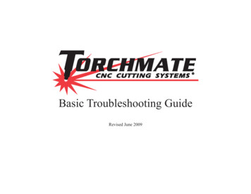
Martindale's BEVEL ANGLES: Part II, page 17Page 1 of 2HIP & VALLEY ROOF FRAMING ANGLESUSE OF SKETCHES, FORMULAS & TABLES OF ANGLESTo use the following sketches, formulas and tables of hip & valley framingangles, the user should be familiar with the arrangement of purlins and hip andvalley rafters assumed as the basis of the formulas. This arrangement is describedbasically under "Notes on Formulas" below.Because the formulas are based upon the roof slope and the horizontal anglebetween the ridge and the valley framing angles, and between the eave and the hipframing angles, the first procedure is to find this hoizontal angle to degrees andminutes. This horizontal angle is marked D and is used in the formulas, sketchesand tablesSketch #1 shows several hip and valley roof arrangements and locates angleD for each arrangement. Formulas for calculating angle D from the two meetingroof slopes and the horizontal angle between the ridges for valleys, and betweenthe eaves for hips, are given for each case.The twelve connection sketches #2 to #13 show six pairs of hip and valleyrafter connections for the same purlin. Note that channel, beam and tee purlins areshown, and that connections with clips above and below the purlin are shown sothat types required for ridge and eave purlin can be selected. Connections withflange clips and bent plates are also shown. Connections using both single andmultiple punching are also shown. The connections are detailed for punched andriveted work. The working points have been projected from one viwe to anotherand to a diagram of the roof, to assist in following the working points from oneface to another. The small triangulation incidental to calculating the drop of hiprafters for clearance, for making cuts and for locating from top or bottom of purlin,are shown and elaborated.The purpose of the connection sketches is to locate and orient the severalbevel angles and to indicate their use for cuts, clearance, etc., as well as the bendand the bevel of the connection. Angle marks for other types of connections can belocated by comparing with somewhat similar types or from the location given withthe formulas.Having located the desired angle marks the pitches can be found in the Tablesof Hip & Valley Framing Angles, provided the roof slope you want is given, andby use of the formulas for other roof slopes.NOTES ON FORMULAS, PAGE 18The formulas for the Hip & Valley Roof Framing Angles are based upon theroof slope and angle D. The twelve bevel angles formulated and given in thetables, cover all the bevel angles formed by two members with web and flangefaces meeting in a three dimensional position from each other, when framed asfollows1. All framing members have web and flange faces square with each other.2. Rafter webs are in a vertical mPDF created with pdfFactory trial version www.pdffactory.com1/20/2007
Martindale's BEVEL ANGLES: Part II, page 17Page 2 of 23. Rafters are parallel to hip or valley.4. Webs of purlins are at right angles to the roof line.5. Purlins are parallel with the ridges.6. The ridge and eave are level.7. Angles A and D are in a level plane.[contents] [previous page] [next PDF created with pdfFactory trial version www.pdffactory.com1/20/2007
Martindale's BEVEL ANGLES: Part II, page 18M A R K S&Page 1 of 1F O R M U L A SHIP & VALLEY ROOF FRAMING CONNECTION ANGLESS & SS Roof SlopesA & A' Horizontal angles between ridges and between eaves.D Horizontal angles between ridge and valley or eaveand hip. Marked D, D', DD & DD' for different roofarrangements shown Sketch #1.B E V E LMARKC O N N E C T I O NLOCATIONA N G L E SFORMULAR1Pitch of Hip or Valley Rafter.tan R1 tan S sin DR2Angle on Hip or Valley Rafter weblocating intersection of Purlin web.tan R2 sin S cos S cos D cotan DR3Angle on Hip or Valley Rafter flg.locating intersection of Purlin web.tan R3 sin S cos S cos D csc R1P1Angle on Purlin web, locating intersection of Hip or Valley Rafter web.tan P1 sin S cotan DP2Angle on Purlin flg. locating intersection of Hip or Valley Rafter web.tan P2 cos S cotan DP3Angle on Purlin web, locating intersection of Hip or Valley Rafter flg.tan P3 cos D sin R1 cos R1 sec SC1Complement of the acute angle betweenPurlin web and Hip or Valley web.tan C1 sin P1 cotan SC2Complement of the acute angle betweenPurlin web and Hip or Valley flange.tan C2 tan R2 cos R3C3Angle between Purlin web and a planeperpendicular to both web and flangeof Hip or Valley Rafter.tan C3 cotan D cos SC4Angle on a plane perpendicular to weband flange of Hip or Valley Rafter,locating intersection of Purlin web.tan C4 sin R1 cotan DC5Angle between Roof plane and Hip orValley Rafter flange.tan C5 sin R1 cotan DC6Angle between Roof plane and Hip orValley Rafter web.tan C6 tan D csc R1Analytic proof of formulas given on pages 32 to 37.[contents] [previous page] [next PDF created with pdfFactory trial version www.pdffactory.com1/20/2007
Martindale's BEVEL ANGLES: Part I, page 19Page 1 of 1- 19 [contents] [previous PDF created with pdfFactory trial version www.pdffactory.com[next page]1/20/2007
PDF created with pdfFactory trial version www.pdffactory.com
PDF created with pdfFactory trial version www.pdffactory.com
PDF created with pdfFactory trial version www.pdffactory.com
PDF created with pdfFactory trial version www.pdffactory.com
PDF created with pdfFactory trial version www.pdffactory.com
PDF created with pdfFactory trial version www.pdffactory.com
PDF created with pdfFactory trial version www.pdffactory.com
PDF created with pdfFactory trial version www.pdffactory.com
PDF created with pdfFactory trial version www.pdffactory.com
PDF created with pdfFactory trial version www.pdffactory.com
PDF created with pdfFactory trial version www.pdffactory.com
PDF created with pdfFactory trial version www.pdffactory.com
PDF created with pdfFactory trial version www.pdffactory.com
PDF created with pdfFactory trial version www.pdffactory.com
PDF created with pdfFactory trial version www.pdffactory.com
PDF created with pdfFactory trial version www.pdffactory.com
PDF created with pdfFactory trial version www.pdffactory.com
PDF created with pdfFactory trial version www.pdffactory.com
Martindale's BEVEL ANGLES: Part II, page 38Page 1 of 1NOTES ONHIP & VALLEY FRAMING ANGLE TABLESWhere the difference in pitch for any angle for one degree of angle D exceeds1/16", the pitch to the nearest 1/16" can be found by interpolating the minutes ofangle D. The greatest difference to be found in the tables is 11/16" and in mostcases much less.For example, given an 8" vertical pitch roof slope and angle D 56 20', tofind pitch of angle P1. On page 47 the pitch for P1 @ 56 is 4-1/2" and for 57 is4-5/16". Subtract 1/16" from the pitch for 56 and we get the correct pitch for 56 20' to be 4-7/16".Note that in some positions the pitch of an angle becomes less as angle Dincreases, and in other positions they increase. The pitch will reduce or increaseaccordingly.Angle C6 is given in degrees and minutes to facilitate adding together thevalues of C6 for each of two sides of a valley corner angle for bins, hoppers, etc.The full inside valley angle C8 for such corners can be found by adding togetherthe angular value of C6 for each of the two sloping sides.[contents] [previous page] [next PDF created with pdfFactory trial version www.pdffactory.com1/20/2007
PDF created with pdfFactory trial version www.pdffactory.com
PDF created with pdfFactory trial version www.pdffactory.com
PDF created with pdfFactory trial version www.pdffactory.com
PDF created with pdfFactory trial version www.pdffactory.com
PDF created with pdfFactory trial version www.pdffactory.com
PDF created with pdfFactory trial version www.pdffactory.com
PDF created with pdfFactory trial version www.pdffactory.com
PDF created with pdfFactory trial version www.pdffactory.com
PDF created with pdfFactory trial version www.pdffactory.com
PDF created with pdfFactory trial version www.pdffactory.com
PDF created with pdfFactory trial version www.pdffactory.com
PDF created with pdfFactory trial version www.pdffactory.com
PDF created with pdfFactory trial version www.pdffactory.com
PDF created with pdfFactory trial version www.pdffactory.com
PDF created with pdfFactory trial version www.pdffactory.com
PDF created with pdfFactory trial version www.pdffactory.com
PDF created with pdfFactory trial version www.pdffactory.com
PDF created with pdfFactory trial version www.pdffactory.com
PDF created with pdfFactory trial version www.pdffactory.com
PDF created with pdfFactory trial version www.pdffactory.com
PDF created with pdfFactory trial version www.pdffactory.com
PDF created with pdfFactory trial version www.pdffactory.com
PDF created with pdfFactory trial version www.pdffactory.com
The Hip and Valley Roof Arrangement Sketch page 19 is to aid in finding the horizontal reference angle D used in the formulas and tables. The Typical Connection Sketches pages 20 to 31 incl. are to aid in locating the bevel angle marks and the position of the bevel angles.