Transcription
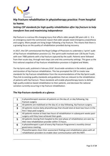
Developments of Hip and Valley Roof Angles based on the Roof LinesOverview of Tetrahedra and Triangles defining a Hip or Valley Roof
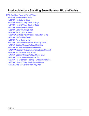
An ALTERNATE MODEL for HIP / VALLEY RAFTERS:Valley orientation:The deck is a level plane,with the plane of the bottomshoulder of the valleydropping away from the deck.DDD90 – DDSSHip run 1cos DDDDihedral angle 90 – A5BmDDDihedral angle 90 – A5Pm2cos DD1 / sin DDPlanDihedral angle 90 – A5PaIsometricProjection:Dihedral angle 90 – A5BaHip orientationR1 is the dihedralangle between thedeck and thebottom face of thehip/valley rafter.R4PaR4PmR4Batan R1R4BmP6mR5BmSSR12cos DD tan R12cos DDR5Pm2tan R5B (cos DD tanR1) / cos DD tanR1 cos DDtan R5P tanR1 / (1 / sin DD) tanR1 sin DDSame R5 angle formulas as the previous analysis.Also: P6 (90 – R5P) – (90 – SS) SS – R5P
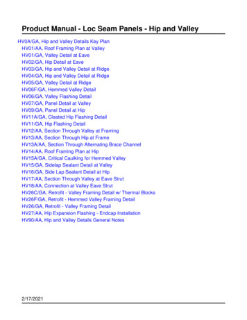
An ALTERNATE MODEL for HIP / VALLEY RAFTERS:Kernels of R4, R5 and A5 AnglesKernels re-scaled to “Hip run” 1: Compare the drawings belowto the models extracted directly from the Valley rafter in theprevious section, as well as the kernels extracted from the stick.R4PR190 - DDDihedral angle 90 – A5P1R5PR4PaR4PmR4BaR4BmR5BmSSR1Dihedral angle 90 – A5BR5PmR5BR4B1R1DD
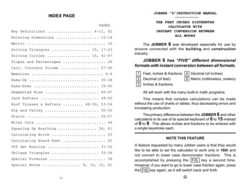
GENERAL HIP / VALLEY MODEL:VALLEY meets RIDGE or HEADERVALLEY meets MAIN COMMON RAFTERVALLEY meets MAIN PURLINDihedral angle between side faceand bottom face of Valley rafter 90 degrees.Dihedral angle between Roofplane and bottom face of Valleyrafter C5.The triangle showing angles labeled Q2and P1 defines the plane of the Main Purlinperpendicular to the Roof plane.Other angular values to expect at theintercept of the Purlin plane and the bottomface of the Hip/Valley: R3, P3, C2, C1, R2Q2Working point for purlin related angles.C5R1R4BP1R5BDDSSAngles toexpect at interceptof Valley Peakmeets Ridge orHeader:DD, R4B, R5B,A5BMAIN SIDE VIEWAnticipated angleswhere Valley Foot meetsMain Common Rafteror Eave:90 – DD, R4P, R5P,A5P, P6For the sake of clarity, only some of the major angles on themodel faces have been labeled. Exploded views will show theremaining angles in more detail.The planes that form the boundaries of the model (planes of R4and R5 angles) are the same planes created by cutting a plane on the topof a post to conform to the bottom face of a Hip/Valley rafter. ExpectR1, A5, R4, and R5 angles at Valley meets Post.
GENERAL HIP / VALLEY MODEL:Kernels extracted from the general modelValley peak meetsMain PurlinValley foot meetsMain CommonRafterMutually perpendicular lines90-R190-R2R4P90-R5PDihedralangle 90-A5P* DihedralQ290-P6angle P290-R390-P3* Note: See alternateC5C5SSdiagram of kernelsextracted from model.Dihedralangle 90-DDP1* DihedralDihedralangle 90-C2angle 90-P2Dihedralangle 90-C1Q2C5R1R4BP1R5BDDSSNote the lines that represent CommonRafter or Purlin Depth : Valley Depth. Theratio cosC5 cosSS / cosR1 cosP1 / cosR2plays a role in determining the location ofangle C5.
GENERAL HIP / VALLEY MODEL:Kernels rotated and re-scaledValley foot meets MainCommon RafterValley peak meets MainPurlin (opposite hand)Dihedral angle 90-DDDihedral angle 90-C190-R21C590-R1Q2R4P90-R3C5190-R5PDihedral angle 90-C2Dihedral angle P2Dihedral angle 90-A5PDihedral angle 90-P2NOTES:Three mutually perpendicular lines form one of the vertices (see “Purlin kernelextracted from Hip kernel”); the kernels may positioned with any face containing aright angle as the “deck”. The angle arrangements shown above match those of thekernels extracted from the stick.The kernels may be split along their respective dihedral angles: Valley peakmeets Main Purlin along 90-C2, 90-C1 or P2, and Valley foot meets MainCommon along 90-A5P, 90-DD or 90-P2. Each split produces an arrangement ofangles as per a standard Hip kernel. The alternate exploded view depicts the kernelssplit along dihedral angles P2 and 90-P2.Angles that upon casual inspection seem to have no direct connection to oneanother are now related through their respective kernels, which may be used fordimensioning as well as simply producing formulas. In addition, since the groups ofangles are now defined, and a given angle occurs in more than one kernel, angularvalues may be determined empirically by developing the kernels using compass andstraightedge only.The sample equations given on the following page cover only a very fewpossible formulas.
VALLEY ANGLE FORMULAS:Valley Peak meetsMain PurlintanR2 tanC5 tanR3tanR3 tanR2 / tanC5KNOWNEQUATION(From “Extracting the Purlinkernel from the Hip kernel”)tanP1 tanSS tanP2Valley Foot meetsMain Common RaftertanR1 tanC5 tan(90-R4P)tanR4P tanC5 / tanR1Divide the kernel along dihedral angleDivide the kernel along dihedral angle90–C2, producing two standard Hip90–A5P, producing two standard Hipkernels. Consider the kernel on the leftkernels. Consider the kernel on the lefthand side:hand side:cosC1 sinC2 / sinR2sinC2 sinR2 cos C1cosC1 sinC5 / sinP1cosDD sinA5P / sinR1sinA5P sinR1 cos DDsinQ2 cosR3 / cosC1cosR2 cosP2 / cosC1cosR5P cos(90-R4P) / cosDDtan(90-R2) tan(90-C2)sin(90-R3)(From Standard Hip kernel)cos(90- Q2) cosR3 / cosC1tanR1 tanSS sinDDtanC2 tanR2 cosR3cosR5P sin R4P / cosDDtan(90-R1) tan(90-A5P) sinR4PtanA5P tanR1 sinR4PConsider the standard Hip kernels created on the right hand side:tan(90-C5) tan(90-C2) sinR3tanC2 tanC5 sinR3tan(90-P2) sin(90-C5) / tanR3tanR3 tanP2 cosC5tanR1 tanSS sinDDtan(90-C5) tan(90-A5P) sin(90-R4P)tanC5 sinR1 / tanDDtanP2 sin(90-C5) / tan(90-R4P)tanA5P tanC5 cosR4PtanR4P tanP2 / cosC5The process may be continued, using any known formula as atemplate (for example, tanP2 cosSS / tanDD), and substitutingcognate angles from the unsolved kernel. Remember tocompensate for trig functions of complementary angles. The nextdiagram depicts an alternate method of extracting Hip kernelsfrom the general model. Rotate any appropriate face to the deck,and apply the methods outlined above to obtain solutions.
GENERAL HIP / VALLEY MODEL:Standard kernels extracted from General Model(kernels re-scaled for clarity)R4PDihedral angle 90-C2P2C5P6C5Dihedral angle 90-A5P90-R3P390-P2Q2Note that the two kernels abovemay be combined along theplane of C5 to create a Dihedral angle 90-C1The two kernels maybe combined along theplane of C5 to createthe kernel examined in“Extracting the Purlinkernel from the Hipkernel”.Dihedral angle 90-DDC590-R1
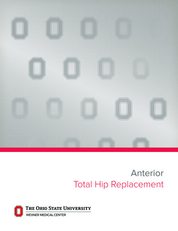
EXTRACTING KERNELS from “the STICK”:Valley Peak meets Main PurlinDD projected to bottom shoulder of Valley is 90-R3Dihedral Angle 90-C190-R3Valley Peak90-R290-R2Q290-R390-C2DDDValley Peak90-DDPlanMain Common RafterMain PurlinFor the purpose of clarity,backing angles and other cuts arenot shown.Valley Foot meetsAdjacent Common Rafter: samekernel as Valley Foot meetsMain Common Rafter,substitute adjacent side values.Also anticipate theseangular values at Valley meetsPost or Eaves.Dihedral Angle 90-DDValley Foot90-R1R4P90-R190-R5PR4P90-A5PValley Foot meets Main Common Rafter90-DD projected to bottom face of Valley is R4Pm(90-D projected is R4Pa at Adjacent Common Rafter)
EXTRACTING KERNELS from “the STICK”:Valley Peak meets HeaderDD projected to bottom plane ofValley is R4BmDihedral Angle DDValley Peak90-R190-R5BmR4Bm90-R1R4Bm90-A5BmHeaderThe same anglesoccur at Valley meetsPost.DDDValley PeakPlanDihedral Angle DValley PeakR4Ba90-R190-R5BaR4Ba90-R190-A5BaValley Peak meets Valley PeakD projected to bottom face of Valley is R4Ba
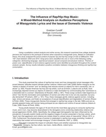
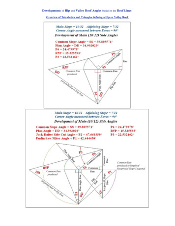
Images of 3D Model . Right Triangles composing the Tetrahedramodeling the Hip Rafter Side Cut Angles at the Peak of the Hip RoofMain Slope 10/12 Adjoining Slope 7/12Corner Angle measured between Eaves in Plan View 90 Development of Tetrahedron modeling the 10/12 Side Angles(Trigonometric Scale)Development of Tetrahedron modeling the 7/12 Side Angles(Trigonometric Scale)
Plan View Lines and Angles
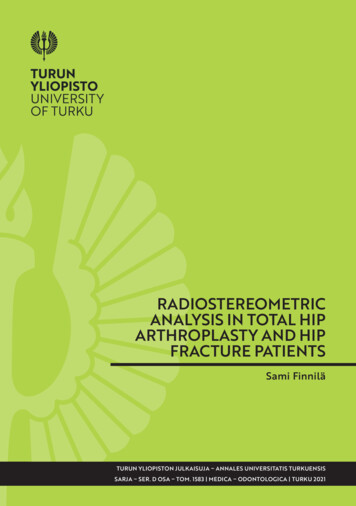
Views of the Tetrahedra modeling the Hip Side Cut Anglesjuxtaposed along the Triangle of the Hip SlopeHip Side Cut Angles at Peak of Hip RafterJuxtaposed Tetrahedra viewed fromTriangles representing upper shoulder of unbacked Hip RafterThe triangles follow the plane of the upper shoulder of an unbacked Hip Rafter. This planepasses through a line perpendicular to the Hip Run, and the slope of the plane, measured fromlevel, is equal to 25.54245 , the Hip Slope Angle. In other words, the Dihedral Angle betweenthe plane containing the Hip Side Cut Angles and the plane following level is the Hip SlopeAngle.
Juxtaposed Hip Side Cut Tetrahedra viewed from 10/12 Side
Juxtaposed Hip Side Cut Tetrahedra viewed from 7/12 SideJuxtaposed Hip Side Cut Tetrahedra viewed from the line of the Rise
Views of the Tetrahedra modeling the Hip Side Cut Anglesseparated along the Triangle of the Hip SlopeOblique View of Hip Side Cut TetrahedraView of Hip Side Cut Tetrahedra from the Triangles of the Hip Slope
Cutting the Backing Angle and comparing 3D Geometry Notes .Images of Right Triangles composing the Tetrahedra extracted from the Hip RoofA Study of the Jack Rafter Side Cut AnglesDevelopments of Tetrahedra extracted from the Hip Roof
Views of the Tetrahedra extracted from the Hip Roofjuxtaposed along the Triangle of the Hip SlopeBird's Eye view of juxtaposed Tetrahedra extracted from the Hip RoofJack Rafter Side Cut Triangles about centerline of Backed Hip Rafter
Oblique view of juxtaposed Tetrahedra extracted from the Hip RoofJack Rafter Side Cut Triangles about centerline of Backed Hip RafterOblique view of juxtaposed Tetrahedra extracted from the Hip Roof showing thehypotenuses of the Hip Side Cut Triangles (unbacked upper shoulder of Hip Rafter)
Comparison of juxtaposed Hip Rafter Side Cut Angle Tetrahedra (left)and juxtaposed Tetrahedra modeling the Jack Rafter Side Cut Angles (right)Juxtaposed Tetrahedra extracted from the Hip RoofView from side of the 10/12 Common Slope Triangle
Juxtaposed Tetrahedra extracted from the Hip RoofView from side of the 7/12 Common Slope Triangle
Juxtaposed Tetrahedra extracted from the Hip RoofView from the line of the RiseViews of the Tetrahedra extracted from the Hip Roof
separated along the Triangle of the Hip SlopeOblique view of 10/12 Roof Surface . Jack Rafter Side Cut AngleOblique view of 7/12 Roof Surface . Jack Rafter Side Cut Angle
Tetrahedra extracted from the Hip Roofviewed from the Triangles of the Hip Slope
Images of Post Type 3D Modelof the Hip Rafter Side Cut AnglesMain Slope 10/12 Adjoining Slope 7/12Corner Angle measured between Eaves in Plan View 90 Development of Post Type Model of the Hip Rafter Side Cut Angles(Trigonometric Scale)
Comparison of all the Model Types . Bird's Eye ViewModels to left and center . Side Cut Angles on upper shoulder of unbacked Hip RafterThe Tetrahedra extracted from the Hip Roof (right) describe a backed Hip RafterComparison of Hip Side Cut Angle Model Types . Bird's Eye ViewPlumb planes passing through the lines on the surface of theTetrahedral Model (left) will produce the Post Type Model (right)Wireframe Sketch illustrating the plumb planes passingthrough the Eave Lines and perpendiculars to the Eave Linessuperimposed on the Tetrahedra extracted from the Hip Roof
Tetrahedral and Post Type Hip Side Cut Angle ModelsView from 10/12 Side of RoofTetrahedral and Post Type Hip Side Cut Angle Models
View from 7/12 Side of RoofEmploying the Post Type 3D Modelof the Hip Rafter Side Cut Anglesto describe the Valley Rafter Side Cut AnglesHip Model upside down . Valley Plan AnglesView of the level plane of the Plan AnglesThe "eaves" now represent the intersecting ridge lines at the Valley roof peak
Hip Model upside down . Valley Side Cut AnglesView of the unbacked shoulder of the Valley RafterThe "eaves" describe the intersecting ridge lines at the Valley roof peak and the"Hip Length" represents the Valley sloping down from the level plane of the Plan AnglesA Review of the Juxtaposed Tetrahedral Models. their Relationship to the Post Type ModelApplication to describe both the Hip and/or Valley Side Cut AnglesLines and Angles seen in Plan View
Wireframe Sketch of Plumb Section Planessuperimposed on the Tetrahedra extracted from the Hip RoofBird's Eye View of the Juxtaposed Tetrahedraillustrating the lines and Side Cut Angles formed by the Plumb Section Planesintersecting the plane of the upper shoulder of an unbacked Hip or Valley Rafter
Unequal Roof Slopes, Non-Rectangular Corner AngleImages of Post Type 3D Model of the Irregular Hip Rafter Side Cut AnglesMain Slope 8.5/12 Adjoining Slope 10/12Corner Angle measured between Eaves in Plan View 120 Development of Post Type Model of Irregular Hip Rafter Side Cut Angles(Trigonometric Scale)
Post Type Model of Irregular Hip Rafter Side Cut AnglesView of the upper shoulder of the Hip Rafter
Post Type Model of Irregular Hip Rafter Side Cut AnglesView from 8.5/12 Side of Roof
Post Type Model of Irregular Hip Rafter Side Cut AnglesView from 10/12 Side of RoofEmploying the Post Type 3D Model
of the Irregular Hip Rafter Side Cut Anglesto describe the Irregular Valley Rafter Side Cut AnglesIrregular Hip Model upside down . Irregular Valley Plan AnglesView of the level plane of the Plan AnglesThe "eaves" now represent the intersecting ridge lines at the Valley roof peakIrregular Hip Model upside down . Irregular Valley Side Cut AnglesView of the unbacked shoulder of the Valley RafterThe "eaves" describe the intersecting ridge lines at the Valley roof peak and the"Hip Length" represents the Valley sloping down from the level plane of the Plan Angles
Overview of the related Hip Side Cut Angleand Jack Rafter Side Cut Angle ModelsTetrahedra extracted from the Hip Roofillustrating the Jack Rafter Side Cut Angles
Tetrahedron relating the Hip Side Cut Angle at the Hip Peak (R4P)the Backing Angle (C5), and the Jack Rafter Side Cut Angle (P2)tan R4P tan P2 cos C5Main Slope 10/12 Adjoining Slope 7/12Corner Angle measured between Eaves in Plan View 90 Comparison of nested Tetrahedra (right)extracted from the Post Type Model (left)
Development of the Tetrahedron extracted from thePost Type Model of the Hip Rafter Side Cut Angles(Trigonometric Scale)
Nested Tetrahedra . Triangles of Common Slope and P6
Nested Tetrahedra . Triangle of Backing Angle
Nested Tetrahedra . Triangle of Hip Side Cut Angle at the Hip Peak
Juxtaposed Tetrahedra relating theHip Side Cut Angle at the Hip Peak (R4P)the Backing Angle (C5), and the Hip Slope Angle (R1)tan R4P tan C5 tan R1Main Slope 10/12 Adjoining Slope 7/12Corner Angle measured between Eaves in Plan View 90 Juxtaposed Tetrahedra extracted from thePost Type Model of the Hip Rafter Side Cut Angles
Development of the juxtaposed Tetrahedra extractedfrom the Post Type Model of the Hip Rafter Side Cut Angles(Angular Scale)
Juxtaposed Tetrahedra . Triangles of Common Slope and P6
Juxtaposed Tetrahedra . Triangles of Backing Angle
Juxtaposed Tetrahedra . Triangle of Hip Side Cut Angle at the Hip Peak
Juxtaposed Tetrahedra and the Triangles of Hip Slope. Plumb Section Plane taken through the line of the Hip Run
Application of Juxtaposed Tetrahedra. Square Beam intersected by Hip RafterMain Slope 12/12 Adjoining Slope 12/12Corner Angle measured between Eaves in Plan View 140 Model of Nonagonal Footprint Pyramid
Developments of the Juxtaposed Tetrahedra
Development of the Beam
Model of Beam . Oblique View
Model of Beam . View from Hip Rafter Foot
Hip Rafter intersects Beam . View of Upper Surfaces (Roof Planes)
Hip Rafter intersects Beam . View of Side Faces
Tetrahedron representing Roof Surface Anglesjuxtaposed with Model of Hip Rafter intersects Beam
Tetrahedra modeling all anglesjuxtaposed with Model of Hip Rafter intersects Beam
An ALTERNATE MODEL for HIP / VALLEY RAFTERS: Isometric Projection: Hip orientation R1 is the dihedral angle between the deck and the bottom face of the hip/valley rafter. DD Plan D 90 - DD R4Bm R4Pm R4Pa R4Ba R1 P6m SS R5Pm R5Bm Dihedral angle 90 - A5Ba tan R5B (cos 2 DD tanR1) / cos DD tanR1 cos DD tan R5P tanR1 / (1 / sin DD .