Transcription
WSO M Mist CollectorMachine MountableInstallation and Operation ManualInstallation, Operation, and Service InformationThis manual is property of the owner. Leave with the unit when set-up and start-up are complete. Donaldson Company reserves the right tochange design and specifications without prior notice.Illustrations are for reference only as actual product may vary.This is the safety alert symbol. It is used to alert you to potential personal injury hazards.Obey all safety messages that follow this symbol to avoid possible injury or death.IOM AK0300401Revision 2
Donaldson Company, Inc.Process owners/operators have important responsibilities relating to combustible hazards.Process owners/operators must determine whether their process creates combustible dust,fume, or mist. If combustible dust, fume, or mist is generated, process owners/operators should at aminimum: Comply with all applicable codes and standards. Among other considerations, current NFPA standardsrequire owners/operators whose processes involve potentially combustible materials to have a currentHazard Analysis, which can serve as the foundation for their process hazard mitigation strategies. Prevent all ignition sources from entering any dust collection equipment. Design, select, and implement fire and explosion mitigation, suppression, and isolation strategies thatare appropriate for the risks associated with their application. Develop and implement maintenance work practices to maintain a safe operating environment, ensuringthat combustible dust, fume, or mist does not accumulate within the plant.Donaldson recommends process owners/operators consult with experts to insure each of theseresponsibilities are met.As a manufacturer and supplier of Industrial Filtration Products, Donaldson can assist process owners/operators in the selection of filtration technologies. However, process owners/operators retain allresponsibility for the suitability of fire and explosion hazard mitigation, suppression, and isolation strategies.Donaldson assumes no responsibility or liability for the suitability of any fire and/or explosion mitigationstrategy, or any items incorporated into a collector as part of an owner/operators hazard mitigation strategy.Improper operation of a dust control system may contribute to conditions in the work area or facility thatcould result in severe personal injury and product or property damage. Check that all collection equipment isproperly selected and sized for the intended use.DO NOT operate this equipment until you have read and understand the instruction warnings in theInstallation and Operations Manual. For a replacement manual, contact Donaldson Torit.This manual contains specific precautionary statements relative to worker safety. Read thoroughly and complyas directed. Discuss the use and application of this equipment with a Donaldson Torit representative. Instruct allpersonnel on safe use and maintenance procedures.Data SheetModel Number Serial NumberShip Date Installation DateCustomer NameAddressFilter TypeAccessoriesOther
WSO Mist Collector, WSO MContentsDescription.1Purpose and Intended Use .1Rating and Specification Information.2Operation.3Inspection on Arrival.4Installation Codes and Procedures.4Installation.4Unit Location.5Site Selection.5Foundations or Support Framing.5Rigging Instructions.5Hoisting Information.5Electrical Wiring.6Standard Equipment.7Provisional Anchor Bolt Recommendations.7Standard Equipment Options.9Flush Mount with Inlet Gasket.9Flanged Inlet Hopper with Legs.9Ceiling Mount Installation.10Collector Stand.11Inlet Hopper with Flex-Duct.12Inlet Hopper with Vibration Isolators.13Inlet Hopper and Impact Separator.14Factory-Installed HEPA or 95% DOP Final Filter.15Final Filter Removal and Installation.15Retrofit Kit Field Installation.15Electrical Connection.15Unwired Units.15Preliminary Start-Up Check.17Maintenance Information.18Operational Checklist.18Filter Removal and Installation.18First Stage Filter Cleaning and Installation.18Primary Filter.19Final Filter.19Troubleshooting.20Service Notes.22DANGER indicates a hazardous situation which, if not avoided, will resultin death or serious injury.WARNING indicates a hazardous situation which, if not avoided, couldresult in death or serious injury.CAUTION, used with the safety alert symbol, indicates a hazardoussituation which, if not avoided, could result in minor or moderate injury.NOTICE is used to address practices not related to personal injury thatmay result in damage to equipment.i
Donaldson Company, Inc.DescriptionDesigned for versatility, the WSO M (Water, Smoke, andOil) mist collector is specifically engineered for watersoluble, smoke, and oil-based mist applications. WSOM mist collector, Machine-Mountable Model collectsairborne mist such as oil, water-soluble, semi-syntheticand synthetic coolant from machining operations. Twostages of filtration, plus an optional HEPA or 95% DOPfilter, provide a cleaner, healthier work environment aswell as a more cost effective means of mist collection.With clean filter airflow capacities of 520 cmh (306cfm) @ 50 Hz and 660 cmh (388 cfm) @ 60 Hz, the WSOM is a strategic component to meeting industrial andgovernment air-quality standards. The high efficiencyfilter cartridges allow air and coolants to be recycled.Designed to increase the versatility of the unit, a varietyof filter media specifically designed for mist collectionis a standard offering on the product line. The primaryfilter is uniquely designed for either water-basedcoolants, straight oils, or thermally-generated smokyapplications. Standard options include drain collectioncontainers, adjustable floor mounting stands, andafterfilters.The WSO M machine-mountable unit is powered by ablower and motor mounted in the filter cabinet.Purpose and Intended Useinjury.Misuse or modification of thisequipment may result in personalDo not misuse or modify.Airborne mist is small droplets of metalworking fluidssuspended in the air. Metalworking fluids includestraight oils, water-soluble coolants, semi-syntheticsynthetic coolants. These fluids perform a variety offunctions such as lubricating or cooling the part or thetool, flushing chips away from the part, and suppressingdust and smoke.Mist is created in two ways: mechanical action orthermal effects. Mechanical action involves coolantused for light lubrication and generally creates mistgreater than one micron in size. Thermal effects occurwhen heat vaporizes the coolant, the vapor cools andrecondenses into a mist. Thermal effects create mistfrom 0.01 to 1 micron in size. Other contaminants, suchas dust from the part or the tool or smoke from thevaporization of the oil or coolant are also generatedwhen using metalworking fluids.The WSO M mist collector is not designed to handlewater mist alone. There should be some type of oilcontent to allow coalescing since water vapor willsimply pass through the filters. The extremes of veryheavy oil and light, thin oil should be avoided. Very heavyoil, similar to tar consistency, will not drain while verylight, thin oil, similar to paint thinner consistency, mayevaporate.Combustible materials such as buffing lint, paper, wood, metal dusts, weld fume, or flammablecoolants or solvents represent potential fire and/or explosion hazards. Use special care whenselecting, installing, and operating all dust, fume, or mist collection equipment when such combustiblematerials may be present in order to protect workers and property from serious injury or damage due to afire and/or explosion.Consult and comply with all National and Local Codes related to fire and/or explosion properties ofcombustible materials when determining the location and operation of all dust, fume, or mist collectionequipment.Standard Donaldson Torit equipment is not equipped with fire extinguishing or explosion protection systems.1
WSO Mist Collector, WSO MRating and Specification InformationAll Units (as per IBC 2009 Specifications):Housing rating, inches water gauge. /- 10Control power.200-Volt, 50/60 Hz220-Volt, 50/60 Hz380-Volt, 50/60 Hz*If unit was supplied with a Record Drawing, thespecifications on the drawing will supersede thestandard specifications above.2
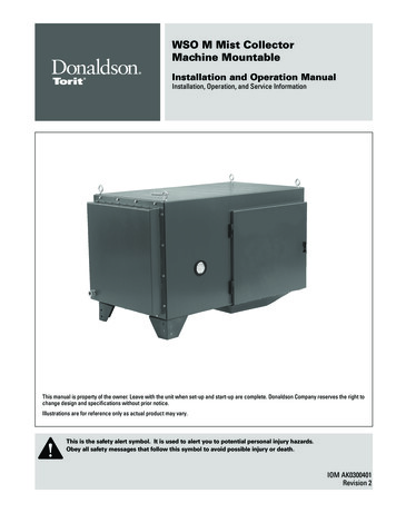
Donaldson Company, Inc.OperationDuring normal operation, contaminated air enters theunit through the dirty-air inlet on the bottom of the unit.The incoming air slows, causing large mist droplets andparticles to fall out of the air stream. The air passesthrough a reusable first-stage filter designed to collectand coalesce large droplets and particles.The primary stage of filtration is the pleated filtercartridge specifically designed to collect, coalesce, anddrain fine mist. As the mist coalesces, the droplets arebig enough to run down the cartridge and drain back intothe collector. The droplets will drain on both the insideand outside of the cartridge. Liquid that collects on theinside of the cartridge drains through the bottom portionof the porous media and into the hopper. Clean, mist-freeair exits the cartridge and discharges through the top ofthe collector.blowerclean-air outletpleated filtercartridgeclean-air plenumlarge dropletsexhaust packfirst-stage filterlarge dropletsblower motordirty-air inlet and collected mist drainUnit Operation3
WSO Mist Collector, WSO MInspection on Arrival1. Inspect unit on delivery.2. Report any damage to the delivery carrier.3. Request a written inspection report from the ClaimsInspector to substantiate any damage claim.4. File claims with the delivery carrier.5. Compare unit received with description of productordered.InstallationUse proper equipment and adoptall safety precautions needed forservicing equipment.Electrical service or maintenance work mustbe performed by a qualified electrician andcomply with all applicable national and localcodes.6. Report incomplete shipments to the delivery carrierand your Donaldson Torit representative.Turn power off and lock out electricalpower sources before performing service ormaintenance work.7. Remove crates and shipping straps. Remove loosecomponents and accessory packages before liftingunit from truck.Do not install in classified hazardousatmospheres without an enclosure rated forthe application.8. Check for hardware that may have loosened duringshipping.9. Use caution removing temporary covers.Installation Codes and ProceduresCodes may regulate recirculatingfiltered air in your facility.Consult with the appropriate authoritieshaving jurisdiction to ensure compliancewith all national and local codes regardingrecirculating filtered air.Safe and efficient operation of the unit depends onproper installation.Authorities with jurisdiction should be consultedbefore installing to verify local codes and installationprocedures. In the absence of such codes, install unitaccording to the National Electric Code, NFPA No.70-latest edition and NFPA 91 (NFPA 654 if combustibledust is present).Turn compressed air supply OFF and bleedlines before performing service or maintenancework.Site selection must account forwind, seismic zone, and otherload conditions when selecting the location forall units.Codes may regulate acceptable locations forinstalling dust collectors. Consult with theappropriate authorities having jurisdiction toensure compliance with all national and localcodes regarding dust collector installation.Collectors must be anchored in a mannerconsistent with local code requirements andanchors must be sufficient to support dead,live, seismic, and other anticipated loads.Consult a qualified engineer for final selectionof anchorage.A qualified installation and service agent must completeinstallation and service of this equipment.All shipping materials, including shipping covers, must beremoved from the unit prior to, or during unit installation.Failure to remove shippingmaterials from the unit willcompromise unit performance.Inspect unit to ensure all hardware is properly installedand tight prior to operating collector.4
Donaldson Company, Inc.Unit LocationRigging InstructionsDonaldson Torit equipment is notdesigned to support site installedducts, interconnecting piping, or electricalservices. All ducts, piping, or electricalservices supplied by others must be adequatelysupported to prevent severe personal injuryand/or property damage.Suggested Tools & EquipmentClevis Pins and ClampsCrane or ForkliftDrift PinsDrill and Drill BitsEnd WrenchesAdjustable WrenchWhen hazardous conditions or materials arepresent, consult with local authorities for theproper location of the collector.Hoisting InformationIf combustible materials willbe processed through thiscollector, local codes may require the collectorbe located either outside or adjacent to anexterior wall to accommodate devices relatedto a fire or explosion mitigation strategy.Consult local codes prior to installation.Site SelectionThis unit can be located on a foundation or structuralframing.Lifting SlingsPipe SealantPipe WrenchesScrewdriversSocket WrenchesSpreader BarFailure to lift the collectorcorrectly can result in severepersonal injury or property damage.Use appropriate lifting equipment and adoptall safety precautions needed for moving andhandling the equipment.A crane or forklift is recommended forunloading, assembly, and installation of thecollector.Location must be clear of all obstructions, suchas utility lines or roof overhang.Provide clearance from heat sources and avoid anyinterference with utilities when selecting the location.Use all lifting points provided.Foundations or Support FramingCheck the Specification Control drawing for weightand dimensions of the unit and components to ensureadequate crane capacity.Prepare the foundation or support framing in theselected location. Foundation or support framing mustcomply with local code requirements and may requireengineering.Foundation and support framing must be capable ofsupporting dead, live, wind, seismic and other applicableloads. Consult a qualified engineer for final selection offoundation or support framing.5Use clevis connectors, not hooks, on lifting slings.Allow only qualified crane operators to lift the equipment.Refer to local codes when using cranes, forklifts, andother lifting equipment.Lift unit and accessories separately and assemble afterunit is in place.Use drift pins to align holes in section flanges duringassembly.
WSO Mist Collector, WSO MCeiling-Mounted Units1. The unit can be suspended or hung from overheadsupports. The supports must be adequate to carrythe live load of the unit and installation performedto reduce sway or vibration to the unit. The dryunit weight is shown on the specification controldrawing shipped with the unit.2. The live load will include the weight of all ancillaryhardware attached to the mist collector, as well asthe weight of the mist-laden, wet filters. Consult thecoolant MSDS for the specific gravity of the coolantto estimate the weight of the mist-laden, wet filters.3. Check the Specification Control drawing for weightand dimensions of the unit, subassemblies, andcomponents to ensure adequate crane capacity.Electrical WiringElectrical installation, service,or maintenance work mustbe performed by a qualified electrician andcomply with all applicable national and localcodes.Turn power off and lock out electricalpower sources before performing service ormaintenance work.Do not install in classified hazardousatmospheres without an enclosure rated forthe application.All electrical wiring and connections, including electricalgrounding, should be made in accordance with the localcodes.Check local ordinances for additional requirements thatapply.The appropriate wiring schematic and electrical ratingmust be used. See unit’s rating plate for required voltage.An electric disconnect switch having adequate ampcapacity shall be installed in accordance with localcodes codes. Check unit’s rating plate for voltage andamperage ratings.Refer to the wiring diagram for the number of wiresrequired for main power wiring and remote wiring.The only component requiring electrical power is theblower motor.6
Donaldson Company, Inc.Standard EquipmentA variety of configuration and mounting options areavailable with the WSO M. The WSO M can be mounteddirectly on the roof of a machining center, suspendedoverhead, or stand-mounted.Provisional Anchor Bolt Recommendations1. Consider Hilti HIT-HY 200 Anchor System orequivalent. Quantity of anchor bolts should match thenumber of holes provided in the base plates.2. Anchor diameter is typically 1/8-in less thanbaseplate hole diameter.3. Corrosive environment or outdoor installation mayrequire stainless steel anchors.Anchor should projecta minimum of 1 3/4-inand account for nut,washer, base plateand shims/grout.General Installation1. Apply a generous amount of sealant when installingattachments.2. Position the collector above the mist-capture zone.See Collector Positioning.3. Do not allow a P-Trap to form when using flexibleduct. See Flex-Duct Positioning.4. On enclosed-machine installations, mount the unitas far from the chip conveyor opening as possible.Installing too close allows the negative pressurecreated by the unit to draw clean shop air, notmist, into the collector. See Enclosed-MachineInstallation.5. On open-machine installations, position the unit’spick-up hood a minimum of 305 mm (12-inches) fromthe mist source. Avoid mounting the pick-up hood tooclose to the mist source of an open machine suchas a wet surface grinder. Installing too close canshorten filter life as the unit will collect large dropletsand particulate instead of mist. See Open MachineInstallation.Embedment depthTypical Foundation AnchormachinecenterCorrectP-trapIncorrectFlex Duct Positioning7machinecenter
WSO Mist Collector, WSO Mmachine centermachine centerIncorrectCorrectCollector Positioninglarge dropletsand particulateenter pick-uphoodCorrect LocationOpen Machine InstallationIncorrect LocationEnclosed Machine Installation8
Donaldson Company, Inc.Standard Equipment OptionsFlush Mount with Inlet GasketFlanged Inlet Hopper with LegsAn inlet gasket is used on machine centers that have alarge, flat unobstructed top surface.This flanged inlet hopper option is for installing acollector on a machine center that has a limited amountof unobstructed top surface.1. Lift the unit into position over the machine center andlower slowly.2. Open the unit’s access door and remove the filtercartridge, filter retention mechanism, and the firststage filter.3. Trace the lower hopper opening onto the machinecenter, remove unit and cut hole.4. Align the bolt template with the cut out and matchdrill the bolt holes using a 5/16-in diameter drill bit.Remove and discard template.5. Remove the protective backing from the gasket andapply to the machine center adhesive side down.6. Lift unit into position and lower slowly. Fasten using6mm bolts, washers, and hex nuts supplied.Start bolts from the inside of the machine center.Do not overtighten. Compress gasket 5 mm (3/16-in)maximum.7. Install a bolt into every rivnut hole.1. Open the units access door and remove the primaryand first stage filters.2. Remove the filter retention system.3. Carefully lift unit into position over the machinecenter and lower into position.4. Trace bolt pattern onto the machine center or matchdrill pattern.5. Cut opening into machine center and drill mountingholes.6. Move the unit aside and apply generous amounts ofsealant to the outside perimeter of the bolt pattern onthe machine center.7. Carefully position unit over the bolt pattern and lowerinto position.8. Install and tighten fasteners into every hole.9. Install filter retention system and filters.legsealanthopperInlet Hopper with Legs9
WSO Mist Collector, WSO MCeiling Mount InstallationFailure to lift the collectorcorrectly can result in severepersonal injury or property damage.Use appropriate lifting equipment and adoptall safety precautions needed for moving andhandling the equipment.A crane or forklift is recommended forunloading, assembly, and installation of thecollector.1. Verify that the ceiling attachment points can bear thelive load.2. Use properly sized cable or chain to attach to eachof the four eyebolts to suspend the unit from theceiling.3. To prevent sway, position the chain or cable to forma 60 degree angle to the top of the unit and a 45degree angle along the sides.Location must be clear of all obstructions,such as utility lines or roof overhang.Ensure weight of oil-laden unit plus weightof required materials and equipment will beadequately supported. Failure to comply mayresult in personal injury and/or property damage.45 customer-suppliedchain or cableeye boltsflat washerexisting mounting holesuse sealantTop View60 Front ViewCeiling Mount10
Donaldson Company, Inc.Collector StandIf collector drainage is notproperly maintained, thecollector may collapse on stand and causesevere personal injury or property damage.Maintain proper collector drainage.Donaldson Torit equipment is not designed tosupport site installed ducts, interconnectingpiping, or electrical services. All ducts, piping,or electrical services supplied by others mustbe adequately supported to prevent severepersonal injury and/or property damage.For applications with limited mounting surfaces, anadjustable stand is available. Bolt the stand’s basesecurely to the floor, attach the collector, and adjustheight from 1676 to 2590 mm (66 to 102-in).1. Install customer-supplied 3/8-16 anchor bolts in thefloor extending 38 mm (1 1/2-in) above surface.2. Level the collector stand and tighten anchor boltssecurely.3. Lift the unit and remove the bolts from the accesspanel located on the bottom of the unit. Remove boltsonly. Do not remove access panel.4. Adjust the stand height by loosening the four lockingbolts on the upper portion of the stand. Slide thissection up to obtain the required height. Tightenbolts securely. Do not adjust the stand over 2590 mm(102-inches).5. Using a crane or forklift, lift the unit into position overthe stand and lower slowly.6. Fasten the top plate of the stand to the unit using thebolts removed in Step 3.7. Tighten all hardware and remove crane.11standextension2590 mm (102-in)maximumhex nutflat washerflat washerlock washerlocking boltbaseCollector Stand
WSO Mist Collector, WSO MInlet Hopper with Flex-DuctThis option is available for ceiling mounted units or unitson customer-supplied stands. Included components area 152 mm (6-in) diameter collar, 3048 mm (10-ft) flexibleduct, two 152 mm (6-in) hose clamps, and a 152 mm (6-in)mounting collar.1. Lift the unit approximately 1524 mm (5-ft).2. Apply sealant around the flex-duct collar toward theoutside of the bolt pattern.3. Align the adapter with the bottom flange of thehopper. Fasten using bolts, washers, and hex nutssupplied.4. Apply sealant around the hopper’s top flange towardthe outside of the bolt pattern.5. Align the top flange of the hopper with the boltpattern on the bottom of the unit and secure using6mm bolts and washers supplied.Note: Install a 6mm bolt into every rivnut.6. Fasten one end of the flexible duct to the collar usinga six inch hose clamp.7. Position the inlet collar on the machine center andtrace the inlet opening and bolt pattern. Remove inletcollar, cut inlet hole, and drill bolt holes using a3/16-in diameter drill bit.8. Apply a 6mm (1/4-in) bead of sealant to the machinecenter, toward the outside edge of the bolt pattern.9. Align collar and fasten to machine center using1/8-in customer-supplied bolts, washers, and hexnuts.sealanthoppersealantflex-duct collarhose clampflex-ducthose clampinlet collarInlet Hopper with Flex-Duct10. Trim the flexible duct to the required length andsecure with remaining hose clamp.Positioning.Do not allow flexible duct tocreate a P-Trap. See Flex-Duct12
Donaldson Company, Inc.Inlet Hopper with Vibration IsolatorsA vibration isolation kit is for top-mounted units installedon machine centers sensitive to vibration. The kitincludes four isolators, a support frame, hopper,152 mm (6-in) diameter flexible duct and a duct collarwith mounting flange and two hose clamps.1. Carefully lift unit and turn over so the bottom inlet isfacing up.2. Remove plugs or existing hardware from the fiveholes on the unit’s left side.3. Apply sealant to the leg’s top flange and secure tounit using the hardware removed in Step 2.4. Apply sealant to the inlet collar toward the outsideedge of the bolt pattern. Fasten inlet collar to thehopper’s bottom flange using the bolts, washers, andhex nuts supplied.11. Apply a 6 mm (1/4-in) diameter bead of sealant to themachine center, toward the outside edge of the boltpattern.12. Align collar and fasten to machine center using1/8-in customer-supplied bolts, washers, and hexnuts.13. Fasten the isolators to the machine center.14. Lift unit into position over the vibration isolators andlower slowly. Fasten using the supplied hardware.15. Connect the flexible duct using the supplied hoseclamps.5. Apply sealant around the hopper’s top flange towardthe outside of the bolt pattern.6. Align the top flange of the hopper with the boltpattern on the bottom of the unit and secure using6mm bolts and washers supplied.7. Attach remaining leg to the right side of the unitfollowing the same procedure.8. Turn unit upright, lift into position over the machinecenter and lower slowly. Do not remove crane.9. Match-drill four holes in the machine center forsecuring the legs.10. Position the inlet collar on the machine center andtrace the inlet opening and bolt pattern. Remove inletcollar, cut inlet hole, and drill bolt holes using a3/16-in diameter drill bit.sealanthoppersealantflex-duct collarhose clampflex-ducthose clampinlet collarInlet Hopper with Vibration Isolators13legvibrationisolator
WSO Mist Collector, WSO MInlet Hopper and Impact SeparatorImpact separators are available for remote-mountedunits in operations generating large amounts of smallparticulate such as surface grinding, polishing, and highspeed cutting.1. Lift the unit approximately 1524 mm (5-ft).2. Apply sealant around the impact separator towardthe outside of the bolt pattern.3. Align the impact separator with the bottom flange ofthe hopper. Fasten using bolts, washers, and hex nutssupplied.sealant4. Apply sealant around the hopper’s top flange towardthe outside of the bolt pattern.sealant5. Align the top flange of the hopper with the boltpattern on the bottom of the unit and secure using6mm bolts and washers supplied.Note: Install a 6mm bolt into every rivnut.hopperimpactseparatorhose clampflexibleduct6. Fasten the flexible duct to the 152 mm (6-in) side inleton the impact separator using a hose clamp.7. Connect opposite end of flexible duct to a customersupplied angular nozzle, inlet collar, or other fitting.8. Install drain collection container by threading thecontainer onto the bottom of the impact separator.The container’s faucet must be closed when the unitis in operation.hoseclampoptional draincollectioncontainerInlet Hopper with Impact Separator14
Donaldson Company, Inc.Factory-Installed HEPA or 95% DOP FinalFilterElectrical ConnectionElectrical installation, service,or maintenance work mustbe performed by a qualified electrician andcomply with all applicable national and localcodes.HEPA filters provide 99.97% efficiency on 0.3 micronparticles. 95% DOP filters are less efficient than HEPA’sbut generally provide longer final filter life.The HEPA or 95% DOP final filter is attached to the sideof the WSO M unit using side-mounted latches.Turn power off and lock out electricalpower sources before performing service ormaintenance work.Final Filter Removal and Installation1. Release the latches on both sides of the HEPA/95%DOP filter frame. Dispose of used filter properly. Donot wash.Retrofit Kit Field InstallationAn afterfilter i
For a replacement manual, contact Donaldson Torit. This manual contains speci c precautionary statements relative to worker safety. Read thoroughly and comply as directed. Discuss the use and application of this equipment with a Donaldson Torit representative. Instruct all personnel on safe use and maintenance procedures. Donaldson Company, Inc.