Transcription
Click here for production status of specific part numbers.MAXM175374.5V to 60V, 3A High-Efficiency, DC-DC Step-DownSiP Power Module with Integrated InductorGeneral DescriptionThe Himalaya series of voltage regulator ICs and powermodules enable cooler, smaller, and simpler power supplysolutions. The MAXM17537 is an easy-to-use, step-downpower module that combines a switching power supplycontroller, dual n-channel MOSFET power switches, fullyshielded inductor, and the compensation components ina low-profile, thermally-efficient system-in-package (SiP).The device operates over a wide input-voltage range of4.5V to 60V and delivers up to 3A continuous output current with excellent line and load regulation over an outputvoltage range of 8V to 24V. The high level of integrationsignificantly reduces design complexity and manufacturing risks, and offers a true plug-and-play power supplysolution, reducing time to market.The device can be operated in the pulse-width modulation(PWM), pulse-frequency modulation (PFM), or discontinuous-conduction mode (DCM) control schemes.The MAXM17537 is available in a low-profile, highlythermal-emissive, compact, 29-pin, 9mm x 15mm x4.32mm SiP package that reduces power dissipation inthe package and enhances efficiency. The package iseasily soldered onto a printed circuit board and suitablefor automated circuit board assembly.Applications Test and Measurement Equipment Distributed Supply RegulationBenefits and Features Reduces Design Complexity, Manufacturing Risks,and Time to Market Integrated Synchronous Step-Down DC-DC Converter Integrated Inductor Integrated FETs Integrated Compensation Components Saves Board Space in Space-ConstrainedApplications Complete Integrated Step-Down Power Supply in aSingle Package Small Profile, 9mm x 15mm x 4.32mm SiP Package Simplified PCB Design with Minimal External BOMComponents Offers Flexibility for Power-Design Optimization Wide Input-Voltage Range from 4.5V to 60V Output-Voltage Adjustable Range from 8V to 24V Adjustable Frequency with External FrequencySynchronization (100kHz to 2.2MHz) PWM, PFM, or DCM Current-Mode Control Programmable Soft-Start Auxiliary Bootstrap LDO for Improved Efficiency Optional Programmable EN/UVLO Operates Reliably in Adverse Industrial Environments Integrated Thermal Protection Hiccup Mode Overload Protection RESET Output-Voltage Monitoring Operating Temperature Range (-40 C to 125 C) FPGA and DSP Point-of-Load Regulator Base-Station Point-of-Load Regulator HVAC and Building Control System19-100592; Rev 0; 7/19Ordering Information appears at end of data sheet.
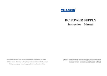
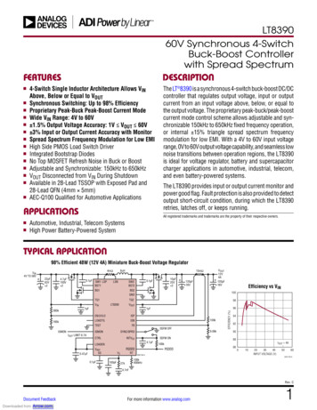
MAXM175374.5V to 60V, 3A High-Efficiency, DC-DC Step-DownSiP Power Module with Integrated InductorTypical Application CircuitVIN15V TO 60VCIN2 x CFBDLBSTLXRESETSSCSS22nFVOUT 12V, 3AOUTCFMODE/SYNCSGNDCOUT3 x 10µFR242.2kΩCF2.2pFRTPGNDR330.1kΩCIN: GRM31CZ72A475KE11COUT: GRM32ER71H106KA12Lwww.maximintegrated.comMaxim Integrated 2
MAXM175374.5V to 60V, 3A High-Efficiency, DC-DC Step-DownSiP Power Module with Integrated InductorAbsolute Maximum RatingsIN to PGND.-0.3V to 65VEN/UVLO, SS to SGND.-0.3V to 65VLX to PGND.-0.3V to (VIN 0.3V)BST to PGND.-0.3V to 70VBST to LX.-0.3V to 6.5VBST to VCC.-0.3V to 65VFB, CF, RESET, MODE/SYNC, RT to SGND.-0.3V to 6.5VDL, VCC to PGND.-0.3V to 6.5VSGND to PGND.-0.3V to 0.3VEXTVCC to PGND.-0.3V to 26VOUT to PGND (VIN 24V).-0.3V to (VIN 0.3V)OUT to PGND (VIN 24V).-0.3V to 24VOutput Short-Circuit Duration.ContinuousOperating Temperature Range . -40 C to 125 CJunction Temperature (Note 1). 150 CStorage Temperature Range. -55 C to 150 CSoldering Temperature (reflow). 240 CStresses beyond those listed under “Absolute Maximum Ratings” may cause permanent damage to the device. These are stress ratings only, and functional operation of the device at theseor any other conditions beyond those indicated in the operational sections of the specifications is not implied. Exposure to absolute maximum rating conditions for extended periods may affectdevice reliability.Package InformationPACKAGE TYPE: 29-PIN SiPPackage CodeL29915#1Outline Number21-100177Land Pattern Number90-100055Thermal Resistance, Four-Layer Board (Note 2):Junction to Ambient (θJA)24 C/WFor the latest package outline information and land patterns (footprints), go to www.maximintegrated.com/packages. Note that a “ ”,“#”, or “-” in the package code indicates RoHS status only. Package drawings may show a different suffix character, but the drawingpertains to the package regardless of RoHS status.Package thermal resistances were obtained using the method described in JEDEC specification JESD51-7, using a four-layer board.For detailed information on package thermal considerations, refer to www.maximintegrated.com/thermal-tutorial.Note 1: Junction temperature greater than 125 C degrades operating lifetimes.Note 2: Package thermal resistance is measured on an evaluation board with natural convection.www.maximintegrated.comMaxim Integrated 3
MAXM175374.5V to 60V, 3A High-Efficiency, DC-DC Step-DownSiP Power Module with Integrated InductorElectrical Characteristics(VIN VEN/UVLO 24V, RRT OPEN (450kHz), VPGND VSGND VMODE/SYNC 0V, LX SS RESET CF DL VCC OUT open, VEXTVCC 0V, VBST to VLX 5V, VFB 1V, TA -40 C to 125 C, unless otherwise noted. Typical values are at TA 25 C.All voltages are referenced to SGND, unless otherwise noted.) (Note 3)PARAMETERSYMBOLCONDITIONSMINTYPMAXUNITSINPUT SUPPLY (VIN)Input-Voltage RangeVIN4.5Input-Shutdown CurrentIIN SHVEN/UVLO 0V, (Shutdown mode)11IQ PFMMODE/SYNC open128Input-Quiescent CurrentIQ DCMDCM mode1.27IQ PWMPWM mode, no load, VOUT VEXTVCC 5V14.560V16μAμA2mAENABLE/UNDERVOLTAGE LOCKOUT (EN/UVLO)EN/UVLO ThresholdEnable Pullup ResistorVENRVEN/UVLO rising1.1851.2151.245VENFVEN/UVLO falling1.061.091.12RENPPullup resistor between IN and EN/UVLOpins3.153.323.456V VIN 60V, IVCC 1mA4.7555.251mA IVCC 45mA4.7555.25VCC 4.3V, VIN 7V5090150mA0.4VVMΩLOW DROPOUT (INLDO)VCC Output-Voltage RangeVCCVCC Current LimitIVCC MAXIN to VCC DropoutVCC DOVIN 4.5V, IVCC 45mAVCC UVRVCC rising4.14.24.3VCC UVFVCC falling3.73.83.9VCC UVLOVVLOW DROPOUT (EXTVCC)EXTVCC OperatingVoltage Range4.84EXTVCC 454.6EXTVCC to VCC DropoutVEXTVCC DOVEXTVCC 5V, IEXTVCC 45mAEXTVCC Current LimitIEXTVCC MAX VCC 4.3V, EXTVCC 8VVV0.6V4585140mA4.755.3μASOFT-START (SS)Charging CurrentISSVSS 0.5VOUTPUT SPECIFICATIONSLine-Regulation AccuracyVIN 15V to 60V, VOUT 12VLoad-Regulation AccuracyTested with IOUT 0 to 3A at VOUT 12VFB-Regulation VoltageVFB REGFB Input-Bias CurrentIFBFB Undervoltage Trip Levelto Cause HiccupHICCUP Timeoutwww.maximintegrated.comVFB HICF0.1mV/V6mV/AMODE/SYNC SGND or MODE VCC0.88750.90.9135MODE/SYNC OPEN0.88750.9150.9360 VFB 1V-750.550.5832768V 75nA0.61VCyclesMaxim Integrated 4
MAXM175374.5V to 60V, 3A High-Efficiency, DC-DC Step-DownSiP Power Module with Integrated InductorElectrical Characteristics (continued)(VIN VEN/UVLO 24V, RRT OPEN (450kHz), VPGND VSGND VMODE/SYNC 0V, LX SS RESET CF DL VCC OUT open, VEXTVCC 0V, VBST to VLX 5V, VFB 1V, TA -40 C to 125 C, unless otherwise noted. Typical values are at TA 25 C.All voltages are referenced to SGND, unless otherwise noted.) (Note 3)PARAMETERSYMBOLCONDITIONSMINTYPMAXUNITSMODE/SYNC PINMODE ThresholdVM DCMMODE/SYNC VCC (DCM Mode)VM PFMMODE/SYNC OPEN (PFM mode)VM PWMMODE/SYNC GND (PWM mode)SYNC Frequency-CaptureRangefSW set by RRTSYNC Pulse WidthSYNC ThresholdVCC 0.6VVCC / 20.61.1 xfSW1.4 xfSW50VIHkHzns2.0VIL0.8VCURRENT LIMITAverage Current-LimitThresholdIAVG LIMIT4.4ART PINSwitching FrequencyAccuracySwitching FrequencyfSWfSW 100kHz to 2.2MHz-12RRT open420Switching FrequencyAdjustable RangeMinimum On-TimeRESET PIN450100tON(MIN)114RESET Output-Level LowIRESET 10mARESET Output-LeakageCurrentVRESET 5.5V-10012%480kHz2200kHz160ns400mV100nAVOUT Threshold forRESET AssertionVOUT OKFVFB falling90.492.594.6%VOUT Threshold forRESET DeassertionVOUT OKRVFB rising93.495.597.7%RESET Deassertion Delayafter FB Reaches 95%Regulation1024Cycles165 C10 CTHERMAL SHUTDOWNThermal-Shutdown ThresholdThermal-Shutdown HysteresisTemperature RisingNote 3: Electrical specifications are production tested at TA 25 C. Specifications over the entire operating temperature range areguaranteed by design and characterization.www.maximintegrated.comMaxim Integrated 5
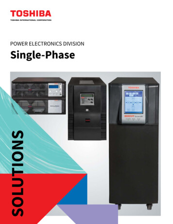
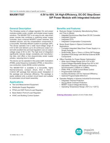
MAXM175374.5V to 60V, 3A High-Efficiency, DC-DC Step-DownSiP Power Module with Integrated InductorTypical Operating Characteristics(VIN VEN/UVLO 24V, VSGND VPGND 0V, TA -40 C to 125 C, unless otherwise noted. Typical values are at TA 25 C. Allvoltages are referenced to GND, unless otherwise noted. The circuit values for different output-voltage applications are as in Table 1,unless otherwise noted.)EFFICIENCY vs. LOAD CURRENT(12V OUTPUT, PFM MODE, fSW 600kHz)EFFICIENCY vs. LOAD CURRENT(12V OUTPUT, PWM MODE, fSW 600kHz)toc0170EFFICIENCY (%)EFFICIENCY (%)VIN 36V96VIN 60VVIN 48V60VIN 36V50VIN 24V40308810828010002000VIN 48V3000toc04VIN 24V40VIN 19V308810840822000300010100VIN 33V90888410822000LOAD CURRENT (mA)www.maximintegrated.comVIN 33V92863000801000toc0910080VIN 48V9420100010100LOAD CURRENT (mA)EFFICIENCY vs. LOAD CURRENT(15V OUTPUT, DCM MODE, fSW 700kHz)EFFICIENCY (%)EFFICIENCY (%)EFFICIENCY (%)VIN 48V01909630001000toc089850VIN 48V4020VIN 60V100VIN 60V4050EFFICIENCY vs. LOAD CURRENT(24V OUTPUT, PFM MODE, fSW 1MHz)toc0760VIN 36VLOAD CURRENT (mA)9070VIN 60V6010EFFICIENCY vs. LOAD CURRENT(24V OUTPUT, PWM MODE, fSW 1MHz)80VIN 24V7030VIN 48VLOAD CURRENT (mA)100VIN 19V8090861000VIN 24V921001000LOAD CURRENT (mA)toc069094200VIN 36VVIN 19V10100EFFICIENCY (%)EFFICIENCY (%)EFFICIENCY (%)501EFFICIENCY vs. LOAD CURRENT(15V OUTPUT, DCM MODE, fSW 700kHz)toc0596VIN 36VVIN 48V4001001000LOAD CURRENT (mA)9860VIN 60V5020100VIN 60VVIN 48V60EFFICIENCY vs. LOAD CURRENT(15V OUTPUT, PFM MODE, fSW 700kHz)9070VIN 36V1010EFFICIENCY vs. LOAD CURRENT(15V OUTPUT, PWM MODE, fSW 700kHz)80VIN 24V7030VIN 60VLOAD CURRENT (mA)1008090840VIN 24V9220VIN 15V909486VIN 15Vtoc03100VIN 15V98800toc0210090EFFICIENCY (%)100EFFICIENCY vs. LOAD CURRENT(12V OUTPUT, DCM MODE, fSW 600kHz)VIN 60VVIN 48V7060VIN 33V50VIN 60V403020100101001000LOAD CURRENT (mA)110100LOAD CURRENT (mA)1000Maxim Integrated 6
MAXM175374.5V to 60V, 3A High-Efficiency, DC-DC Step-DownSiP Power Module with Integrated InductorTypical Operating Characteristics (continued)(VIN VEN/UVLO 24V, VSGND VPGND 0V, TA -40 C to 125 C, unless otherwise noted. Typical values are at TA 25 C. Allvoltages are referenced to GND, unless otherwise noted. The circuit values for different output-voltage applications are as in Table 1,unless otherwise noted.)10mV/div(ACCOUPLED)VOUTSTEADY-STATE SWITCHING WAVEFORMS(VIN 24V, VOUT 12V, IOUT 25mAPFM MODE, MODE OPEN)toc12STEADY-STATE SWITCHING WAVEFORMS(VIN 24V, VOUT 12V, IOUT 3APWM MODE, MODE SGND)toc11STEADY-STATE SWITCHING WAVEFORMS(VIN 24V, VOUT 12V, IOUT 0APWM MODE, MODE s/div1µs/divSTEADY-STATE SWITCHING WAVEFORMS(VIN 24V, VOUT 12V, IOUT 25mADCM MODE, MODE VCC)toc13OUTPUT VOLTAGE vs. LOAD CURRENT(12V OUTPUT, PWM MODE, fSW 600kHz)toc1412.20VIN 48V12.512.14VIN 36V12.12VIN 48V12.1012.0812.06VIN 24VVIN 15VVIN 24VVIN 60VOUTPUT VOLTAGE (V)12.16OUTPUT VOLTAGE )VOUTOUTPUT VOLTAGE vs. LOAD CURRENT(12V OUTPUT, PFM MODE, fSW 600kHz)12.412.3VIN 60VVIN 36V12.2VIN 15V12.112.0212.001µs/divtoc16VIN 36VVIN 48V15.1215.10VIN 19V15.08VIN 24V15.0615.0415.415.010010LOAD CURRENT (mA)www.maximintegrated.com1000VIN 48VVIN 19V15.215.11VIN 36V15.315.00toc1824.1015.515.02100024.15VIN 60V15.615.1410100LOAD CURRENT (mA)24.20VIN 24V15.71OUTPUT VOLTAGE vs. LOAD CURRENT(24V OUTPUT, PWM MODE, fSW 1MHz)toc1715.8VIN 60VOUTPUT VOLTAGE (V)OUTPUT VOLTAGE (V)15.161000OUTPUT VOLTAGE (V)15.1810100LOAD CURRENT (mA)OUTPUT VOLTAGE vs. LOAD CURRENT(15V OUTPUT, PFM MODE, fSW 700kHz)OUTPUT VOLTAGE vs. LOAD CURRENT(15V OUTPUT, PWM MODE, fSW 700kHz)15.2012.0124.05VIN 33V24.00VIN 48VVIN 60V23.9523.9023.8523.80110100LOAD CURRENT (mA)1000110100LOAD CURRENT (mA)1000Maxim Integrated 7
MAXM175374.5V to 60V, 3A High-Efficiency, DC-DC Step-DownSiP Power Module with Integrated InductorTypical Operating Characteristics (continued)(VIN VEN/UVLO 24V, VSGND VPGND 0V, TA -40 C to 125 C, unless otherwise noted. Typical values are at TA 25 C. Allvoltages are referenced to GND, unless otherwise noted. The circuit values for different output-voltage applications are as in Table 1,unless otherwise noted.)toc1924.8POWER-UP AND DOWN THROUGH EN/UVLO(VIN 24V, VOUT 12V, IOUT 25mAPFM MODE, MODE OPEN)toc21POWER-UP AND DOWN THROUGH EN/UVLO(VIN 24V, VOUT 12V, IOUT 3APWM MODE, MODE SGND) toc20OUTPUT VOLTAGE vs. LOAD CURRENT(24V OUTPUT, PFM MODE, fSW 1MHz)24.7VEN/UVLOOUTPUT VOLTAGE (V)24.65V/divVEN/UVLO5V/div24.524.4VIN 48V24.324.1VIN 10V/divVRESET5V/divVRESETVIN 60V24.2110100LOAD CURRENT (mA)POWER-UP WITH 5V BIAS(VIN 24V, VOUT 12V, IOUT 0APWM MODE, MODE SGND)1000LOAD TRANSIENT(VIN 24V, VOUT 12V, IOUT 0A TO 1.5APWM MODE, MODE SGND)toc23toc225V/div4ms/div4ms/divLOAD TRANSIENT(VIN 24V, VOUT 12V, IOUT 1.5A TO 3APWM MODE, MODE vLOAD TRANSIENT(VIN 24V, VOUT 15V, IOUT 0A TO 1.5APWM MODE, MODE SGND)toc25LOAD TRANSIENT(VIN 24V, VOUT 15V, IOUT 1.5A TO 3APWM MODE, MODE SGND)toc26LOAD TRANSIENT(VIN 48V, VOUT 24V, IOUT 0A TO 1.5APWM MODE, MODE A/div400µs/divMaxim Integrated 8
MAXM175374.5V to 60V, 3A High-Efficiency, DC-DC Step-DownSiP Power Module with Integrated InductorTypical Operating Characteristics (continued)(VIN VEN/UVLO 24V, VSGND VPGND 0V, TA -40 C to 125 C, unless otherwise noted. Typical values are at TA 25 C. Allvoltages are referenced to GND, unless otherwise noted. The circuit values for different output-voltage applications are as in Table 1,unless otherwise noted.)LOAD TRANSIENT(VIN 48V, VOUT 24V, IOUT 1.5A TO 3APWM MODE, MODE SGND)toc28VOUTIOUTLOAD TRANSIENT(VIN 24V, VOUT 12V, IOUT 25mA TO 1.5ADCM MODE, MODE VCC)toc29200mV/div(ACCOUPLED)VOUT1A/divIOUTOUTPUT SHORT IN STEADY-STATE(VIN 24V, VOUT 12V, OUTPUT SHORTPWM MODE, MODE SGND)toc31LOAD TRANSIENT(VIN 24V, VOUT 12V, IOUT 25mA TO 1.5APFM MODE, MODE OUTVLX20V/divIOUT5A/div20ms/div1ms/divSTARTUP INTO SHORT(VIN 24V, VOUT 12V, OUTPUT SHORTPWM MODE, MODE SGND)toc32SYNC FREQUENCY AT 840KHZ(VIN 24V, VOUT 12V, IOUT 3APWM MODE, MODE LED)4µs/divMaxim Integrated 9
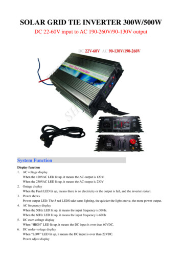
MAXM175374.5V to 60V, 3A High-Efficiency, DC-DC Step-DownSiP Power Module with Integrated InductorTypical Operating Characteristics (continued)(VIN VEN/UVLO 24V, VSGND VPGND 0V, TA -40 C to 125 C, unless otherwise noted. Typical values are at TA 25 C. Allvoltages are referenced to GND, unless otherwise noted. The circuit values for different output-voltage applications are as in Table 1,unless otherwise noted.)BODE PLOT(VIN 24V, VOUT 12V, IOUT 3A)80PHASE103104FREQUENCY (Hz)BODE PLOT(VIN 48V, VOUT 24V, IOUT 3A)120404020-20-40-4020GAIN0-20fCR 38.3kHz,PHASE MARGIN 61.8 103104FREQUENCY (Hz)105-40toc374.01201003.5VIN 24V, VOUT 12V6040402020GAIN00OUTPUT CURRENT (A)8060-4060OUTPUT CURRENTvs. AMBIENT 0GAIN (dB)0fCR 33.8kHz,PHASE MARGIN 60.8 toc3580PHASE( )20GAIN0GAIN (dB)1004020-40806040-20120PHASE( )GAIN (dB)60100PHASE( )toc34100BODE PLOT(VIN 24V, VOUT 15V, IOUT 3A)3.02.5VIN 24V, VOUT 12VVIN 48V, VOUT 12V2.0VIN 48V, VOUT 15V1.5-20fCR 40.0kHz,PHASE MARGIN 64.0 103www.maximintegrated.com104FREQUENCY (Hz)105-40VIN 48V, VOUT 24V1.0020406080100120AMBIENT TEMPERATURE ( C)Maxim Integrated 10
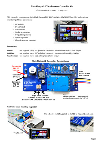
MAXM175374.5V to 60V, 3A High-Efficiency, DC-DC Step-DownSiP Power Module with Integrated InductorPin ConfigurationMODE/SYNCINPGNDDLOUT2625OUT N SiP9mm x 15mm x 4.32mmwww.maximintegrated.comMaxim Integrated 11
MAXM175374.5V to 60V, 3A High-Efficiency, DC-DC Step-DownSiP Power Module with Integrated InductorPin DescriptionPINNAMEFUNCTION1VCC5V LDO Output. The VCC is bypassed to PGND internally through a 2.2µF capacitor. Do not connect anyexternal components to the VCC pin.2RESETOpen-Drain RESET Output. The RESET output is driven low if FB drops below 92.5% of its set value.RESET goes high 1024 clock cycles after FB rises above 95.5% of its set value. See the RESET Outputsection for more details.3RT4SGND5CFCompensation Pin. Connect a 2.2pF capacitor from CF to FB.6FBFeedback Input. Connect FB to the center tap of an external resistor-divider from the OUT to SGND toset the output voltage.7SSSoft-Start Input. Connect a capacitor from SS to SGND to set the soft-start time.8EN/UVLO9, 28IN10, 14-21,27PGND11EXTVCCExternal Power Supply Input for the Internal LDO. Applying a voltage between 4.7V and 24V at theEXTVCC pin bypasses the internal LDO and improves efficiency.12BSTBoost Flying Capacitor Node. Internally a 0.1μF is connected from BST to LX. Do not connect anyexternal components to the BST pin.13LX22-25OUT26DLSwitching Frequency Programming Pin. Connect a resistor from RT to SGND to set the regulator'sswitching frequency. Leave RT open for the default 450kHz frequency. See the Setting the SwitchingFrequency (RT) section for more details.Analog Ground.Enable/Undervoltage-Lockout Input. Connect a resistor from EN/UVLO to SGND to set the UVLOthreshold. By default, the module is enabled with the EN/UVLO pin open.Power-Supply Input. Decouple to PGND with a capacitor; place the capacitor close to the IN and PGNDpins.Power Ground.Switching Node. Leave unconnected; do not connect any external components to the LX pin.Regulator Output Pin. Connect a capacitor from OUT to PGND.Gate Drive for Low-Side MOSFET. Do not connect any external components to the DL pin.29MODE/SYNCPWM/PFM/DCM Mode-Selection Input. MODE pin configures the module to operate in PWM, PFM, orDCM modes of operation. Leave MODE unconnected for PFM operation (pulse skipping at light loads).Connect MODE to SGND for constant frequency PWM operation at all loads. Connect MODE to VCC forDCM operation. The device can be synchronized to an external clock using this pin. See the Mode Selection (MODE) and External Frequency Synchronization sections for more details.EP1, EP2,EP3—Exposed Pad. Create a large copper plane below the module connecting EP1, EP2, and EP3 to improveheat dissipation capability. PGND and SGND are shorted through this plane.www.maximintegrated.comMaxim Integrated 12
MAXM175374.5V to 60V, 3A High-Efficiency, DC-DC Step-DownSiP Power Module with Integrated InductorFunctional NT DESELECTIONLOGICERROR AMPLIFIER/LOOP /SYNCRESETLOGICMaxim Integrated 13
MAXM175374.5V to 60V, 3A High-Efficiency, DC-DC Step-DownSiP Power Module with Integrated InductorDetailed DescriptionThe MAXM17537 is a high-efficiency, high-voltage,synchronous step-down module with dual-integratedMOSFETs that operates over a 4.5V to 60V input, andsupports a programmable output voltage from 8V to 24V,delivering up to 3A current. Built-in compensation for theentire output-voltage range eliminates the need for external components. The feedback (FB) regulation accuracyover -40 C to 125 C is 1.5%.The device features a peak-current-mode control architecture. An internal transconductance-error amplifier produces an integrated error voltage at an internal node thatsets the duty cycle using a PWM comparator, a high-sidecurrent-sense amplifier, and a slope-compensation generator. At each rising edge of the clock, the high-sideMOSFET turns on and remains on until either the appropriate or maximum duty cycle is reached, or the peakcurrent limit is detected. During the high-side MOSFET’son-time, the inductor current ramps up. During the secondhalf of the switching cycle, the high-side MOSFET turnsoff and the low-side MOSFET turns on. The inductorreleases the stored energy as its current ramps downand provides current to the output. The device features aMODE/SYNC pin that can be used to operate the devicein PWM, PFM, or DCM control schemes and to synchronize the switching frequency to an external clock. Thedevice integrates adjustable-input undervoltage lockout,adjustable soft-start, open-drain RESET, auxiliary bootstrap LDO, and DL-to-OUT short-detection features.Mode Selection (MODE)The logic state of the MODE/SYNC pin is latched whenVCC and EN/UVLO voltages exceed the respective UVLOrising thresholds and all internal voltages are ready toallow LX switching. If the MODE/SYNC pin is open atpower-up, the device operates in PFM mode at lightloads. If the MODE/SYNC pin is grounded at power-up,the device operates in constant-frequency PWM modeat all loads. Finally, if the MODE/SYNC pin is connectedto VCC at power-up, the device operates in constant frequency DCM mode at light loads. State changes on theMODE/SYNC pin are ignored during normal operation.PWM Mode OperationIn PWM mode, the inductor current is allowed to go negative. PWM operation provides constant frequency operation at all loads, and is useful in applications sensitiveto changes in switching frequency. However, the PWMmode of operation gives lower efficiency at light loadscompared to PFM and DCM modes of operation.www.maximintegrated.comPFM Mode OperationThe PFM mode of operation disables negative inductorcurrent and additionally skips pulses at light loads for highefficiency. In PFM mode, the inductor current is forced toa fixed peak of 2A (typ) every clock cycle until the outputrises to 102.3% of the nominal voltage. Once the outputreaches 102.3% of the nominal voltage, both the highside and low-side FETs are turned off and the deviceenters hibernation mode until the load discharges theoutput to 101.1% of the nominal voltage. Most of the internal blocks are turned off in hibernation mode to minimizequiescent current. After the output falls below 101.1% ofthe nominal voltage, the device comes out of hibernationmode, turns on all internal blocks, and again commencesthe process of delivering pulses of energy to the outputuntil it reaches 102.3% of the nominal output voltage. Theadvantage of the PFM mode is higher efficiency at lightloads because of lower quiescent current drawn from thesupply. The disadvantage is that the output-voltage rippleis higher compared to PWM or DCM modes of operationand switching frequency is not constant at light loads.DCM Mode OperationDCM mode of operation features constant frequencyoperation down to lighter loads than PFM mode by notskipping pulses, but only disabling negative inductor current at light loads. DCM operation offers efficiency performance that lies between PWM and PFM modesLinear RegulatorThe MAXM17537 has two internal low-dropout (LDO)regulators that power VCC. During power-up, whenthe EN/UVLO pin voltage is above the true shutdownvoltage (0.8V), then the VCC is powered from INLDO.When VCC voltage is above the VCC UVLO thresholdand EXTVCC voltage is greater than 4.7V (typ), theVCC is powered from EXTVCC LDO. Only one of the twoLDOs is in operation at a time depending on the voltagelevel present at EXTVCC. Powering VCC from EXTVCCincreases efficiency at higher input voltages. EXTVCCvoltage should not exceed 24V.Typical VCC output voltage is 5V. Internally VCC isbypassed with a 2.2μF ceramic capacitor to PGND. Seethe Electrical Characteristics table for the current limitdetails for both the regulators. In applications where thebuck converter output is connected to the EXTVCC pin,if the output is shorted to ground, then the transfer fromEXTVCC LDO to INLDO happens seamlessly without anyimpact on the normal functionality.Maxim Integrated 14
MAXM175374.5V to 60V, 3A High-Efficiency, DC-DC Step-DownSiP Power Module with Integrated InductorSetting the Switching Frequency (RT)The switching frequency of the MAXM17537 can be programmed from 100kHz to 2.2MHz by using a resistor connected from RT to SGND. The switching frequency (fSW)is related to the resistor connected at the RT pin (RRT) bythe following equation:R RT 19 10 3 1.7f SWwhere RRT is in kΩ and fSW is in kHz. Leaving the RTpin unconnected causes the device to operate at thedefault switching frequency of 450kHz. See the ElectricalCharacteristics table for RT resistor value recommendations for a few common frequencies.Operating Input Voltage RangeThe minimum and maximum operating input voltages fora given output voltage should be calculated as follows:VIN(MIN) VOUT I OUT(MAX) 0.091(1 f SW(MAX) 230 10 9VIN(MAX))() I OUT(MAX) 0.034VOUT f SW(MAX) t ON(MIN)where,VOUT Steady-state output voltage,IOUT(MAX) Maximum load current,fSW(MAX) Maximum switching frequency,tON(MIN) Worst-case minimum switch on-time (160ns).Also, for duty cycle 0.5;()VIN(MIN) (3.47 VOUT ) 5.36 10 5 f SW 0.936where fSW is the switching frequency in Hz.The component selection table, Table 1 provides theoperating input-voltage range and the optimum switchingfrequency range for the different selected output voltages.External Frequency Synchronizationlator frequency changes to the external clock frequency(from the original frequency based on the RT setting)after detecting 16 external clock edges. The converteroperates in PWM mode during synchronization operation. When the external clock is applied to the MODE/SYNC pin, the mode of operation changes to PWM fromthe initial state of PFM/DCM. When the external clock isremoved on-the-fly, then the internal oscillator frequencychanges to the RT set frequency and the converter stillcontinues to operate in PWM mode. The minimum external clock high pulse width should be greater than 50ns.See the MODE/SYNC pin description in the ElectricalCharacteristics table for details.DL-to-OUT Short DetectionIn the MAXM17537, the DL and OUT pins are adjacentto each other. To prevent damage to the low-side FET incase the DL pin is shorted to the OUT pins, the DL-toOUT short-detection feature has been implemented. If theMAXM17537 detects that the DL pin is shorted to the OUTpins before startup, the startup sequence is not initiatedand the output voltage is not soft-started.Overcurrent Protection (OCP)/HICCUP ModeThe MAXM17537 is provided with a robust overcurrentprotection (OCP) scheme that protects the modules underoverload and output short-circuit conditions. A cycle-bycycle peak current limit turns off the high-side MOSFETwhenever the high-side switch current exceeds an internal limit of 5.7A (typ). The module enters hiccup mode ofoperation either if one occurrence of the runaway currentlimit 6.7A (typ) is reached, or if the FB node goes below64.5% of its nominal regulation threshold after soft-startis complete. In hiccup mode, the module is protectedby suspending switching for a hiccup timeout period of32,768 switching cycles. Once the hiccup timeout periodexpires, soft-start is attempted again. Hiccup mode ofoperation ensures low power dissipation under outputoverload or short-circuit conditions. Note that when softstart is attempted under overload conditions, if feedbackvoltage does not exceed 64.5% of desired output voltage,the device switches at half the programmed switchingfrequency.The MAXM17537 is designed to support a maximum loadcurrent of 3A. The inductor ripple current is calculated asfollows:The internal oscillator of the MAXM17537 can be synchronized to an external clock signal on the MODE/SYNCpin. The external synchronization clock frequency mustVIN VOUT 0.111 I OUT VOUT 0.091 I OUT I be between 1.1 x fSW and 1.4 x fSW, where fSW is the freL f SW VIN 0.02 I OUT quency programmed by the RT resistor. When an externalclock is applied to the MODE/SYNC pin, the internal oscil-www.maximintegrated.comMaxim Integrated 15
MAXM175374.5V to 60V, 3A High-Efficiency, DC-DC Step-DownSiP Power Module with
a low-profile, thermally-efficient system-in-package (SiP). The device operates over a wide input-voltage range of 4.5V to 60V and delivers up to 3A continuous output cur-rent with excellent line and load regulation over an output-voltage range of 8V to 24V. The high level of integration significantly reduces design complexity and manufactur-