Transcription
Thermoforming carbon fibre-reinforced thermoplastic compositesMcCool, R., Murphy, A., Wilson, R., Jiang, Z., Price, M., Butterfield, J., & Hornsby, P. (2012). Thermoformingcarbon fibre-reinforced thermoplastic composites. Proceedings of the Institution of Mechanical Engineers, Part L:Journal of Materials: Design and Applications, 226(2), 91-102. https://doi.org/10.1177/1464420712437318Published in:Proceedings of the Institution of Mechanical Engineers, Part L: Journal of Materials: Design and ApplicationsDocument Version:Peer reviewed versionQueen's University Belfast - Research Portal:Link to publication record in Queen's University Belfast Research PortalPublisher rightsCopyright IMechE 2012General rightsCopyright for the publications made accessible via the Queen's University Belfast Research Portal is retained by the author(s) and / or othercopyright owners and it is a condition of accessing these publications that users recognise and abide by the legal requirements associatedwith these rights.Take down policyThe Research Portal is Queen's institutional repository that provides access to Queen's research output. Every effort has been made toensure that content in the Research Portal does not infringe any person's rights, or applicable UK laws. If you discover content in theResearch Portal that you believe breaches copyright or violates any law, please contact openaccess@qub.ac.uk.Download date:24. Jul. 2022
ACCEPTED MANUSCRIPTThermoforming Carbon Fibre Reinforced Thermoplastic CompositesR. McCool, A. Murphy, R. Wilson, Z. Jiang, M. Price*, J. Butterfield and P. HornsbyCEIAT, School of Mechanical and Aerospace Engineering, Queen’s University Belfast,Ashby Building, Belfast. N. Ireland, U.K. BT9 5AH.AbstractThe use of carbon fibre composites is growing in many sectors but their use remains stronger invery high value industries such as aerospace where the demands of the application more easilyjustify the high energy input needed and the corresponding costs incurred. This energy andcost input is returned through gains over the whole life of the product, with for example, longermaintenance intervals for an aircraft and lower fuel burn. Thermoplastic composites howeverhave a different energy and cost profile compared to traditional thermosets with notabledifferences in recyclability, but this profile for thermoplastics is not well quantified ordocumented. This study considers the key process control parameters and identifies an optimalwindow for processing thermoplastic composites, along with the effect this has on the finalcharacteristics of the manufactured parts. Interactions between parameters and correspondingsensitivities are extracted from the results.Keywords:Thermoforming, continuous fibre-reinforced thermoplastic, whole life modelling,composite material recycling-reuse.* Corresponding author:Tel.: 44 (0) 28 9097 4178; fax: 44 (0) 28 9066 1729.E-mail address: m.price@qub.ac.uk (Mark Price).
1.0Introduction1.1Designing with new materialsThe introduction of new materials, particularly for aerospace products, is not a simple, quick orcheap task. New materials and associated processes require extensive and high costqualification and must meet challenging manufacturing, strength, stiffness, durability, inspectionand maintenance requirements, as well as emerging recycling-reuse targets, obligations anddirectives. Considering the structural design process, a design is traditionally conceived usingexperience in combination with highly idealized performance models. This is true for thesimplest of components and for the complete vehicle structure. Given commercial pressures forreduced time to market and available data within early design, the ability to fully explore andassess the potential design space is highly constrained. Consequently designs and materialstend to be limited to the most feasible of a few considered, or limited to a known and previouslyused design and material combination. Moreover, in cases were new materials have beenselected, the structural design may not initially maximise the material potential. A good exampleof this is the introduction of thermosetting composite structures in aerospace which were initiallydesigned as if they were traditional metal materials with isotropic properties. Such designconstraints can only be overcome with new understanding and the adoption of new designmethods which account for the range of materials, and material to part processes available, aswell as the complex interactions between the materials and the ultimate whole life structuralperformance.In the case of composites this whole life aspect is fundamental in understanding the balance ofenergy and cost for a product. Each step in the manufacturing process consumes energy andincurs cost which can be relatively high for an individual process such as hand layup andautoclave moulding. However savings can be made with reduced assembly requirements andlower part counts if traditional DFMA principles can be successfully applied to products basedon advanced materials.The exact combination of process and operational performancedetermines whether the savings outweigh the cost or vice versa. A recent study of the life-cycleperformance of CFRP for buses and trucks by Song et al [1] showed that for those applicationsaluminium was a more cost effective replacement for steel that CFRP. The downfall of CFRP inthis case was the high process costs and loss of value at the end of life. There were clearlysubstantial structural efficiency gains but these were not sufficient to make the case. Thissimply reinforces the old argument that performance gains cannot proceed in isolation fromcost.Page 2 of 24
It is clear then, that to attain future vehicle structural efficiency levels, manufacturing costreductions and a recyclable-reusable structure, it is necessary to know and understandrelationships between the material, structural configuration and processing parameters, and theperformance under the critical in-service environmental and loading conditions.It is alsoimportant that key attributes for recycling-reuse are known, measured and considered. Giventhe large number and range of parameters and the complexity of the potential relationships, thisunderstanding must be built up in a systematic building block approach, which consecutivelyexamines coupons, structural details, sub-components and full scale assemblies, developingthe key interlinking relationships as the size, complexity and part count of the structureincreases. In the past with such a scenario manufacturing and material design spaces as wellas the structural configuration, have been constrained resulting in a simpler design space whichenabled the generation of feasible designs. Slowly with time the individual manufacturing,configuration and material design spaces would expand and result in local and globalperformance improvements. This approach is not appropriate today as step changes arerequired with respect to improved development lead times, enhanced structural efficiency,reduced manufacturing cost and the requirement to develop more eco-aware structures. Evena single composite material configuration requires of the order of 500 coupon tests to determineproperties before considering structural details or assemblies. Certification of a major structure4can require the order of 10 tests. Moreover, such targeted improvements require design toolswhich can rapidly assess new materials and processes, highlighting the need to further developcomputational modelling and reduce dependence on experimental methods in productdevelopment.Further, material suppliers provide limited physical properties or processingvalues which seldom go beyond their own requirements for quality control purposes. Designersand end users need a range of values, i.e. a processing window, which they can use to tailormaterial processing parameters for a given processing method in order to optimise their overallsystem. This requires the determination of final characteristics for the variation across a rangeof thermal and physical parameters.This wider systems view requires a building block approach, hence this article documents theinitial coupon level development of a continuous fibre-reinforced thermoplastic laminatethermoforming process, identifying the key interactions between processing parameters andresulting part performance characteristics. This is a broad and challenging problem and in thiswork an experimental design approach is necessarily adopted as a starting point.Therefore this work aims to:Page 3 of 24
1. Select an initial set of parameters which are relevant for manufacturing, service andrecycling.2. Obtain values for the key manufacturing parameters which define an optimal processingwindow.3. Critically assess the results and specify a baseline for advanced manufacturing trials.In the next section the relevant materials and processes used herein are introduced beforedescribing how these and the appropriate performance characteristics are chosen. Sectionthree then presents preliminary material analysis and the methodology used to identify the keyinteractions between the coupon thermoforming parameters and the resulting performancecharacteristics. The measurement techniques used and the resulting experimental data arepresented in sections four and five. Section six concludes the article with a summary of the keyfindings and the processing window obtained.2.0Material and process backgroundIn order to consider which parameters are relevant it is necessary to review some backgroundon both the material itself and the manufacturing processes.2.1Continuous fibre-reinforced thermoplastic laminatesThe majority of composite materials used today in aerospace products are continuous fibrereinforced thermosets. However, since their introduction in the 1980’s, continuous fibrereinforced thermoplastic materials have matured with a range of matrix materials such asPolyetherimide (PEI)[2], Polyether ether ketone (PEEK)[3], Polyethersulphone (PES)[4] andPolyphenylene sulfide (PPS)[5] used in combination with carbon fibre. What is more, there havebeen a number of examples of such materials being used on commercial transport aircraft,including fixed wing leading edges[6], wing-nacelle pylon panels[7] and wing flap ribs[7] provingthe material has promise. However these are bespoke applications and there have followed nogeneral rules or publically available data characterising their behaviour in a wide range ofconditions.A thermoplastic matrix has a number of potential advantages over a thermosetting resin.Thermoplastic materials typically exhibit high toughness, high service temperature and shortermanufacturing cycle times, as part manufacture does not rely on a chemical process. InPage 4 of 24
addition, thermoplastic raw materials do not have short shelf lives nor do they requirerefrigerated storage as with typical aerospace thermosetting resins. Moreover, thermoplasticresins are re-processable, making it possible to efficiently repair local defects in service, anadvantage for large, expensive unitised structures. This potential for reprocessing also has asignificant advantage when it comes to recycling and reuse of structures at the end of thevehicle’s life. Of course they have a number of disadvantages too, including higher processingtemperatures (e.g. Epoxy 150ºC[8] and PEEK 380ºC[9]), higher raw material costs and currentlya lack of available design and manufacturing data.Compared to component manufacture using thermosetting prepregs, use of thermoplasticlaminates as a raw material, introduces the potential for faster final part production. Typically theraw materials for thermoplastic laminate consist of pre-consolidated layers of semipregs, withthe supplied fabric plies impregnated by thermoplastic resin films in a preproductionmanufacturing stage. It is supplied as a flat sheet. Although higher levels of raw materialprocessing results in a corresponding higher cost, the pre-consolidated laminate sheets offerproduction benefits as they can be readily processed using a number of derivatives of thethermoforming family of processes, such as matched die forming, rubber thermoforming,diaphragm forming etc. Eliminating the need for layup processes in the production environment,also improves quality levels and reduces the potential for variability in finished pieces.Examples of processes currently under investigation which have the potential to be used inconjunction with thermoforming for the manufacture of complex components includethermofolding [10] and thermoplastic welding [10, 11].In this work PPS was chosen for its material properties and for its emergence as a leadingthermoplastic matrix material for aerospace components[7]. The chemical structure of PPSconsists of para-phenylene units alternating with sulphide linkages, such an arrangement leadsto a very rigid macromolecular chain, which exhibits superior physical and mechanicalproperties[12]. PPS is very inert and exhibits excellent chemical resistance including resistanceto typical aircraft fuel and hydraulic fluids [12]. Another important characteristic of PPS is its“thermosetting-thermoplastic” behaviour. The potential for material chemical reactions includingcross-linking of molecular chains (chain extension, oxidative cross-linking, and thermal crosslinking) occurring around and above the material melt temperature [13, 14], results in gooddimensional stability at elevated service temperatures, but these material behaviours also resultin reduced potential for reprocessing and thus recycling, because they are irreversible.Page 5 of 24
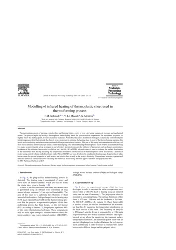
2.2 Thermoforming fibre reinforced thermoplasticsThermoforming [10, 15-18] is a process which is long established in the manufacture of thinwalled plastic containers and has enabled the manufacture of commercial products such asyoghurt pots and blister packs. It enables rapid transformation of semi-finished raw material intothe required design form by the combined action of heat and pressure. Relatively short formingtimes are made possible by the fast processing potential of thermoplastics [10]. The processcan be characterized in terms of the physical shape change and thermal history of the blankduring the complete process shown in Figure 1.The first stage involves heating the thermoplastic, pre-consolidated laminate to a temperatureabove the melt temperature of the thermoplastic matrix system, as shown in Figure 1. Deconsolidation occurs in the raw material blank during the heating phase, resulting from a releasein the stored elastic energy in the form of residual stress which originates from the initial rawmaterial compaction process [19]. The melt temperature of pure PPS is around 280ºC [5]. Meltphase thermoforming permits intra-ply and inter-ply slip, and at these elevated temperatures thedominant mode of deformation is slip parallel to the individual plies [16]. Therefore, processtemperature determination is of great importance because without sufficient melting of thethermoplastic matrix, forming can result in matrix cracking, fibre buckling, fibre bridging,wrinkling and therefore poor part quality and strength performance, especially in areas of sharpcontours and geometric detail.However, thermoplastic matrix material is also sensitive totemperature history, influencing induced residual stress, crystallinity and thus mechanicalperformance of the final part. Moreover, as the thermoforming process requires blanktemperatures above the matrix melt temperature, chemical reactions (cross-linking of molecularchains) can occur, and as noted previously can impact in-service performance andreprocessing.In the second stage, the material blank is indexed into the forming station (Figure 1) at a predefined temperature, usually just above the forming temperature to take into account thermalheat losses during indexing between stations. Once located in the forming station the blankmaterial is consolidated into a target shape by the closure of the matched die moulds. The roleof the mould is twofold.Firstly the mould re-consolidates the material plies and gives thefinished product its shape, thickness and surface finish. Secondly, the mould temperature is setat a predefined temperature to allow controlled part cooling and therefore solidification of thepart prior to part extraction from the mould, Figure 1. The final part thickness is governed by acombination of factors including mould tool geometry, ply layup, matrix chemical reactions andshrinkage. The mould tool design has a significant influence on part quality, including thicknessPage 6 of 24
variation as well as local and global part fibre volume fraction. Also, the level of tool compactionof the deconsolidated raw material blank has the potential to significantly influence the interlaminar shear strength of the part, if voids in the form of entrapped air, moisture and volatilesare not eliminated during the reconsolidation.The cooling rate after forming, normally determined by the blank temperature (x) and mould tooltemperature (y), is potentially one of the most important processing factors, significantlyinfluencing matrix material crystallinity and residual stress [20].For semi-crystallinethermoplastics, a higher cooling rate will tend to result in a lower peak crystallisationtemperature and lower crystallinity levels [20], and less matrix shrinkage. A high level ofcrystallinity will result in higher levels of static strength mechanical properties and chemicalresistance, but lower matrix fracture toughness properties.In addition, the mould tooltemperature will influence the cycle time (z) of the process as processed parts can only beextracted from the mould when they are structurally rigid and sufficiently cooled so that physicalhandling is possible and safe. Finally, x, y & z all significantly impact the energy footprint of theprocess.3.0 MethodologyThe preceding description indicates that there are several processing parameters which canhave an influence on final performance, but three of these initially appear to characterise theforming process and potentially have an influence on the performance of the formed parts. Theprocess parameters identified are:1. the raw material blank forming temperature,2. the mould tool temperature3. the mould tool consolidation (compaction metric).In this study the mould tool consolidation metric will be simplified into a 1D metric, describingthe ratio of the nominal closed tool thickness over the nominal raw material thickness. Hereinthis ratio will represent the tool design and is labelled as the mould tool consolidationcompaction ratio.To study any potential non-linear process effects, the three process parameters will beexamined at three magnitudes, a high level, a medium level and a low level.Page 7 of 24
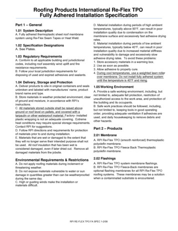
3.1 Manufacturing Process ParametersIn order to identify the magnitudes of the parameters for the study a series of preliminaryprocessing trials were carried out to establish the approximate limits for each. A DynamicMechanical Thermal Analysis (DMTA) was carried out to establish the temperature range forwhich thermoforming is possible, and simple trials heating and cooling samples helped toidentify de-consolidation and re-consolidation times. Samples were heated for varying timesand rapidly cooled to freeze the deconsolidated state so that the appropriate heating times for arange of temperatures could be established.These identified that a heating time of threeminutes was sufficient, and this was then used for all specimens. The trials also identified blankand mould temperatures and compaction ratios as described in the following three sections.3.1.1 Blank Forming temperature windowAnalysis of the DMTA data from the preliminary trials shows that the melting temperature (Tmelt)of the as-supplied material was approximately 285 ºC, as shown in Figure 2. However, the datashows that the material still exhibits a considerable modulus of 3.77 GPa at this temperature,which indicates that the material is too stiff for thermoforming. Thermoforming is only viable attemperatures where the modulus would tend to zero in a DMTA analysis. In this case it wasfound to be well above the melt temperature with the minimum level raw material blank formingtemperature being defined as 310 ºC. To establish the effect of elevated forming temperatureson the physical and mechanical properties of the formed parts, two further temperature levels of340 ºC and 370 ºC were selected.3.1.2 Mould temperature windowThe crystallisation kinetics of PPS are mainly influenced by the cooling rate of the processwhich is dictated by the raw material blank forming temperature (Tforming) and the mould tooltemperature (Tmould). To understand and quantify the relationships, the mould tool temperaturewill be experimentally examined at 50 ºC, 110 ºC and 170 ºC, again, based on simpleexplorative forming trials.3.1.3 Mould tool consolidation windowPre-consolidated laminates are supplied with a thickness which is dependent on ply layup andfibre volume fraction. The raw material laminate used in this work has an average thickness of1.80 mm, with maximum and minimum recorded raw material thickness values of 1.87 mm andPage 8 of 24
1.68 mm respectively. Preliminary re-consolidation trials were carried out to determine the rangeof consolidation compaction ratios (ratio of the nominal closed tool thickness over the nominalraw material thickness), with cross sectional images used to assess part consolidation and voidcontent. Three consolidation compaction ratios (CCR) of 1.00, 0.97 and 0.94 were determinedfor examination within the manufacturing trials. These compaction ratios were selected torepresent potential limits for the final part thickness achievable during the forming process fromthe initial variability in the raw material thickness. These compaction ratios represent closed toolthicknesses of 1.80, 1.75 and 1.70 mm respectively.3.1.4 Parameter Values for the experimentsThus considering three processing parameters at three levels requires a set of manufacturingtrials which follows a Taguchi three factor, three level orthogonal array, L9 [21-22]. Using thefractional factorial experimental design method in the present case, only nine manufacturingtrials are required to identify the dominant factors and their potential interactions.3.2 Performance ParametersTo identify interactions between processing parameters and performance characteristics eachcoupon set produced within the manufacturing trial was subsequently prepared for a range ofpost processing analysis and test. To define the relevant performance parameters an exemplarapplication is required.The manufactured coupons represent the local design (laminatestacking sequence and thickness) of an outboard wing rib vertical reinforcing strut, designed tocontrol rib web buckling under compression and shear loading. The thickness of therepresented structure is 1.8 mm and consists of a six ply, five harness satin woven carbon fibre(T300 JB) reinforced PPS pre-consolidated laminate with a stacking sequence of [(0,90)3]s, anda fibre volume content of 50 3%. Table 1 presents the supplied material properties of thelaminate and for the neat PPS matrix. There are many characteristics which define theperformance of a part throughout its life, from manufacture to disposal.To initiate theframework this study was limited to a set of seven key characteristics covering processingquality and cost, in-service strength performance, and end-of-life recyclability:1) Variation of Fibre Volume Fraction of the as-processed coupons,2) Variation of surface roughness of the as-processed coupons,3) Derived production cycle time of the employed process parameters,4) Flexural strength of the as-processed coupons,5) Degree of crystallinity of the as-processed coupons,6) Cold crystallisation temperature of the as-processed coupons, and finallyPage 9 of 24
7) Reprocessing melt temperature of the as-processed coupons,The measurement methods and rationale for selection of each of these will be expanded below.For each test type, specimens were water-cut from the manufacturing trial coupons andprepared as required for the individual tests.3.2.1 Volume fraction characteristicsFibre volume fraction (Vf) is a measure of fibre content relative to the total material make up andis thus an important indicator of process quality. Correct thermoforming of the raw material willproduce close tolerance part fibre volume fraction, equal to the original raw material fraction.Specimens were weighed in both air and methanol using a precision scale (Sartorius LA620P)and the density buoyancy method used to approximately determine the fibre volume fraction,assuming no voids and the individual density of the matrix and the fibre constituent materials.Although void content has not been taken into account when examining fibre volume fraction forthis work, Wakeman's findings [23] indicate that pressure forming methods can be usedeffectively to control void content minimizing their influence on finished part form properties suchas fibre volume fraction.Indicative figures for an equivalent material system using stampforming methods, show that void content in 3mm thick sheets of carbon fibre reinforced PA66started at 1.5% in the pre-consolidated state, rising to 15% during heating but finishing at 1%after forming[23].3.2.2 Surface roughness characteristicsSurface roughness (Ra) provides a measure of surface finish and ultimately final product quality.The finish derived using given thermoplastic based material and process combinationsinfluences downstream finishing activities such as surface pre-treatment, priming and paintingprocesses which are in turn, used to meet the joining and customer finish requirements for thepart. As the same mould surfaces were used for all manufacturing trials (ground nickel platedcarbon steel platens) the influence of the process parameters can be appraised. Surfaceroughness, measured in µm, is quantified here by vertical deflections of a stylus as it is tracedacross the specimen surface, herein using a Taylor-Hobson Talysurf.3.2.3 Derived production cycle timePage 10 of 24
Process cycle time is a key indicator of manufacturing recurring cost, and combined withtemperature data characterises the process energy footprint. It is particularly relevant at couponlevel analysis where other associated key recurring costs such as raw material, pre and postprocess setup and inspection times are necessarily constant.The derived production cycle times were determined by interrogating the individual temperaturedata for the trial specimens and identifying the additional dwell times due to the fixed blankheating and mould cooling times, removing these to calculate the optimised blank heat up andblank cool down times. The derived production cycle time t (seconds) was then calculated foreach trial based on the minimum time taken for thermal de-consolidation (ta), re-consolidation(tb), natural cooling in the mould (tc), and ambient part cooling (td) after mould ejection, to a safehandling temperature (30ºC in this case), and the summation of the individual times thus:t t a tb t c t d(1)3.2.4 Flexural strength characteristicsMaximum flexural strength (σf) is an important indicator of the in-service static strength of theformed part and an indicator on the quality of reconsolidation during forming. The test couponswere based on the ASTM D790 standard.3.2.5 Crystallinity and melt temperature characteristicsDifferential Scanning Calorimetry (DSC) was used to determine the degree of crystallinity, coldcrystallisation temperature and reprocessing melt temperature of the processed manufacturingtrial coupons. The degree of crystallinity is measured as it is an important indicator of materialstatic strength and fracture toughness, and also the level of irreversible cross-linking chemicalreaction which has occurred during processing. The cold crystallisation temperature is animportant metric with respect to the in-service temperature ceiling, although it is not the ultimatetemperature limit of the matrix material, service above this temperature will alter the crystallinityand thus part behaviour. The reprocessing melt temperature is also measured, indicating thelevel of irreversible chemical reaction during processing.The properties were measured following the ISO 11357 standard with a 10 mg specimen over atemperature range of 20 to 310 ºC, at a heating rate of 20 ºC per minute. Repeat measurementswere carried out for each manufacturing trial coupon, and the mean values calculated. The areaPage 11 of 24
of the melting peak and cold crystallisation peak ( H) in the specific heat flow versus specimentemperature curves, were determined to calculate the degree of crystallinity (χ), in accordancewith Equation 2:χ H(1 W f ) H f(2)where Wf is the fibre weight fraction of the processed material, and Hf represents the enthalpyof fusion for 100% crystalline PPS, taken as 112 J/g [24].It is important to note that the final degree of crystallinity (χfinal) does not represent the crystallinelevel of the processed coupon, since the samples experience a re-crystallisation during the DSCcharacterisation.Thus the cold crystallinity (χcold)i.e. that measured at 20 ºC should besubtracted from the final measured crystallinity. Therefore, the degree of crystallinity for the asprocessed coupons is calculated using Equation 3:χ c χ final χ cold(3)3.3 Test ProceduresThe thermoforming trials were carried out using a ten ton laboratory platen press. The pressconsists of precision ground nickel plated carbon steel platens with independent platentemperature control.consolidated thickness.The platen press enabled flat plate thermoforming with constantIn addition to temperature control, coupon thickness control wasmaintained by incorporating precision gr
computational modelling and reduce dependence on experimental methods in product development. Further, material suppliers provide limited physical properties or processing values which seldom go beyond their own requirements for quality control purposes. . thermoforming family of processes, such as matched die forming, rubber thermoforming,