Transcription
Installation al ThermostatNOTE: Read the entire instruciton manual before starting the TPUMPMULTI-STAGEForm: IM-TSTAT-16Cancels:PROGRAMMABLEPrinted in U.S.A.Catalog No. 13TS-TA42
Table Of ContentsPREPARATIONREMOVE OLD THERMOSTATINSTALL BACKPLATE & WIREWIRING DIAGRAMSCALIBRATIONTEST OPERATIONTROUBLESHOOTINGCAUTION23458910Follow Installation Instructions carefully.DISCONNECT POWER TO THE HEATER AIR CONDITIONER BEFORE REMOVINGTHE OLD THERMOSTAT AND INSTALLINGTHE NEW THERMOSTAT.Replacement Components DivisionWARNINGCarrier Corporation 4/01This device complies with Part 15 of the FCC rules.Operation is subject to the following 2 conditions:(1) This device may not cause harmful interference,and (2) This device must accept any interferencereceived, including interference that may causeundesired operation.Page 1
STEP #1PREPARATIONProper installation of the thermostat will beaccomplished by following these stepby step instructions. If you are unsureabout any of these steps, call a qualifiedtechnician for assistance.Assemble tools as shown below.Flat BladeScrewdriverWire cutter& StripperDrill with 3/16inch Drill Bit(when not usingj-box)Make sure your Heater/Air Conditioneris working properly before beginninginstallation of the thermostat.Carefully unpack the thermostat.Save the screws, wall anchors, andinstructions.Page 2
STEP #2REMOVE OLD THERMOSTATTurn off the power to the Heating/AirConditioning system at the main fusepanel. Most residential systems havea separate breaker for disconnectingpower to the furnace.Remove the cover of the old thermostat.If it does not come off easily check forscrews.Loosen the screws holding the thermostatbase or subbase to the wall, and lift away.Disconnect the wires from the oldthermostat. Tape the ends of the wiresas you disconnect them, and mark themwith the letter of the terminal for easyreconnection to the new thermostat.Keep the old thermostat for referencepurposes, until your new thermostat isfunctioning properly.Page 3
STEP #3INSTALL BACKPLATE & WIRERemove the backplate connector from therear of the thermostat. Install wires as directedbelow. When finished, snap thermostat on tobackplate.If the terminal designations on your oldthermostat do not match those on thenew thermostat, refer to the chart below,or the wiring diagrams that follow.Wire from theold thermostatterminal markedFunctionInstall on thenew thermostatconnector markedGG or FFanY1, Y or CCoolingW1, W or HHeatingY1W1,O,BRh, R, M, Vr, APowerCCommonC*RO/BRev. ValveW1,O,B**Y22nd Stage CoolY2W22nd Stage HeatW2RS 5Remote Sensor 5vdcRSRemote Sensor SignalRS GRemote Sensor GroundCK1Dry Contact Switch 1CK2Dry Contact Switch 2* C may not be used on all systems.** O/B is used if your system is a Heat Pump.Page 4
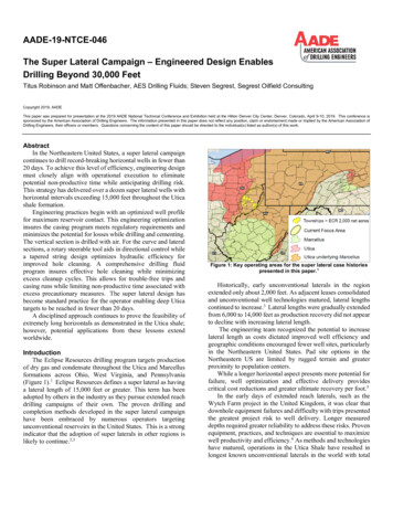
Sample Wiring Diagrams5 Wire, 1 Stage Cooling, 1 Stage Gas HeatOW2 Y2 R W1 Y1 GResidential Gas or Electric Heat *,Electric Cool, split systems & packageunitsCThermostatLE24 vac commonCfan relaycompressor relayY1GO1st stage heat circuit24 vac return* If using electric heat this option must beselected on during advanced setup.W1RY2W24 Wire, 1 Stage Cooling, 1 Stage Gas HeatOW2 Y2 R W1 Y1 GResidential Gas or Electric Heat *,Electric Cool, split systems & packageunitsCThermostatLECfan relaycompressor relayGY1O1st stage heat circuit24 vac return* If using electric heat this option must beselected on during advanced setup.Page 5W1RY2W2
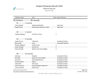
Sample Wiring Diagrams6 Wire, 2 Stage Cooling, 1 Stage HeatOW2 Y2 R W1 Y1 GResidential 2 Stage Cooling, withGas or Electric Heat*CThermostatLE24 vac commonCfan relaycompressor relayY1GO1st stage heat circuit24 vac return2nd stage compressor relay* If using electric heat, this option mustbe selected during advanced setup.W1RY2W26 Wire, 1 Stage Cooling, 2 Stage HeatOW2 Y2 R W1 Y1 GCResidential & commercial 1 Stage Cooling,with 2 Stage Gas or Electric Heat*ThermostatLE24 vac commonCfan relaycompressor relayY1GO1st stage heat circuit24 vac returnW1RY22nd stage heat circuitPage 6W2
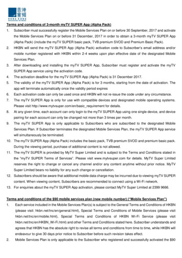
Sample Wiring DiagramsCommercial Gas or Electric Heat ***,Electric Cool, split systems & package unitsincluding Commercial Heat Pumps **7 Wire, 2 Stage Cooling, 2 Stage HeatOW2 Y2 R W1 Y1 GCThermostatLE24 vac commonCfan relaycompressor relayY1GO1st stage heat circuit24 vac return2nd stage compressor relay2nd stage heat circuit** Commercial heat pumps do not have*** If using electric heat, this option mustthe heat pump turned on in advanced setup.be selected on during advanced setup.W1RY2W25 Wire, 1 Stage Cooling, 1 Stage Heat - Heat Pump*OW2 Y2 R W1 Y1 GNo auxiliary heat, residential Heat Pumps ,split systems & package unitsCThermostatLE24 vac commonCfan relaycompressor relayGY1reversing valveOW124 vac return* If using residential heat pump, this optionmust be selected on during advanced setup.RY2W2Page 7
Sample Wiring Diagram6 Wire, 1 Stage Cooling, 2 Stage Heat, Heat Pump *OW2 Y2 R W1 Y1 GCMost residential split and package heat pumpswith auxiliary heatThermostatLE24 vac commonCfan relaycompressor relayY11st stage heat circuitGOW124 vac returnRY22nd stage heat circuitW2* The heat pump option must be selectedon during advanced setup.CalibrationEvery thermostat is calibrated before it leaves the factory.Under normal circumstances there will never be a need torecalibrate the thermostat again.To accommodate special needs, the thermostat may be recalibratedfollowing these steps:1. While holding the mode button in, press the down button for2 seconds. After all the icons in the display appear, releasethe buttons.2. Press the mode button.3. Press the up or down buttons until the flashing numberequals the current room temperature.4. Press the mode button to return to normal operation.Page 8
STEP #4TEST OPERATIONTurn the power on to the Heating/AirConditioning system.Press the MODE button repeatedly untilthe HEAT icon appears on the display.Press the Up or Down buttons until the settemperature is 10 degrees above roomtemperature. The furnace should turn on.Press the MODE button repeatedly untilthe COOL icon appears on the display.Press the Up or Down buttons until the settemperature is 10 degrees below roomtemperature. The air conditioner shouldturn on. NOTE: Most equipment has atime delay of 5 minutes between coolcycles. This feature is defeatable on thethermostat. Consult the Owner's Manualunder Setup, cycles per hour.Press the MODE button to OFF. Pressthe FAN button to Fan On. The fanshould turn on and run continuously.Page 9
TROUBLESHOOTINGSYMPTOM: When using 4 wires (R, G, W, Y),the air conditioning or heat equipment triesrepeatedly to turn on, but cannot. Attimes the display dims or disappears.CAUSE: There is not enough power availableto "power share".REMEDY: Connect a 270 ohm, 10 watt powerresistor at the furnace as shown below.For Problem A/CRGWYFor Problem HeatCRTR300-10wGWYCTR300-10wSYMPTOM: The air conditioning does notattempt to turn on.CAUSE: The compressor timer lockout mayprevent the air conditioner fromturning on, for a period of time.REMEDY: Consult the Owner's Manual inthe Setup section to defeat thecycles per hour and compressortimeguard.SYMPTOM: The display is blank.CAUSE: Lack of proper power.REMEDY: Make sure power is turned on tothe furnace and that you have 24vacbetween R & W. If C is used, 24vacbetween R & C.Page 10
TROUBLESHOOTINGSYMPTOM: The air conditioning does notattempt to turn on.CAUSE: The cooling setpoint is set toohigh.REMEDY: Consult the Owner's Manual inthe Setup section to lower thecooling setpoint limit.SYMPTOM: The heating does not attemptto turn on.CAUSE: The heating setpoint is set toolow.REMEDY: Consult the Owner's Manual inthe Setup section to raise theheating setpoint limit.Page 11
TROUBLESHOOTINGSYMPTOM: When controlling a residential heatpump, and asking for cooling, the heatcomes on.CAUSE: Heat pump is not selected "on" in theAdvanced Setup.REMEDY: Select heat pump on during AdvancedSetup programming. Consult the Owner'sManual.SYMPTOM: When calling for cooling, boththe heat and cool come on.CAUSE: The Advanced Setup is configuredto control a heat pump, and the hvacthe thermostat is controlling is a"conventional" (non heat pump)system.REMEDY: Consult the Owner's Manual inthe Advanced Setup section to turnoff the heat pump.STARTSTATCCPB501TSTATBBPB501P474-1050Tested to Complywith FCC StandardscFCFOR HOME OR OFFICE USE4Z95P/N 88-335Page 12
SYMPTOM: The air conditioning does not attempt to turn on. CAUSE: The compressor timer lockout may prevent the air conditioner from turning on, for a period of time. REMEDY: Consult the Owner's Manual in the Setup section to defeat the cycles per hour and compressor timeguard. R G W Y C TR300-10w R G W Y C TR300-10w SYMPTOM: The display is blank.