Transcription
CHAPTER3Layers, Colors, Linetypes,and Properties67LEARNING OBJECTIVESLayers are an essential concept and need to be introduced before a serious drawing isattempted. In this chapter, we introduce layers and discuss the following: What are layers? Why use them? Creating and deleting layers Making a layer current Assigning layer colors Index color True color Color Books Layer Freeze/Thaw Layer On/Off Layer Lock/Unlock Loading and setting linetypes Properties Palette Match Properties Layers toolbarUp and Running with AutoCAD 2012: 2D and 3D Drawing and Modeling. 2012 Elsevier Inc. All rights reserved.CH003.indd 676/29/2011 10:05:19 AM
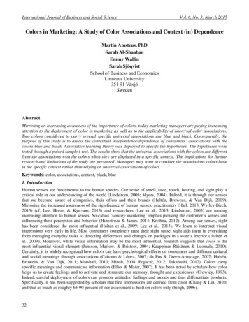
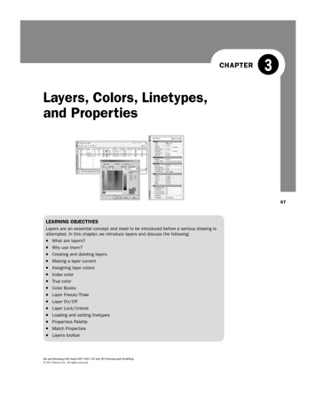
LEVEL 1Chapters 1–10Here, you learn all the remaining tools to begin creating a floor plan, which we start at theend of the chapter.Estimated time for completion of chapter: 3 hours (lesson and project).3.1 INTRODUCTION TO LAYERSLayers are our first major topic after the previous chapters of basics. It is a very importantconcept in AutoCAD, and no designer or draftsperson would ever consider drawing anythingmore complex than a few lines without using them.What Are Layers?“Layers” is a concept that allows you to group drawn geometry in distinct and separatecategories according to similar features or a common theme. This allows you to exercisecontrol over your drawing by, among other things, applying properties to the layers, suchas assigning colors and linetypes. You can also manipulate each individual layer, making itvisible or invisible for clarity, as well as being able to lock them to prevent editing.For example, all the walls of a floor plan will exist on the “Walls” layer, all the doors onthe “Doors” layer, windows on the “Windows” layer, and so on. You can think of layers astransparency sheets in an anatomy textbook, with each sheet showing a unique and distinctcategory of data (skeleton, muscle, circulatory system, etc.), but when viewed all at once theyshow the complete picture of a person. Similarly, in AutoCAD, there can be any number oflayers, with all of them holding their respective data and combining into the complete design.Why Use Them?68As just stated, the key word here is control. If all your geometry were lumped together onone layer, as some beginners do, then whatever you do to one set of objects, you do to all;certainly not what you want. It is very important that you learn about layers early in yourAutoCAD education, and apply them right away to your first real drawing.Let us take a look at the Layers Properties Manager. This is AutoCAD’s Layers dialog box,where everything important related to layers happens. Open a new file and, if you decideto use toolbars, also bring up the Layer toolbar. We take a closer look at that toolbar inSection 3.3, but for now you need only the icon that calls up the Layers Property Manager.Once you call up the layers property manager, you will see Figure 3.1Examining the dialog box from left to right, notice the filters taking up some room on the left.We need not talk about filters until Chapter 12, and you can actually minimize that whole areaby clicking the arrows. To the right of the filters, notice the main category headers suchas “Status,” “Name,” “On,” and “Freeze.” Below the categories you find the only existing layerthus far, 0, and its properties. Notice that it is white with a “continuous” linetype. Above thecategories are some action buttons for creating and deleting layers, which we cover next.Creating and Deleting LayersAssuming you are starting from a blank file, each new layer initially needs to be typed inaccording to what you (or the company you work for) require. To do that, you first need toCH003.indd 686/29/2011 10:05:19 AM
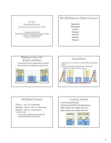
CHAPTER 3Layers, Colors, Linetypes, and Proper tiesFIGURE 3.1AutoCAD 2012 Layer Properties Manager.click on the 0 layer to make sure it is highlighted with the blue band. Then press the NewLayer icon at the top of the layer box (two icons to the left of the red X), which looks likea sheet of paper with a sparkle next to it. You can also hold down the Alt key and press N.Either way, once you do that, a new band saying Layer 1 appears. Just type in your new layername followed by Enter, and a new layer is created. Here are some helpful tips: If you notice that you made a spelling mistake after you already pressed Enter, you canjust click back into the layer name once or twice until the cursor enters Edit mode andretype.Do not attempt to change the 0 layer’s name. It is the default layer and cannot be deletedor renamed.If you want to delete a layer (perhaps an accidentally made one), simply highlight the layer,and click the red X icon, or press Alt-D. If the layer contains nothing, it will be deleted.69Following this procedure, create the following three layers: A-DoorsA-WallsA-WindowsWhat you should see is shown in Figure 3.2. The letter A in front of each layer simply meansArchitectural.Making a Layer CurrentThe current layer is the active layer on which you can draw at any given moment. You arealways on some layer (even if you are not immediately sure which one exactly). So, logically,if you are about to draw a wall, you should be on the A-Walls layer and so on. To specifywhat layer to have as current, either click on the green check mark button, to the right of thered X, or double-click on the layer name itself. At the very top left of the Layers dialog box itsays “Current layer:” followed by the name of the layer. Check there if you are unsure what iswhat. For now, go ahead and make A-Walls the current layer.Assigning Layer ColorsAssigning colors to layers is very important and should be done as you create them or soonafter. The reasons to have color are twofold. On the most basic level, a colorful drawing is morepleasant to look at on the screen, but more important, it is easier to interpret and work with. If,CH003.indd 696/29/2011 10:05:19 AM
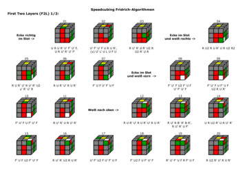
LEVEL 1Chapters 1–10FIGURE 3.2Layer Properties Manager with three new layers.for example, your walls are green and you keep this in mind, then your eye is able to quickly seeand assess the design. Likewise, yellow doors are easy to spot. This color separation greatly aidsin drafting. Imagine a scenario where your building floor plan is made up of all white lines;you would be unable to tell one line from another. As that drawing grew more complex, all thelines would melt into one monochrome mess. Finally, colors are assigned pen thicknesses (anadvanced topic) and contribute to more professional-looking output. We address this in Level 2.70To assign colors, let us turn our attention back to the Layers dialog box. Highlight, byclicking once, layer A-Walls. Now, follow the blue ribbon across until you see a box with theword white next to it. It will be under the Color column. Click on it, and the Select Colordialog box appears, as seen in Figure 3.3.FIGURE 3.3Select Color, Index Color.CH003.indd 706/29/2011 10:05:19 AM
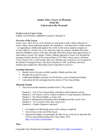
CHAPTER 3Layers, Colors, Linetypes, and Proper tiesINDEX COLORLet us take a tour of this Index Color tab. The two large 24 5 stripes of colors you immediatelysee at the top make up the AutoCAD Color Index (ACI), and it contains 240 colors. Do not be tooquick in selecting one of those right away. Take a look below; there are two smaller color stripes.The rainbow-like stripes 1 through 9 are the ones in which we are most interested. If you take aclose look, they are the primary colors and the 240 colors above them are just different shades ofthe primaries. You should always use up those nine colors first—they are very distinct from eachother—and only then move on to the others. Also this makes setting pen weights easier laterdown the road, as you need not scroll through dozens of colors to find the ones you used.The colors from left to right are Red Yellow Green Cyan (not Aqua) Blue Magenta(not Maroon), then White and two shades of Gray, 8 and 9. The color stripe below thatcontains just additional shades of gray, and we do not need them for now. So, finally, picka color for the A-Walls layer (green is what many architects use for walls), click on it, thenpress Enter; you are taken back to the Layers dialog box to assign more colors to more layers.Yellow is recommended for A-Doors and red for A-Windows.TRUE COLORThere is more to colors, of course. Go back to the Select Color dialog box. Now, click thesecond tab, called True Color (Figure 3.4). Here is where some experience in graphic designmay come in handy.The main color window you are looking at now contains over 16 million colors and should befamiliar to you if you use Photoshop, Illustrator, PaintShop , or any of those types of designprograms. You can now move your mouse around, selecting colors based on the HSL method.HSL stands for Hue (the actual colors, moving across), Saturation (moving up or down), andLuminance (brighter or darker, moving the slider up or down next to the main window). Youmay also use the RGB (red, green, blue) model of color selection by using the drop-downselector at the upper right (Figure 3.5). Whichever color you settle on is shown by both colormodels. Designers rarely use these colors for 2D work (where you want objects to be bright andvisible), but do pick these more subtle colors for realistic-looking 3D models.FIGURE 3.4FIGURE 3.5Select Color, HSL.Select Color, RGB.CH003.indd 71716/29/2011 10:05:20 AM
LEVEL 1Chapters 1–10COLOR BOOKSHere is where things get even fancier. Color Books are Pantone colors. If you are an architector an interior designer, you already know what these are. If you are shaking your head andhave never heard of Pantone, do not worry about it, chances are you will not need to usethem. Just to try however, scroll through the palettes and select a color. Figure 3.6 is a screenshot of the Color Books tab.72FIGURE 3.6Select Color, Color Books.Layer Freeze/Thaw and On/OffHere, we come to a very important part of the Layers dialog box. Freeze and Thaw are oppositesof the same command, one that makes a layer appear or disappear from view. The commandfreezes or thaws the layer for the entire drawing. Pick a layer, highlight it, follow the bandacross to the Freeze column and underneath you will find a yellow sun icon. If you click on it,that layer “freezes” and the icon becomes a blue snowflake. Clicking again undoes the action.So what does freeze mean? It makes the layer (or more precisely all the objects on that layer)disappear from view, but remember, they are not deleted only invisible. You will use this featureroutinely in drawings to control what is displayed. The On/Off feature represented by thelightbulb (yellow to blue and back) is essentially the same as Freeze/Thaw, with some subtle(and minor) details, so we do not go into them. You can use either method; although stay withFreeze/Thaw just to keep things consistent.Layer Lock/UnlockThis layer command, represented by the padlock, does exactly that; it locks the layer so youcannot edit or erase it. The layer remains visible but untouchable. The unlocked layer’s iconis blue and looks “unlocked,” while a locked layer’s padlock turns yellow and changes to a“locked” position. To let you know which layers are locked, the layers fade somewhat, so youcan tell them apart from non-locked geometry. You can control the level of this fading via aslider on the Ribbon. Go to the Home tab, and drop down the arrow in the Layers category.CH003.indd 726/29/2011 10:05:20 AM
CHAPTER 3Layers, Colors, Linetypes, and Proper tiesYou see a slider that says “Locked layer fading.” Use it to make the locked layers darker orlighter to your liking.Experiment with everything mentioned thus far to get a feel for layer controls. When done,make sure everything is reset (not locked or frozen) and click on the X in the upper corner ofthe layer box to close it.3.2 INTRODUCTION TO LINETYPESLinetypes are the different lines that come with AutoCAD. As a designer, architect, orengineer, you may need a variety of lines to convey different ideas in your design. Just as inhand drafting, where you create Dashed, Hidden, Phantom, and other line types to showcabinets, demolition work, or hidden geometry in part design, in AutoCAD you load thelines and use them as necessary.The idea here is to load them all in the beginning and then assign the linetypes toeither a layer or sometimes just a few items. You can also load them as needed, but it isrecommended to get this out of the way so you have them at your fingertips. The procedureto do so is as follows:Step 1. Type in linetype and press Enter or choose Format Linetype from thecascading menu. The Linetype Manager (Figure 3.7) appears. If it is full of linetypes,it means they have been loaded earlier. If not, and the Linetype Manager is empty, goon to Step 2.Step 2. Press Load The Load or Reload Linetypes box comes up (Figure 3.8).73FIGURE 3.7FIGURE 3.8Linetype Manager.Load or Reload Linetypes.Step 3. Position your mouse in the white empty space between the two columns (Linetypeand Description) of the Load or Reload Linetypes box and right-click. The Select All/Clear All menu appears.Step 4. Press Select All and every linetype in the left column turns blue (selected).Step 5. Press OK (and possibly a Yes to All as well) and the dialog box disappears. All thelinetypes are loaded now, so press OK again in the Linetype Manager and you aredone.CH003.indd 736/29/2011 10:05:21 AM
LEVEL 1Chapters 1–10We can now use the loaded linetypes and assign a linetype to a layer. Go back to the Layersdialog box:Step 1. Create a new layer called Hidden and assign a linetype to it (the “Hidden” linetype,naturally).Step 2. Make sure the Hidden layer is highlighted with the blue bar, and move your mouseto the right until it matches up with the header category Linetype. It should sayContinuous right now.Step 3. Click on the word Continuous and the Select Linetype (Figure 3.9) dialog box comesup with all your linetypes preloaded. If we did not load them earlier, the box wouldbe practica
Color Books Layer Freeze/Thaw . AutoCAD education, and apply them right away to your fi rst real drawing. Let us take a look at the Layers Properties Manager. This is AutoCAD’s Layers dialog box, where everything important related to layers happens. Open a new fi le and, if you decide to use toolbars, also bring up the Layer toolbar. We take a closer look at that toolbar in Section 3.3 .