Transcription
Failing to Fail: Achieving Success inAdvanced Low Power Design using UPF1RickKoster, 2John Redmond,and 3Shreedhar Ramachandra1MentorGraphics Corporation2Broadcom Corporation3Synopsys Inc.International Symposium on Low Power Electronics and Design
UPF OverviewRick KosterMentor GraphicsInternational Symposium on Low Power Electronics and Design
Agenda UPF Overview– Low Power Management Concepts– What is UPF– Power Management Structures– Power Management Behavior3
Power Management Concepts Power Gating:– Shutting off power to portions of the design (PowerDomains) to eliminate leakage power consumption Multi Voltage Designs:– Organizing the design into different voltage domainsas a function of performance to minimize dynamicand static power consumption Voltage and Frequency Scaling– Dynamically tune parts of the design to meetperformance goals with minimum power Power Management requirements– Isolation, Level Shifting, State Retention, Switching4
What is UPF? An Evolving Standard––––Accellera UPF in 2007 (1.0)IEEE 1801-2009 UPF (2.0)IEEE 1801-2013 UPF (2.1)IEEE 1801A-2014 UPF (2.2) For Power Intent Based upon TCL– Tcl syntax and semantics– Can be mixed withnon-UPF TCL And HDLs– SystemVerilog, Verilog, VHDL– To define power For Verificationmanagement– Simulation or Emulation– To minimize power– Static/Formal Verificationconsumption And for Implementation– Through control of leakage– Synthesis, DFT, P&R, etc.5
Power Management Structures Power DomainsDomain Interfaces (ISO/LS)RetentionSupply SetsSupply Ports/NetsPower Switches6
Power Domains A collection of instances that are treated as agroup for power-management purposes. A Power domain exists within a logical scope– UPF and HDL identifiers must be unique within thescope– All UPF commands are executed within the currentactive scope A power domain can have associated with itisolation strategies, retention strategies andlevel shifter requirements7
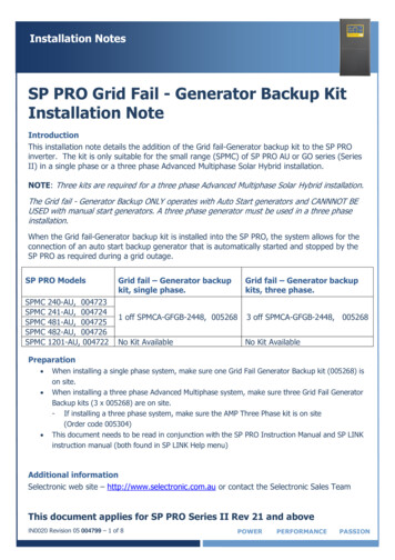
Power Domainscreate power domain DUT PD –include scopecreate power domain C1 PD -elements {CPU1}create power domain C2 PD -elements {IP1 CPU2}C2 PDDUTC1 PDIP1CPU 2CPU1MemorycacheBUS/FabricP1P2P3IP2Power CTRLDUT PD8
Supply Sets Represent a collection of supply netsthat provide a power source.Supply NetsSupply Set– Consists of a set of up to 6 ldeeppwellMain power, ground, nwell, pwell, deepnwell,deeppwell– One supply net per (required) function– Electrically complete model of a powerdistribution network in a domain:Functionscreate power domain PD u1 –include scopecreate power domain PD u11 – elements {U1/U11}create power domain PD u12 –elements {U1/U12}power, ground, etc. Power domains have a few predefinedsupply sets: primary, default isolation,PRU1and default retention Supply sets can be associated withone another to model supplyconnections abstractlyIPIRPU11L1L2IRU12L3L4L59
Domain Interfaces Power gating can cause electrical and logicalproblems to adjacent domains.– Isolation is used to prevent these problems.– Isolation cell: An instance that passes logic values duringnormal mode operation and clamps its output to some specifiedlogic value when a control signal is asserted. Multi voltage designs can also experienceproblems– Level shifters are used to maintain signal integrity. Level shifter cell: An instance that translates signal values froman input voltage swing to a different output voltage swing.10
Retention/Repeaters Device operation may require the use of flipflops or memories that preserve state during adomain’s power down. Preserving state is achieve through the use ofUPF retention.– Retention: Enhanced functionality associated withselected sequential elements or a memory such thatmemory values can be preserved during the powerdown state of the primary supplies.11
Supply Ports/Nets Power Domain supply sets consist of supplynets that eventually are driven by supply ports Supply ports and nets are defined as objects ofsupply net type UPF package defines supply net type as:typedef enum(OFF 0,UNDETERMINED, PARTIAL ON, FULL ON) statetypedef struct packed {state state;int voltage; // voltage in microVolts} supply net type;12
Power Switches A power switch is a design element thatconditionally connects input supply nets to anoutput supply net A UPF switch can be on or off or partially on The state of the switch is set by Booleanfunctions of the control ports Match input voltage propagates to output (on) No Match output port disabled (off) Either power or ground can be switched13
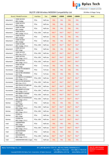
set design top U1create power domain PD u1 –include scopecreate power domain PD u11 –elements {U1/U11}create power domain PD u12 –elements {U1/U12}create supply net sw1 out netcreate power switch SW1 \-domain PD u1 \-output supply port {swout sw1 out net} \-input supply port {swin PD u1.primary.power} \-control port {swctrl swCtl1} \-on state {SWon swin swctrl} \-off state {SWoff !swctrl}create supply set sw1 ss \-function {power sw1 out net} \-function {ground PD u1.primary.ground}associate supply set sw1 ss-handle PD u11.primaryassociate supply set PD u1.primary \-handle PD u11.default retentionassociate supply set PD u1.primary \-handle PD u11.default isolationset isolation iso pd u11 –domain PD u11 \-location self –clamp value {1} \-applies to outputsset retention ret pd u11 –domain PD u11 \-elements {U11/ret1} \-save signal {U11/ret n} high \-restore signal {U11/ret n low}UPF StructureCommand examplePIRIPRU1SW1RPIISOU12U11RET1L2L3L4RET514
create supply net sw2 out netcreate power switch SW2 \-domain PD u2 \-output supply port {swout sw2 out net} \-input supply port {swin PD u1.primary.power} \-control port {swctrl swCtl2} \-on state {SWon swin swctrl} \-off state {SWoff !swctrl}create supply set sw2 ss \-function {power sw2 out net} \-function {ground PD u1.primary.ground}associate supply set sw2 ss-handle PD u12.primaryassociate supply set PD u1.primary \-handle PD u12.default retentionassociate supply set PD u1.primary \-handle PD u12.default isolationset isolation iso pd u12 –domain PD u11 \-location self –clamp value {0} \-applies to outputsset retention ret pd u12 –domain PD u11 \-elements {U12/ret1} \-save signal {U12/ret n posedge}-restore signal {U12/ret n negedge}UPF StructureCommand 15
Behavior Supply set Power States Simstates Power Domain States16
Supply Sets Power States The power states of a supply set describe theexpected combination of states of the supplynets in the supply set– The state can be defined by a logic expression andmay include supply expression– State holds when logic expression is TRUE– A power state defines the legal values of supply setfunctions when in that state– Also may include a simstateadd power state PdA.primary-state GO MODE {–logic expr {SW ON } –simstate NORMAL-supply expr {{power {FULL ON 0.8}}&& {ground {FULL ON, 0}} && {nwell {FULL ON 0.8}}}-state OFF MODE {–logic expr {!SW ON} –simstate CORRUPT}-supply expr {power {OFF}}17
Simstates Simstate defines precise simulation semantics in thisstate. That is, the expected behavior of the cellsconnected to this supply set. CORRUPT– Combinational outputs corrupted– Sequential state/outputs corrupted CORRUPT ON ACTIVITY– Combinational outputs maintainedas long as inputs are stable– Sequential state/outputs corrupted CORRUPT ON CHANGE– Combinational outputs maintainedas long as outputs are stable– Sequential state/outputs corrupted NORMAL– Combinational logic functions normally– Sequential logic functions normally– Both operate with characterized timing CORRUPT STATE ON ACTIVITY– Combinational logic functions normally– Sequential state/outputs maintained aslong as inputs are stable CORRUPT STATE ON CHANGE– Combinational logic functions normally– Sequential state/outputs maintained aslong as outputs are stable18
Power States of a Power Domain A power domain is designed to have a set ofallowable states in which it can operate. The domain power states describe theallowable set of states for a domain. Eachstate is defined by a logic expression– Logic expressions can be created with: States of supply setsLogic port and net valuesSubdomain power statesInterval Functions19
Attributes Characteristics of a port or design element Used to identify power supplies for ports– set port attributes -ports Out1 -attribute \{UPF related power port “VDD”} Used to specify constraints for IP usage:– set port attributes –ports {logic port} –attribute \{UPF clamp value “1”} Used to specify structure and behavior– set design attributes –elements ALU1 –attribute \{UPF is leaf TRUE}– set design attributes –elements ALU1 –attribute \{UPF retention required}20
Summary UPF captures power intent of a design– Power gating, multiple voltage, dynamic voltage andfrequency scaling, isolation, retention, level shifting UPF works with HDL– Verilog, VHDL and SystemVerilog UPF guides verification and implementation UPF is an evolving standard––––Accellera UPF in 2007 (1.0)IEEE 1801-2009 UPF (2.0)IEEE 1801-2013 UPF (2.1)IEEE 1801a-2014 UPF (2.2)21
UPF For ASIC DesignJohn Redmond *Broadcom Corporation* Slides contributed by Sushma Honnavara-PrasadInternational Symposium on Low Power Electronics and Design
Agenda Introduction– How power intent is realized in silicon– Leaf Cells and macro models Soft IP modeling– Successive refinement– Constraints, configuration, implementation SoC integration– Hierarchical UPF composition– Supply network construction– System power states and transitions23
Introduction Power intent is captured through UPF, HDL and Library UPF realizes:– Supply network specification power/ground/nwell/pwell/deepnwell/deeppwell Macro and IO power connectivity On-chip power switch specification– Power domain specification Identify a standard cell region, supply availability in a region– Strategies and their implementation Dictates inference of isolation cells, level shifters, repeaters and retention cells Leaf cell/macros need models to identify supply pins– Liberty (.lib) provides UPF attributes– LEF identifies power/ground/signal pins– 1801-2013 enables cell and macro modeling24
Leaf Cells An instance that has no descendants orhas UPF is leaf cell attribute on it Typically refer to standard cells––––HDL – simulation modelUPF – low power cells specificationLiberty – implementationLEF – physical design Attributes of interest–––––supply vs signal pinssupply propertiescell attributespin attributesfunction attributes UPF specifies either explicit, implicit orautomatic supply connectivity to leaf cellstop modulesub modulesubmodulesub moduleleafcell (INVX1) {.pg pin (VDD) {.pg pin (VSS) {.25
Macros Also called IPs, a piece offunctionality optimized forpower/area/performance– Soft macros – handed off assynthesizable HDL (technologyagnostic)– Hard macros – handed off asLEF/GDS (technology specific) Also a leaf cell UPF is macro cell attribute allowsthe model to be recognized as partof lower boundary of the domaincontaining the instance Can be modeled as:Example of a hard macro –Embedded SRAM– UPF Power Models– Liberty models26
IP Modeling UPF Power models– Regular UPF commands enclosed betweenbeing power model and end power model– Applied on an IP instance using apply power model command– Models power states, port attributes, isolation etc. Liberty models– Pin, supply and cell based attributes available– switch pin, pg pin, is macro cell etc. Verilog simulation models– Model supply as logic functions27
Successive Refinement IP provider IP Source IP licensee Integrator Technologyspecificimplementation28
Constraints Identify "atomic" power domains in the design– Indivisible, but can be merged during implementationcreate power domain PD IP1 –elements { u inst ip1 } -atomic Identify state elements to be retained during power down– Type of retention flop, controls not specifiedset retention elements PD IP1 ret elem –elements ip1 elem list– ip1 elem list list of elements that need to be retained in PD IP1 Identify isolation clamp values on ports– Isolation controls not specifiedset port attributes –elements ip1 elem list -applies to outputs \-clamp value 0 Specify legal power states and sequencing between them– Supply ports, actual voltages not specifiedadd power state PD IP1 –domain \-state { nom -logic expr { (ss ip1 nom) && {ss ip2 ! off) }29
Configuration Uniquify/finalize power domains based on RTL configuration– Number of instances generated determined by RTL parameters Merge power domainscreate composite domains PD IP –subdomains { PD IP1 PD IP2 } Create the required power-management ports (pwr/iso/ret)create logic port pwronin –direction increate logic port iso–direction in Create isolation strategies to fulfill isolation requirementsset isolation sw iso c0 –domain PD IP -applies to outputs \-clamp value 0 –isolation signal iso \-isolation sense high –location self Create retention strategies to fulfill retention requirementsset retention sw ret –domain PD IP –elements ip1 elem list \–retention condition { ret } Update power states and power transitionsadd power state PD IP –domain –update \-state { nom-logic expr { pwronin } }30
Implementation Create supply ports and netscreate supply port VDD1 –direction increate supply net VSS –domain PD SUB1 -reuse Update supply set functionscreate supply set ss ip1 –update –function {power VDD1} \-function {ground VSS} Update power states with supply valuesadd power state ss ip1 –update –supply \-state {nom -supply expr {(power {FULL ON 0.9}) && (ground {FULL ON 0})} Create power-switchescreate power switch PSW PD IP –domain PD IP \-input supply port { in vdd VDDB } \-output supply port { out vdd VDD } \-control port{ sw ctrl pwronin } \-on state{ full on in vdd {sw ctrl} } \-off state{ full off{!sw ctrl} } Map strategies to technology specific library cellsuse interface cell sw low -strategy sw iso c0 -domain PD IP \-lib cells list lib cells31
SoC Integration A typical SoC contains: Hard IP (fully implemented macros)Soft IP (HDL integrated into toplevel)Analog/mixed signal macrosIO padsConsiderations: Bottom up or top downimplementationIP reuseVerification complexitySystem level power states32
Hierarchical Composition Partition design UPF into sub-module UPFload upf-scopeload upf-scope env(UPF PATH)/module1/upf/module1.upf \core inst/module1 inst env(UPF PATH)/module2/upf/module2.upf \core inst/module2 inst Top level UPF can be split into multiple files for readabilitysource env(UPF PATH)/top level/upf/create supply ports.upfsource env(UPF PATH)/top level/upf/create supply sets.upf Complete supply connectivity to macros and sub-modulesset pll inst list [find objects . -pattern *u pll* -object type inst \-leaf only -transitive]foreach inst pll inst list {connect supply net 1p8ss.power -ports “ inst/AVDD1P8”connect supply net 1p8ss.ground -ports “ inst/AVSS”} ISO/LS at top level or inside blocks For large number of domains, move complexity into blocks33
Supply Network Construction Model all primary supplies and on chip suppliescreate supply port VDD1P8create supply net VDD LDOconnect supply net VDD LDO –ports u ldo inst/VDDOUT Model all the power/ground pads and padring connectivity Power pads and IO ring power connectivityset pad inst list [find objects . -pattern *PAD SEG2 inst* \-object type inst -leaf only -transitive]foreach pad inst pad inst list {connect supply net pad ring VSS -ports “ pad inst/VSSP”} Reduce number of supply ports/nets/sets using equivalences Several IO supplies are functionally equivalent Some supplies might be connected at package level/off-chipset equivalent –function only { AVDD VDD1P8 pad ana VDD }set equivalent –function only { AVSS pad AVSS ana VSS VSS dig VSS }34
Supply States Describe supply states of supply sets using supply expr Describe simstate for a supply stateadd power state var1ss -supply \-state { nom-supply expr { (power(nwell-state { turbo-supply expr { (power(nwell-state { offmode -supply expr { (power(nwell {FULL ON 0.8}) && (ground {FULL ON 0}) && \{FULL ON 0.8}) } \{FULL ON 0.9}) && (ground {FULL ON 0}) && \{FULL ON 0.9}) } \{OFF}) && (ground {FULL ON 0}) && \{OFF}) -simstate CORRUPT}35
System Power States Describe system states for the top domain– add power state PD TOP –domain . Expressed using logic expr with either:– Supply set states– Power domain states The number of state combinations could be large– Simplify by identifying illegal states– Identify equivalent supplies– Apply state reduction When all legal power states are defined, the power state table can bemarked complete– All remaining undefined states are rendered illegal36
System Power State Reduction37
System Power Statesadd power state PD TOP -domain \-state { on\-logic expr { (var1ss ! offmode) && (var2ss ! offmode) && \(var3ss nom var3ss turbo) && (var4ss ! offmode)} } \-state { var1off\-logic expr { (var1ss offmode) && (var3ss nom var3ss turbo) && \(var4ss ! offmode)} } \-state { var2off\-logic expr { (var1ss ! offmode) && (var2ss offmode) && \(var3ss nom var3ss turbo) && (var4ss ! offmode)} } \-state { var4off\-logic expr { (var1ss offmode) && (var3ss nom var3ss turbo) && \(var4ss offmode)} } \-state { alloff\-logic expr { (var1ss offmode) && (var2ss offmode) && \(var3ss nom var3ss turbo) && (var4ss offmode)} }38
Power State Transitions Describe state transitions, both legal and illegal Used to validate power state changes in simulationdescribe state transition i1 -object PD TOP -from {alloff}-to {on}–illegaldescribe state transition i2 -object PD TOP -from {on}-to {alloff} –illegaldescribe state transition t1 –object PD TOP -from {on}–to {var1off var2off}describe state transition t2 –object PD TOP -from {var1off} –to {on var2off var4off}39
Summary Power intent is augmented based on design phase by aprocess of successive refinement Soft IP providers deliver UPF constraints, IP integratorconfigures it to deliver technology agnostic UPF Implementation UPF commands allow for technologyspecific design SoC UPF is hierarchically composed of sub-module UPF SoC supplies, supply states, power states and statetransitions can be modeled in UPF40
Power Aware VerificationShreedhar RamachandraSynopsys Inc.International Symposium on Low Power Electronics and Design
Agenda Introduction Power Aware Static Verification Power Aware Simulation Power Aware Coverage42
Introduction Traditional verification does not involvevoltage/power transitions Power Aware Verification– Verify the complex power management schemes– Make sure that the design can successfully function in allthe power states for which it is designed Power related bugs– Structural– Control Sequencing– Power Management Architecture43
Static Verification Static Verification– Does not involve time domain Power Aware Static Verification– Check for correctness and completeness of the power intent– Check consistency between power intent and implementeddesignHDL(DUT)Liberty(.lib)Static VerificationTool(Performs Analysis)ReportsUPF44
Static Verification: Power State F ISO requirement– Find OFF- ON paths, which contribute to leakage power LS requirement– Find paths where there is voltage difference between sourceand sink45
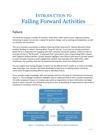
ISO Analysis (RTL)RedundantISO StrategyPDCOREVCORE (0.8)Missing ISOStrategyPDMEM1VMEM1 (OFF / 0.8)PDMEM2VMEM2 (OFF) Missing ISO Strategy– Isolation strategy is required on OFF- ON Paths Redundant ISO Strategy– No state where source is OFF and sink is ON46
LS Analysis (RTL)RedundantLS StrategyPDCOREVCORE (0.8)Missing LSStrategyPDMEM1VMEM1 (OFF / 0.8)PDAOVAO(1.2) Missing LS Strategy– Driver and receivers operate at different voltages Redundant LS Strategy– No state where there is a voltage difference47
Static Verification (RTL)PDMEM1(OFF)VCOREPDCORE Control signals driven from domain that could beshutdown when the receiving logic is ON– Driver supply of the control signals needs to be at least asON as the supply of the receiving logic48
ISO SupplyISO Supply OKPDMEM1VMEM1 (OFF)VCORE / VAOISO SupplyIncorrectPDMEM2VMEM2 (OFF)PDCOREVCORE(0.8)VMEM1 / VMEM2 Incorrect ISO supply– ISO supply needs to be at least as ON as the receiving logic49
ISO Control ConnectivityClamp ValuePDMEM1VMEM1 (OFF)Series of INVand/or BUFPDCOREVCORE(0.8)POWERMANAGER Verify ISO cell type, control connectivity and polarity– Compare ISO strategy in UPF to actual ISO cells in the netlist50
Always ON BufferingVMEM1VCOREVCOREPDMEM1VMEM1 R Buffering– Always ON buffers on feed-through paths need to use theproper supply51
Power Aware Simulation (RTL) Functional Simulation– Doesn’t take into account the Power related effects Power Aware Simulation– Simulates the effects due to Power related changes– Catch Control Sequence and Architectural bugsHDL (DUT)Libraries (.v,.sv, .vhd, .lib)Power awareTestbenchUPFWaveformPower AwareSimulatorReportsCoverage52
Power Aware Simulation (RTL)CtrlVMEM1XXXCtrlXPDCOREXPDMEM1 Simulation of Supply Network Shutdown Corruption– OFF domain propagates X values in simulation Virtual ISO insertion53
Power Aware TestbenchModeling off-chip suppliesPower AwareTestbenchVCOREVAOmodule testbench; initialbeginUPF::supply on(“VCORE”,0.8);UPF::supply on(“VAO”, 1.2); UPF::supply off(“VCORE”); end54
Retention Simulation (RTL)VDDVDDBVDDRRSAVERESTOREVDD VDDBVDDRR Partial Retention– Have you retained enough to get back to your original state?– Have you retained more than required?55
Power Aware Simulation (RTL)SAVEISO ENPWR ENVDDRESTORE ISO control– Enable before Power OFF and disable after Power ON Retention– Save & Restore signal sequencing56
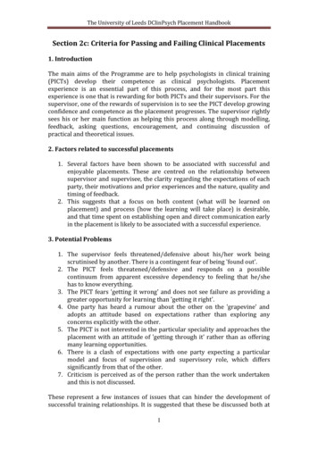
Power Switch ACKISO ENPWR ENVDDACKackdelayackdelay Power switch ACK signal– used to determine when the domain has been powered up– The domain can then be reset and isolation disabled Delay modeled using ack delay57
Power Aware Coverage Functional coverage– only addresses the design functionality without theeffects of Power Power Aware coverage– needs to address the aspects of Power Coverage of System Power States– Power states that a system is designed for need to becovered by the simulation vectors Coverage of Transitions– All legal transitions need to be covered– Negative tests to cover illegal transitions ensure thesystem doesn’t behave undeterministically58
Conclusion Most of todays SOCs have Low Power. Power Aware verification at all design stages (RTL,Implemented netlist and PG netlist) is a must toensure silicon success. Power Aware Static verification is required to catchbasic power related bugs quickly without having anytest scenarios. Power Aware simulation is required to catch controlsequence related bugs using power awaretestbench. Power Aware coverage ensures that all Powerrelated scenarios have been covered.59
What is UPF? An Evolving Standard -Accellera UPF in 2007 (1.0) -IEEE 1801-2009 UPF (2.0) -IEEE 1801-2013 UPF (2.1) -IEEE 1801A-2014 UPF (2.2) For Power Intent -To define power management -To minimize power consumption -Through control of leakage Based upon TCL -Tcl syntax and semantics -Can be mixed with non-UPF TCL