Transcription
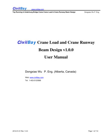
GMK6220All TerrainHydraulic Crane
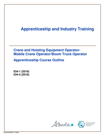
Dimensions28’6”(8700)”)6’570’ (42R1Ra 35R 3714R(10590)R 38’(11580)Ra 34’9”3’2”(960)(4995)(3360)(1068 R4Ra 3 ’ 7 ”R(138’6” 3280 R 38’8)(11”a3743’7 (1170)90”(6000)16’1”RR44Ra ’ 3 ” (135039’0)2”(12Ra 2’1017 ” ( ��(4230)(2800)3’(91713’1”(4000) 61/2” (170)-5” (130)5”11”17 18 ”4’11”1’ 10”(1500)(565)(3550)(400)49’7”(15105)Note: ( ) Reference dimensions in mmBASIC WEIGHTS (LBS.)Axles 1& 2Axles 3 - 6TotalWith Cummins Power, 20.5 R25 Tires39,172102,562141,734With Mercedes Power, 20.5 R25 Tires38,810102,218141,028Additions:Outrigger PadsAuxiliary HoistAdditional Hydraulic Oil CoolerBrackets & Hydraulic Reeling Drum for Lattice ExtensionLattice Extension - 43/72 ftSpare Tire - 14.00 R25Spare Tire - 16.00 R25Spare Tire - 20.5 R25Boom Removal 75,291584717809265Removal:Front Outrigger Beams & JacksRear Outrigger Beams & JacksBoom Assembly (minus lift cylinder)*Lift Cylinder*16.00 R25 Tires in lieu14.00 R25 Tires in s weights with superstructure facing forward2GMK6220
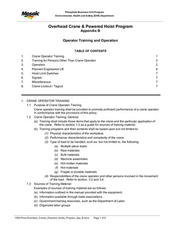
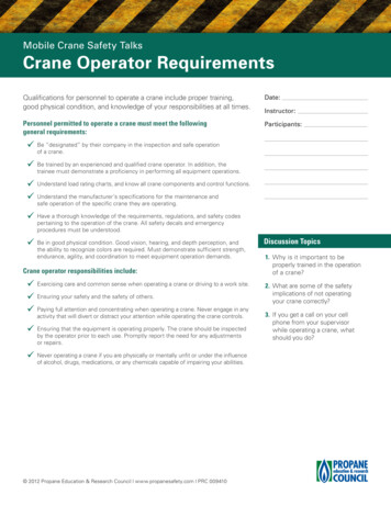
Working rangeBoom44 - 197 ft.(13.5 - 60 m)138,800 lbs.(63,000 kg)Outriggers RotationCounterweight100%360 FEET220210197 FT.200190180166 FT.170160150136 FT.140130120105 FT.1101009075 FT.8070605044 FT.4082 MAX.BOOMANGLE302010190 180 170 160 150 140 130 120 110 100 908070605040302010FEETAXIS OF ROTATION3GMK6220
Superstructure specificationsBoomFuel Tank Capacity44 ft. - 197 ft. (13.5 m - 60 m) six section, full-powerboom with patented “twin-lock” boom pinning system.Maximum tip height: 207 ft. (63 m).53 gal. (200 L).Boom ElevationSingle lift cylinder with safety valve provides boomangle from -1.5 to 82 .Lattice Extension43 ft. - 72 ft. (13 m - 22 m) lattice swingaway extension. Hydraulically offsettable 5 - 40 with hydraulicluffing.*Optional Lattice Jib ExtensionTwo 26 ft. (8 m) inserts for use with lattice swingawayextension to increase length up to 98 ft. (30 m) or125 ft. (38 m). Hydraulically offsettable 5 - 40 withhydraulic luffing.Load Moment & Anti-Two BlockSystemLoad moment and anti-two block system withaudio/visual warning and control lever lockout provides electronic display of boom angle, length, radius,tip height, relative load moment, maximum permissible load, load indication and warning of impendingtwo-block condition.CabAll aluminum construction cab is tiltable (approximately 20 ) and includes safety glass and adjustable operator’s seat with hydraulic suspension. Other featuresinclude engine dependent hot water heater, armrestintegrated crane controls, and ergonomically arrangedinstrumentation.Swing3 swing gears with axial piston fixed displacementmotors provide swing speed of 0 - 1.7 RPM thru planetary gear box. Also provided is a spring applied,hydraulically released automatic swing brake withfoot-operated release for free swing.Hydraulic system3 separate circuits, 2 axial piston variable displacement pumps, with electronic power limiting controland 1 axial piston variable displacement pump forswing. Standard thermostatically controlled oil coolerkeeps oil at optimum operating temperature.Tank capacity: 259 gal. (980 L)Control systemFull electronic control of all crane movements is accomplished using electrical control levers with automaticreset to zero. Controls are integrated with the LMI andengine management system by CAN-BUS.HoistMain and auxiliary hoist are powered by axial pistonvariable displacement motor with planetary gear andbrake. “Thumb-thumper” hoist drum rotation indicatoralerts operator of hoist movement.MainAuxiliaryLine length:984 ft.(300 m)755 ft.(230 m)Rope diameter:22 mm22 mmLine speed:426 ft./min.426 ft./min.Line pull:21,000 lbs.(93.4 kN)21,000 lbs.(93.4 kN)Electrical system24 V system with three-phase alternator 28 V/80 A,2 batteries 12 V/170 Ah.*Optional equipment*Engine-independent hot water heater, with enginepre-heater*Second spotlight*Stereo/cassette player*Air ConditioningCounterweight138,800 lbs. (63 000 kg) consisting of various sections with hydraulic installation/removal system (seecounterweight configuration on page 12).EngineCummins 6BTA5.9-C, diesel, 6 cylinders, watercooled, turbocharged, 165 HP (123 kW) at 2000 rpm.Max. torque: 538 ft. lbs. (730 Nm) at 1500 rpm.Engine emission: EUROMOT/EPA/CARB (off highway).* Denotes optional equipment4GMK6220
Carrier specificationsChassisTiresBox-type, torsion resistant frame is fabricated fromhigh-strength steel.12 tires, 20.5 R25.Outrigger SystemDual circuit steering system is hydraulic powerassisted with a transfer case mounted, ground driven,emergency steering pump. Axles 1, 2, 3, 5 and 6 steeron highway. Separate steering of the 4th, 5th and 6thaxle for all wheel steer and crab-steer is controlled byan electric rocker switch.Hydraulic two-stage outrigger beams are extended bya single hydraulic cylinder and two cables. Outriggerscan adjust to two positions:Fully extended (100%) - 27’ 11” (8.5 m)Partially extended (50%) - 19’ 8 “ (6 m)Four 29.5 in. x 32 in. (750 mm x 810 mm), selfstowing, steel outrigger pads provide rigid lifting base.Outrigger controls are located on both sides of thecarrier. An electronic level indicator is located next toeach outrigger control box.EngineCummins N14-525 E , diesel, 6 cylinders, watercooled, turbocharged, 525 HP (392 kW) at 2100 rpm.Max. torque: 1850 ft. lbs. (2509 Nm) at 1200 rpm.Engine emission: EUROMOT/EPA/CARB (onhighway).SteeringBrakesA dual circuit air system operates on all wheels with aspring-applied, air released parking brake acting onaxles 2, 4, 5 and 6. An air dryer is fitted to removemoisture from the air system.Auxiliary exhaust brake and constant throttle brake isstandard.Cab132 gal. (500 L).Two-man, aluminum construction driver’s cab includesthe following features: safety glass; driver andpassenger seats with hydraulic suspension, enginedependent hot water heater, complete instrumentationand driving controls.TransmissionElectrical systemAllison automatic CLT 755, 5 forward and 1 reversespeed. Transfer case with 2 speeds and inter-axledifferential lock.24 V system with three-phase alternator 28 V/80 A,2 batteries 12 V/170 Ah.Drive/Steer48 mph (77km/h) with 20.5 R25 tires.Fuel Tank capacity12 x 8 x 12.Axles6 axles. 1, 2, 4 and 5 are drive/steer. Axles 3 and 6are steer only.SuspensionGMK6220 features the Grove exclusive MEGATRAK†suspension. This revolutionary design features anindependent hydroneumatic system with hydrauliclockout acting on all wheels. The suspension can beraised 6-1/2” (170 mm) or lowered 5” (130 mm) bothlongitudinally and transversely and features anautomatic leveling system for on-highway travel.Maximum SpeedGradeability (theoretical)46% with 20.5 R25 tires.Miscellaneous standard equipmentBoom removal kit; trailing boom kit (less dolly); additionalhydraulic oil cooler; spare tire and wheel - 20.5 R25 withcarry bracket; flashing amber warning light on carriercab; working light; tool kit; fire extinguisher; roostersheave; radio cassette in carrier cab.* Optional equipment* Electric driveline retarder* 16.00 R25 tires (vehicle width 9 ft. 10 in. [3 m])* 14.00 R25 tires (vehicle width 9 ft. 9 in. [2.98 m])* Outrigger pressure measurement devices* Folding bunk bed in carrier cab* Engine-independent hot water heater, with enginepre-heater* Third seat* Trailing boom “boost” weight transfer kit* Air conditioning* Mercedes-Benz engines* Denotes optional equipment† “G MEGATRAK” (and design) is a trademark of Grove U.S. L.L.C.GMK62205
CounterweightBoom44 - 197 ft.(13.5 - 60.0 m)138,800 lbs.(63,000 kg)RotationOutriggers100%27’11” Spread360 Boom .076.068.061.056.050.046.043.0Pounds 0.49.809.208.60† 440,000 lbs is a Comparative Rating.Lifting capacities greater than 350,000 lbs require additional equipment.Note: Above char t also available with reduced outr iggers.CounterweightBoom44 - 197 ft.(13.5 - 60.0 m)94,700 lbs.(43,000 kg)RotationOutriggers100%27’11” Spread360 Boom .057.051.046.041.036.833.2Pounds 012.811.610.49.48.47.66.86.05.2† 440,000 lbs is a Comparative Rating.Lifting capacities greater than 350,000 lbs require additional equipment.Note: Above char t also available with reduced outr iggers.THIS CHART IS ONLY A GUIDE AND SHOULD NOT BE USED TO OPERATE THE CRANE. The individual crane's load chart, operating instructions and other instructional plates must be read and understood prior to operating the crane.6GMK6220
CounterweightBoom44 - 197 ft.(13.5 - 60.0 m)28,600 lbs.(13,000 kg)RotationOutriggers100%27’11” Spread360 Boom .631.426.823.220.017.415.2Pounds 219.817.014.612.410.68.87.46.04.83.6Lifting capacities greater than 350,000 lbs require additional equipment.Note: Above char t also available with reduced outr iggers.CounterweightBoom44 - 197 ft.(13.5 - 60.0 m)9,700 lbs.(4,200 kg)RotationOutriggers100%27’11” Spread360 Boom 10.08.20Pounds .613.410.88.66.85.03.6Lifting capacities greater than 350,000 lbs require additional equipment.Note: Above char t also available with reduced outr iggers.CounterweightBoom44 - 197 ft.(13.5 - 60.0 m)0 lbs.(0 kg)RotationOutriggers100%27’11” Spread360 Boom 9.039.231.826.021.618.015.012.410.28.26.44.8Pounds 19728.422.417.814.010.88.46.04.2Lifting capacities greater than 350,000 lbs require additional equipment.Note: Above char t also available with reduced outr iggers.THIS CHART IS ONLY A GUIDE AND SHOULD NOT BE USED TO OPERATE THE CRANE. The individual crane's load chart, operating instructions and other instructional plates must be read and understood prior to operating the crane.GMK62207
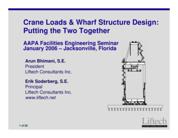
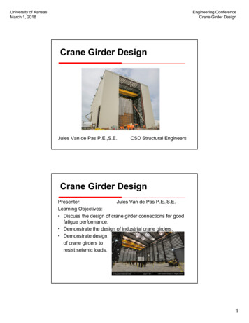
Working RangeOutriggers RotationCounterweightBoom121 - 197 ft.(36,8 - 60 m)43 - 125 ft.(13 - 38 m)138,800 lbs.(63,000 kg)100%360 FEET3405 20 32031040 T. 125 F330. 98 FT300290T. 72 F280270260250T. 43 F240230220210200182 FT.190166 FT.180170151 FT.160136 FT.150140121 FT.130197 FT.12011010090807060504082 MAX.BOOMANGLE302010250 240 230 220 210 200 190 180 170 160 150 140 130 120 110 100 90 80 70 60 50 40 30 20 10FEETAXIS OF ROTATION8GMK6220
CounterweightBoom197 ft.(60.0 m)43-72-98-125 ft.(13-22-30-38 m)138,800 lbs.(63,000 kg)RotationOutriggers100%27’11” Spread360 Pounds 901952002052102152202252302352402455 48.07.47.06.66.05.65.24.84.44.0Boom197 ft.(60.0 m)43 FT20 .86.25.85.45.0Luffing Jib43-72-98-125 ft.(13-22-30-38 m)40 72 FT20 5 00 lbs.(63,000 kg)40 72 FT5 - 20 20 - 40 6.46.26.05.65.24.8125 FT20 5 .82.62.440 4.64.44.24.03.83.63.43.2360 Luffing Jib43 FT5 - 20 20 - 40 9.48.68.88.08.47.67.87.06.66.25.65.24.84.440 .48.07.67.27.06.4100%27’11” Spread98 FT20 5 67.47.06.66.25.8Pounds (thousands)5 - 20 66.26.05.85.65.25.04.64.44.03.63.43.02.82.42.298 FT20 - 40 26.05.85.65.45.04.84.4125 FT5 - 20 20 - 40 4.24.03.83.63.43.23.22.8THIS CHART IS ONLY A GUIDE AND SHOULD NOT BE USED TO OPERATE THE CRANE. The individual crane's load chart, operating instructions and other instructional plates must be read and understood prior to operating the crane.GMK62209
CounterweightBoom197 ft.(60.0 m)43-72-98-125 ft.(13-22-30-38 m)94,700 lbs.(43,000 kg)RotationOutriggers100%27’11” Spread360 Pounds 901952002052102152202252305 66.86.05.24.43.83.22.6Boom197 ft.(60.0 m)43 FT20 .84.03.42.8Luffing Jib43-72-98-125 ft.(13-22-30-38 m)40 72 FT20 5 .02.4Counterweight94,700 lbs.(43,000 kg)40 72 FT5 - 20 20 - 40 .68.48.27.66.86.25.64.84.43.83.22.82.25 4.84.64.23.63.02.6125 FT20 40 4.03.42.82.2360 Luffing Jib43 FT5 - 20 20 - 40 .05.85.04.43.83.22.62.240 � Spread98 FT20 5 67.06.45.65.04.4Pounds (thousands)5 - 20 66.26.05.65.04.43.83.42.82.498 FT20 - 40 26.05.85.24.64.03.43.0125 FT5 - 20 20 - 40 THIS CHART IS ONLY A GUIDE AND SHOULD NOT BE USED TO OPERATE THE CRANE. The individual crane's load chart, operating instructions and other instructional plates must be read and understood prior to operating the crane.10GMK6220
29’6”Boom extension configurations–40 1’8”(0.5 m)26’(8 m)26’(8 m)6’7”(2 m)(1 340. ’55 ”m)5 Length (ft.)GMK6220Intermediate section boom extension make-up26’(8 m)6’7”(2 m)34’5”(10.5 m)29’6”(9 m)43—1x1x—72—1x1x1x981x1x1x1x1252x1x1x1x11
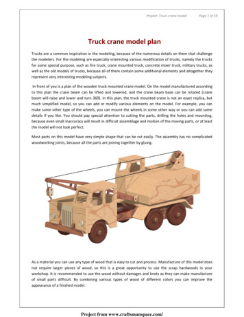
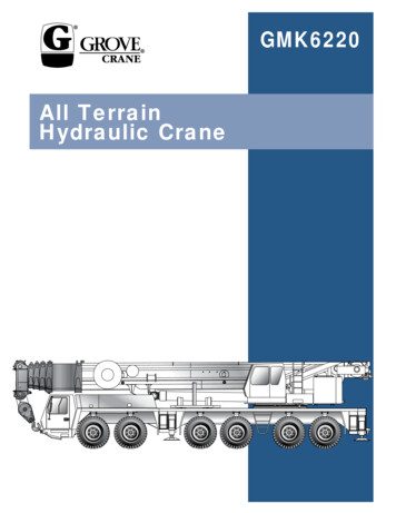
Counterweight 0)6543781 29,700 lbs. (4,400 kg)2.11,200 lbs. (5,100 kg)3.18,700 lbs. (8,500 kg)4.24,300 lbs. (11,000 kg)5.23,100 lbs. (10,500 kg)6.7,700 lbs. (3,500 kg)7.22,050 lbs. (10,000 kg)R 16’5”(4995)R 0 lbs. (10,000 ��9”(2980)Note: ( ) Reference dimensions in mm112234569,700 lbsX20,900 lbs.XX28,600 lbs.XX47,300 lbs.XXX71,600 lbs.XXXX94,700 lbs.XXXXXX138,800 lbs.XXXXXX78XXXXXGMK6220
Rated Lifting CapacitiesIMPORTANT NOTES:WARNING: THIS CHART IS ONLY A GUIDE.The notes below are for illustration only andshould not be relied upon to operate the crane.The individual crane's load chart, operatinginstructions and other instruction plates mustbe read and understood prior to operatingthe crane.1. All rated loads up to 420,000 pounds meetANSI/ASME B30.5, Mobile and Locomotive Cranes.Testing and development were performed toSAEJ1063, Cantilevered Boom Crane Structures Method of Test and SAEJ765 Crane Stability TestCode.2. Capacities given do not include the weight ofhook blocks, slings, auxiliary lifting equipment andload handling devices. Their weights must be addedto the load to be lifted. When more than minimumrequired reeving is used, the additional rope weightshall be considered part of the load.3. The machine shall be leveled on a firm supportingsurface. Depending on the nature of the supportingsurface, it may be necessary to have structural supports under the outrigger floats to spread the load toa larger bearing surface.4. When either boom length or radius or both arebetween values listed, the smallest load shown ateither the next larger radius or next longer or shorterboom length shall be used.5. For outrigger operation, outriggers shall be properly extended with tires raised off the ground beforeoperating the boom or lifting loads.Symbols er ControlsAxlesEngineBrakesFuel Tank CapacityTiresElectrical SystemSuspensionDriveRotationLightsBoom ElevationCabSwingBoomCounterweightFixed SwingawayOilTele-SwingawayHydraulic SystemLattice Extension(Luffing)HoistBoom NoseRadiusBoom ExtensionBoom Length† Comparative RatingA rating designation based upon the premise thatlarge capacity European cranes are typically purchased and used as long boom, high reach, longradius lift cranes not as heavy lift cranes.To provide a GMK 6220 crane with the necessaryequipment to achieve maximum lift capacity willdrastically reduce long boom performance.Therefore, augmenting lifting equipment is requiredfor buyers who require such capacities.SpeedHHookblockGradeGearLattice ExtensionLuffing JibGMK6220
Grove Worldwide – World Headquarters1565 Buchanan Trail EastP.O. Box 21Shady Grove, Pennsylvania 17256, U.S.A.Tel: [Int 1] (717) 597-8121Fax: [Int 1] (717) 597-4062Western Hemisphere, Asia/PacificGrove Europe Limited*Sunderland SR4 6TT, EnglandTel: [Int 44] 191 565-6281Fax: [Int 44] 191 564-0442Europe, Africa, Middle EastGrove China - Representative OfficeBeijing Hotel Room 6074No. 33 East Chang An AvenueBeijing, 100004, ChinaTel: [Int 86] (10) 513-7766Fax: [Int 86] (10) 513-7307Grove Middle EastP.O. Box 290Dubai, United Arab EmiratesTel: (Int 971) (4) 378400Fax:(Int 971) (4) 373660Deutsche Grove GmbHSales and ServiceHelmholtzstrasse 12, Postfach 5026D-40750 Langenfeld, GermanyTel: [Int 49] (2173) 8909-0Fax: [Int 49] (2173) 8909-30Lifetime Customer SupportWestern Hemisphere, Asia/Pacific1086 Wayne AvenueChambersburg, Pennsylvania USATel: [Int 1] (717) 263-5100Fax: [Int 1] (717) 267-0404Wilhelmshaven WorksIndustriegelande West, Postfach 1853D-26358 Wilhelmshaven, GermanyTel: [Int 49] (4421) 294-0Fax: [Int 49] (4421) 294-301Europe, Africa, Middle EastSunderland SR4 6TT, EnglandTel: [Int 44] 191 565-6281Parts Fax: [Int 44] 191 510-9242Service Fax: [Int 44] 191 510-9560Grove Asia/Pacific - Regional Office171 Chin Swee Road#10-09 San CentreSingapore 0316Tel: [Int 65] 536-6112Fax: [Int 65] 536-6119Asia/Pacific, Near Easthttp://www.groveworldwide.com*Grove Europe Limited, Registered in England,Number 1845128, Registered office, Crown Works,Pallion, Sunderland, Tyne & Wear, England SR4 6TTConstant improvement and engineering progress make it necessary that wereserve the right to make specification, equipment, and price changes withoutnotice. Illustrations shown may include optional equipment and accessories andmay not include all standard equipment.Distributed By:Form No.: GMK6220Part No.: 3-1310 699-10MPrinted in U.S.A.
integrated crane controls, and ergonomically arranged instrumentation. Swing 3 swing gears with axial piston fixed displacement motors provide swing speed of 0 - 1.7 RPM thru plan-etary gear box. Also provided is a spring applied, hydraulically released automatic swing brake with foot-operated release for free swing. Counterweight