Transcription
White Paper: XIlinx FPGAsWP401 (v1.0.1) March 7, 2012DO-254 for the FPGA DesignerBy: Dagan WhiteThe standard that governs the design of avioniccomponents and systems, DO-254, is one of the mostpoorly understood but widely applicable standardsin the avionic industry. While information on thegeneral aspects of the standard is easy to obtain, thedetails of exactly how to implement the standard aresketchy. And once an entity develops a process thatachieves compliance, the details of how compliancewas achieved become part of the intellectualproperty of that entity. This white paper focuses onthe details of developing a DO-254 compliantprocess for the design of FPGAs. Copyright 2011–2012 Xilinx, Inc. XILINX, the Xilinx logo, Virtex, Spartan, ISE, and other designated brands included herein are trademarks of Xilinx in the United States andother countries. All other trademarks are the property of their respective owners.WP401 (v1.0.1) March 7, 2012www.xilinx.com1
DO-254 - The GeneralDO-254 - The GeneralDO-254, Design Assurance Guidance for Airborne Electronic Hardware [Ref 1], providesguidance for design assurance in airborne electronic hardware (AEH) to ensure safeoperation. Rather than specify how to implement the standard or which test should becompleted, it specifies the requirements for a process of design assurance andcertification. It is the lack of specifics that causes uncertainty with the user communityon how to develop a design assurance process that meets DO-254.Per the standard, all flight hardware needs to be classified according to a designassurance level (DAL). The standard defines five levels regarding the safety andcriticality of an avionic system (A to E). For example, engineers designing to level A orB face a much more rigorous test, verification, and documentation process than forlevels C, D or E [Ref 2].Central to DO-254 is the hardware life cycle, describing the general phases a projectmoves through, from initial planning to certification, including feedback loops toallow adaptation of requirements as necessary. Similar to other quality standards,DO-254 does not specify how to manage the life cycle nor the tools and methods to beused. However, it does require that design and certification procedures, methods, andtools be documented, along with the criteria used to determine when a project isallowed to move to the next phase.Key to DO-254 is the designated engineering representative (DER) [Ref 3]. The DER isan appointed engineering resource who has the authority to pass judgment onaviation-related design and development, acting as the certification authority onbehalf of the civilian aviation authorities. The standard allows the DER to be either anemployee of the system developer or an independent consultant. Given that the DERmust be approved by the civilian aviation authorities, the DER is often a consultanthired by the system developer. The DER has the authority to certify the process andcan therefore assist in defining the process and the associated hardware life cycle.A DER's involvement in a project depends upon the type and scope of a developmentproject. Some example scenarios are: Self certify and submit without a DER: Very rare and only possible with systemdevelopers with extensive knowledge of DO-254 and aviation authority policyand a long history of safety.Internal DER: Common in larger avionics companies with sufficient activity tojustify the expenses.Consultant DER: Common for line-replaceable-unit (LRU), board, or IPdevelopers, or for companies whose main business is not avionics.DER as an auditor: A DER only audits the development on behalf of an aircraftintegrator. This scenario can apply to board and IP developers where the endcustomer takes responsibility for managing the certification process.DO-254 Hardware Life CycleDO-254 segregates the various activities of the hardware life cycle for complexelectronic hardware (CEH) into one of three processes: planning, development, andcorrectness. In parallel to these three processes is the verification and validationprocess. Along with these three high-level processes, the standard also specifies whattype of documentation must be kept (and delivered) to both manage and documentthe hardware life cycle. Again, DO-254 does not specify how each of these processes2www.xilinx.comWP401 (v1.0.1) March 7, 2012
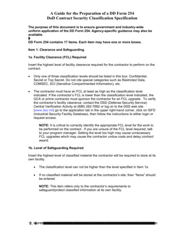
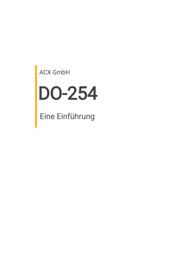
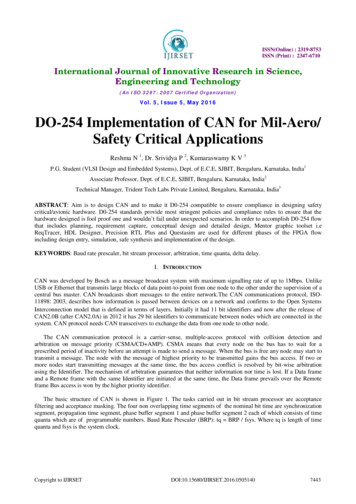
DO-254 Hardware Life Cycleshould be completed, but rather how each should be documented for review by thecertification authorities.Figure 1 shows the DO-254 hardware life cycle with the included hardware designprocess (section numbers shown refer to the applicable section of the standard). Thevarious parts of the FPGA design process are shown, mapped to the hardware lifecycle. In addition, processes that feed into and out of the hardware life cycle areshown.X-Ref Target - Figure 1Planning(Section 4) Define Hardware Life Cycle Set Program Milestones Define Transition Requirements Set Development andVerification EnvironmentHardware Design ProcessRequirements CaptureHardware Safety Assessment(Section 5.1)(Section 2.3) Detailed Design Specification Block Diagrams State Machine Design Testbench Development Set Design Assurance Level Set Acceptable FIT Levels Determine Needs for Redundancy Specify SEU Mitigation StrategyConceptual Design(Section 5.2) Behavioral DesignSupporting ProcessesVerification and ValidationDerived Requirements(Section 6)Detailed Design(Section 5.3) Synthesis Place and Route Bitstream Generation Behavioral and Gate-LevelSimulation Timing Analysis Verification Test Test Coverage Analysis Design Review Specify SEU Mitigation StrategyImplementationConfiguration Management(Section 5.4)(Section 7) Prototype Development Test and DebugProcess AssuranceProduction Transition(Section 8)(Section 5.5) Manufacturing Test DevelopmentCertification Liaison(Section 9)Acceptance Test(Section 5.6)Hardware Life CycleSeries Production(Section 5.7)WP401 01 072611Figure 1:WP401 (v1.0.1) March 7, 2012DO-254 Hardware Life Cycle for Complex Electronic Hardwarewww.xilinx.com3
PlanningPlanningA plan for achieving DO-254 certification must be developed and documented forreview by the DER. This plan, referred to as the plan for hardware aspects ofcertification (PHAC), summarizes the system's functionality, its architecture, thehardware and validation process, and for levels A to C, verifies fail-safe operation ofthe system using different redundancy strategies. The PHAC also must include detailsregarding the development environment, system testing, the different phases ofsystem hardware development, and the transition criterion. In addition, themechanism for incorporating derived requirements (in other words, detailedrequirements stemming from work in later phases) must be covered.Along with the PHAC, a top-level drawing identifying all assemblies, subassemblies,and components must be delivered. For FPGA development, this includes a blockdiagram showing each functional partition and the I/O between functions, includinga description of each.After the PHAC is approved by the DER, development, testing, and implementationof the system can begin.Hardware Safety AssessmentWhile not considered a part of the hardware life cycle by DO-254, the hardware safetyassessment does directly impact FPGA design. This assessment determines the DALfor each functional block in the system. A system developer has the option of setting asingle design assurance level and strategy for an entire hardware item, or a hardwareitem can be determined to have separate functional failure paths (FFPs)—and as aresult, a separate DAL and assurance strategy.FPGAs, similar to SRAMs, possess a unique FFP—susceptibility to single-event upsets(SEUs). When high-energy particles (primarily neutrons) pass through the siliconsubstrate of a device, charged particles are created as the result of collisions. If thecharge of these particles is sufficient, they can change the state of a static memoryelement. These changes of state are referred to as SEUs. With an SRAM FPGA, not onlydo SEUs occur in the device memory but in the configuration memory as well,potentially creating a change in the FPGA's programmed logic.Because of the increased neutron flux at high altitude (the flux at 40,000 feet can beroughly 600 times that of a ground-based observe), the potential of configurationupsets must be included in any assessment. Moreover, mitigation strategy must beselected based upon the predicted FIT(1) rate as well as the required DAL. For moredetails on the impact of SEUs in avionics and various mitigation techniques, see theXilinx Avionics Developers’ website [Ref 4].The output of this stage is a system safety assessment (SSA) detailing the DAL for theitem, the assurance strategy to be pursued, and the recommended SEU mitigationstrategy.1. To assist customers in predicting FIT rates prior to mitigation for selected Xilinx FPGAs, Xilinx has developed anSEU FIT rate calculator. Requests for the FIT rate calculator can be sent to avionics@xilinx.com.4www.xilinx.comWP401 (v1.0.1) March 7, 2012
Hardware Design ProcessHardware Design ProcessThe hardware design process phase is broken into five distinct sub-processes thatmust be documented: Requirements capture: The architecture of the system (and the system-levelrequirements), including items such as test structures and interfaces, needs to bedescribed and documented. During this phase, the design team must develop ablock-level description of the system, including block diagrams, state diagrams,and flow charts, that are consistent with the requirements.Conceptual design: During this phase, hardware design can begin with HDLdevelopment. The output of these activities plus the results of preliminary designreview are submitted to the DER for review. Simulation, while part of verification and validation, is considered a naturalpart of the conceptual and detailed design processes.Detailed design: During this phase, the design is synthesized, andplace-and-route is completed. After the confidence in the design is high,bitstreams are generated.Implementation: During this phase, FPGAs are programmed and prototypes aredeveloped to allow test and debug.Production transition: In the last phase, the FPGA/board is prepared for release tomanufacturing. After the board and FPGA are fully debugged, test engineeringcompletes production and reliability testing, a baseline is established to ensureconsistent system production, acceptance testing is defined.Supporting ProcessesRunning concurrently with the development processes, the supporting processes aredesigned to manage certification activities and ensure that the top-level requirementshave been implemented in hardware as intended.This collection consists of four majorprocesses: WP401 (v1.0.1) March 7, 2012Validation and verification: Validation assures that derived requirements(especially those relating to safety) are correct and complete with respect tosystem requirements. Verification assures that the hardware implementationmeets all of the hardware requirements, including derived requirements.Verification activities typically involve simulation at all levels (behavioral,structural, back-annotated timing), static timing analysis, fault simulation, testcoverage analysis, and design reviews.Configuration management: This process archives all data needed for certificationand all data needed to return production to any earlier version.Process assurance: This activity ensures that hardware life cycle data andprocesses comply with the planning documents.Certification liaison: This process defines the communication between the systemdeveloper and the certification authority (usually, the DER), covering how data isapproved, joint reviews, and when and how the certifying authority witnessescompliance testing.www.xilinx.com5
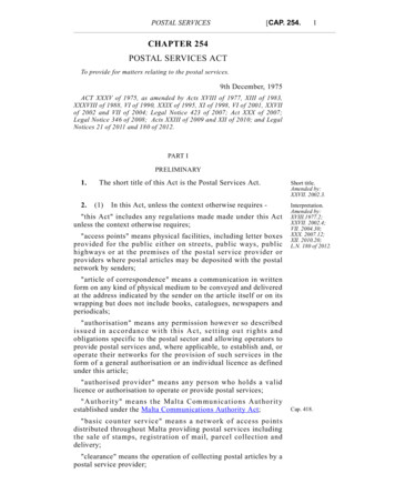
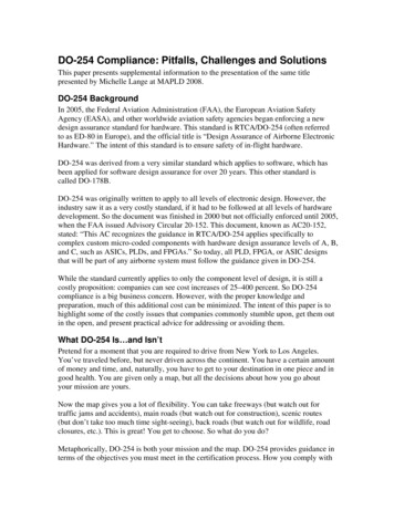
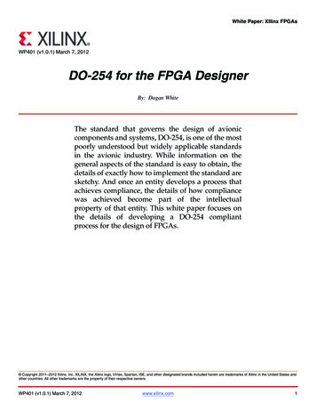
Documentation and OrganizationDocumentation and OrganizationNo standard is complete without a requirement for documentation. The DO-254standard refers to artifacts, which are documents, reports, results, standards, or designfiles that are developed or generated as part of the development process. While thestandard does not specifically set what data items are needed, it does provide generalguidelines for the type of documents, reports, and data needed and in what context.Ultimately, the DER reviews the artifacts as part of the certification process. Havingthe artifacts properly controlled and linked streamlines this process.The development organizational structure is the responsibility of the systemdeveloper. While it might be inferred that the standard requires parts of the designprocess be handled by different organizations, that is not the case.Figure 2 provides a detailed breakdown of the type of documents needed as inputsand outputs for each phase of the FPGA design process, plus an indication of whatorganization function is involved in a particular phase. The production phase isshown for completeness but not described in this white paper.X-Ref Target - Figure 2Development PhasePlanning PhaseProduction esVVSHDSHDRD (CCD)RTL UALDESIGNDETAILEDDESIGNHRTestbenchesReview RecordsProcess RecordsHDRD (CCD)RTL CodeTestbenchesFFPAReview RecordsProcess RecordsHDRD (DDD)RTL CodeTestbenchesBitstreamReview RecordsProcess SReview RecordsProcess RecordsProcessTransitionReviewPlanningReviewRTL CodeTestbenchesBitstreamHValPHVerPVVSHDRD (DDD)BitstreamPHACHCSHDRD (DDD)VVDHATCHDRD (DDD)BitstreamHDRD CTIONHDRD (DDD)VVDRTL CodeTestbenchesBitstreamReview RecordsProcess RecordsHASHATCHDRD (DDD)BitstreamReview RecordsProcess RecordsVVDReview RecordsProcess RecordsReview RecordsProcess RecordsReadinessR
DO-254 does not specify how to manage the life cycle nor the tools and methods to be used. However, it does require that design and certification procedures