Transcription
ACCELERATING DO-254 VERIFICATION
ACCELERATING DO-254 VERIFICATIONINTRODUCTIONAutomated electronic control systems or avionics allow lighter, more efficient aircraft to operate moreeffectively in the current and future airspace. Today’s modern aircraft use an increasing number ofmicrocomputers, microprocessors, and dedicated hardware to process growing amounts of data neededto control and monitor the status of the flight and related systems. In April of 2000, a joint RTCA SpecialCommittee and EUROCAE working group released the Design Assurance Guidance for AirborneElectronic Hardware. In 2005 the FAA formally recognized RTCA DO-254 as a means of compliance forthe design of complex electronic hardware in airborne systems with a goal to establish clear objectivesto ensure development of safe and robust avionics equipment.The guidance is intended to be applied across line replaceable units, circuit card assemblies andintegrated circuits, with the goal of ensuring that custom components, such as an ASIC or FPGA, meetintended functional and safety standards for airborne applications. The DO-254 specification utilizes arequirements-based design and verification approach. This means that the entire hardware projectrevolves around a formal set of high-level requirements. Prior to writing RTL, each of theserequirements must be captured, given a unique reference name, and reviewed for a variety of criteriaincluding understandability, testability and verifiability.The standard defines the hardware design processes and breaks it into these phases: Requirements Capture Conceptual Design Detailed Design Implementation Verification Transfer to productionThe more complex an ASIC or FPGA becomes, the more complex and sophisticated the tools supportingits development and verification must be. Verification is intended to check that a system, or a portionthereof, meets a set of design specifications. Verification of a hardware design can find errors at avariety of levels. Errors can be identified in the hardware requirements, translation of the design intoregister transfer language (RTL), or implementation of the RTL in hardware. To be able to certify thefunctionality of a system with design assurance level A or B, there are several different analyses thatmust be performed for complex systems. All of these analyses are iterative and must be reevaluatedwhenever a design change is made.
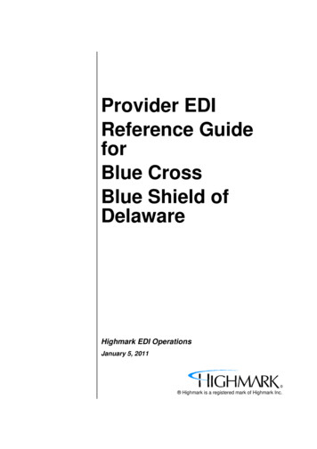
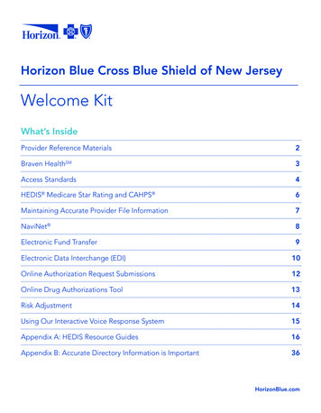
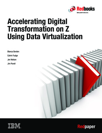
TYPICAL HARDWARE DESIGN FLOWThe typical hardware design and verification flow is illustrated below, with verification today taking 50%to 70% of the overall development time. By applying static, dynamic and formal verification practicesproven to reduce develop time, design iterations are reduced and design quality is increased.Figure 1 – Typical DO-254 Hardware Design FlowRTL VERIFICATIONRTL checking is an integral part of ASIC/FPGA design team workflows. DO-254 suggests that codingstandards should be defined and reviewed. However, the policy does not clarify what these standardsare and certification authorities usually do not have a good set of industry standard rules torecommend. Design teams or individual designers are then left to define a set of rules for RTL thatensures code quality. For example, when manually inspecting code, design teams may check forcommon coding errors, such as incomplete FSMs, latch inferencing, and incomplete sensitivity lists(which can cause mismatches between simulation and synthesis results). However, manual checking canbe error prone and result in issues being found late in the design flow.RTL coding practices can also affect timing closure. Long If-Then-Else structures or modules withunregistered ports, for example, will pass through simulation and synthesis without errors only toproduce long paths in the design. It can take days to identify the root cause looking through static timingresults.Modern ASIC or FPGA designs also usually contains many IP cores developed by multiple teams eitherinternal or external. Establishing and applying unified design rules for coding style is key for accuratesimulation and synthesis, and it improves the readability and maintainability of RTL. The quality of the IPfor complex systems is critical during integration. Leveraging a good lint tool can ensure correct-byconstruction design practices
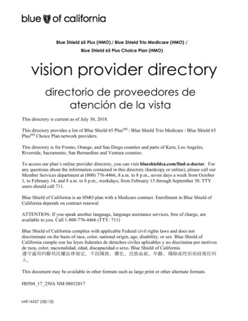
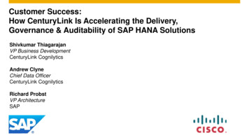
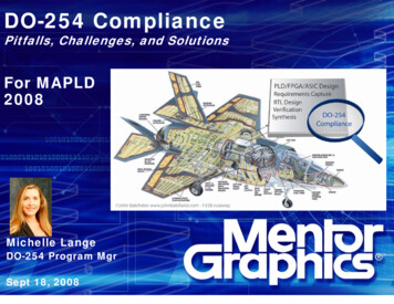
Recommend RTL checks include: Avoiding FSM state unreachability, terminal states, and coding issuesAvoiding differences between simulation and synthesis semanticsAvoiding operations with expensive implementation costsFollowing naming and RTL coding conventionsEnforcing RTL modeling clarity and reducing complexityEnforcing checks for clock bundles (clocks, enables, resets) and control signalsEnabling testability and traceability of the codeAvoid long ITE chainsConfirm all IP ports are registeredCROSS DOMIAN CLOCKING ISSUESSimulation requires the generation of appropriate test vectors and is an accepted traditional method forfunctional verification during the design creation phase, however it may not catch all design issues.Verification of the hardware using simulation may consist of both directed test vectors and randomlygenerated vectors. This method is entirely adequate to verify that the design specified in RTL performsthe intended function within the limits of simulation. However, simulation alone can miss critical issuesthat can cause metastability issues late in the system integration or, worse, after the system has beendeployed. While it is possible to find a CDC and then create a test vector, finding CDC issues usingsimulation is virtually impossibleIdeally, a design will have only a single master clock. Unfortunately, modern designs commonly requireseveral independent clocks used within a single system. When signals move from one clock domain toanother, special circuits and analyses are required.Figure 2 – Clock Domain Crossing without SynchronizerModern Clock Domain Crossing tools point out where synchronizers are required to allow signals tocross clock domain boundaries. Correct operation of circuits crossing clock domain boundaries cannot
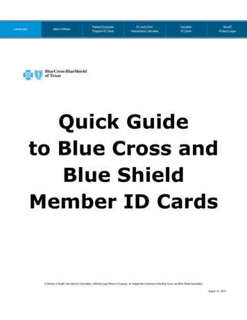
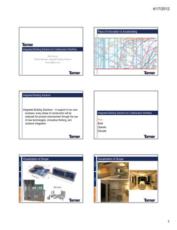
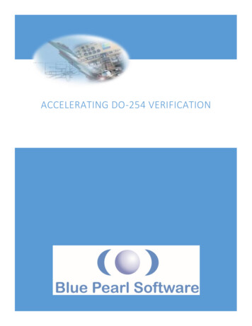
be guaranteed by simulation because the timing between different clock domains can vary arbitrarily.This would require an infinite number of simulations to verify.TYPICAL HARDWARE DESIGN FLOW LEVERAGING VISUAL VERIFICATION SUITEThe key to design assurance using DO-254 is identifying all possible design errors. Before a design errorcan be identified, a test case that produces the error must be generated, and then the error mustmanifest itself in a way that the test system can detect. Blue Pearl’s Visual Verification Suite’s (VVS)Analyze RTL incorporates a suite of technologies into a single RTL analysis environment to helpdevelopers find bugs earlier in the design processes. Super-lint tools are combined with the power offormal verification to provide a single, high capacity design checking environment that identifies poorcoding styles, improper clocks, simulation and synthesis problems, poor testability and other sourcecode issues. FSM analysis automatically extracts and analyzes finite state machines for dead or terminalstates and provides a visual representation. X-propagation analysis detects unknown states, oftenintroduced into designs to implement soft resets or to implement power management schemes that aremasked during RTL simulation.The VVS Advanced Clock Environment (ACE) and CDC Analysis provide graphical representationssummarizing data paths between clocks, and can make recommendations for grouping of clocks intoclock domains. With ACE, designers can identify clocks to better understand how they interact withsynchronizers in the design. This allows users to quickly identify missing synchronizers or improper clockdomain groupings. The VVS CDC Analysis incorporates over a decade of experience to find errors othertools may fail to identify.Figure 3 –DO-254 Hardware Design Flow Leveraging VVS
INDUSTRY’S ONLY STATIC VERIFICATION TOOL OPTIMIZED FOR FPGA AND ASICThe Visual Verification Suite offers the only Linting and CDC verification environment optimized for bothASIC and the unique requirements of FPGA design. Specific for FPGA are checks to analyze for routingcongestion, reset configurations and even estimate critical timing paths prior to synthesis. Grey Cellmodeling supports the analysis of FPGA vendor and 3rd party provided protected IP cores withasynchronous clock domains. The Visual Verification Suite supports Xilinx Vivado Design Suite withbuilt in UltraFast Design Methodology design rules, Microsemi Libero Design Suite and Intel Quartus Prime Design Software and is the only static verification environment that runs on Windows – thepreferred FPGA environment – as well as Linux operating systems.For more information about Grey Cell Modeling see RTL Analysis for Complex FPGA designs usinga Grey Cell Methodology to Improve QoRQUALIFYING BLUE PEARL SOFTWARE FOR DO-254Tool vendors do not qualify their own tools under DO-254. If you intend to use the Visual VerificationSuite on a DO-254 project, here are some suggestions for getting through audits.1) Do not qualify. If your project requirements do not call out the need for VVS, then it does notneed to be identified and described in the “Plan for Hardware Aspects of Certification” (PHAC)or other DO-254 documents. Unless you have a specific requirement for linting and orverification of CDCs, you can just leverage VVS without it becoming part of the DO-254 reviewprocess.2) If there is a specific requirement from your customer (or even your DER) that says you must uselinting or CDC tools then you must choose a method of tool assessment. The simplest one by faris Independent Output Assessment. In this case, you would specify something similar to thefollowing:“The results of the VVS are checked independently by thorough testing with 1000’s of independent testsusing both false positive and false negative testing. We have/will be conducting tests in hardware underreal system clocking frequencies and checked that all the conditions that were analyzed operate asexpected.”For more information on Blue Pearl’s Software’s reliability testing see: How Can We Build MoreReliable EDA Software Whitepaper
BLUE PEARL SOFTWAREBlue Pearl Software, Inc. is a provider of design automation software for ASIC, FPGA and IP RTLverification. Its Analyze RTL linting and debug, Clock Domain Crossing analysis and Synopsys DesignConstraints (SDC) generation solutions are proven to improve quality-of-results (QoR), reduce risk anddecrease development time. The Visual Verification Environment complements RTL simulation solutionsprovided by EDA and FPGA vendors by ensuring code and SDC quality along with clocking integrity.Engineered to maximize RTL find/fix rates, the Visual Verification Suite uniquely provides easy setup,consistent results, Management Dashboard for complete push-button analytics, and runs on both Linuxand Windows.
VISUAL VERIFICATION SUITE DO-254 PACKAGEPACKAGE: DO-254Description: This package includes checks that aid in compliance with the DO-254 military standard.Checks: GRST (Gated reset)HCCC (Do not hard-code constants)REGO (Register all module outputs)UNREACHABLE STATE (Report Unreachable states)MCD (No case default)MDA (Missing case default assignment)CSL (Complete sensitivity lists)MEB (Missing else block)LEC (Little endian checks)CCLP (Infinite and 0-count loops)SLCC (Separate lines for commands)INT TRI (Internal tristate objects)COMMENT END STMNTS (Comment end statements)MCA (Missing case item assignment)MIA (Missing if assignment)COMMENT NET DEC (Comment net declarations)NS NAME (Next state names)COMMENT PORT DEC (Comment port declarations)RST (All flip-flops resettable)RESET POLARITY (Check reset polarity consistency)FOREIGN LANGUAGE KWD (Report usage of Foreign Language keywords as identifiers)CLPR (No combinational loops)MULT MODS (Multiple modules in the same file)FILE HEADER (Use a file header)CONSTRUCT HEADER (Use a construct header)TERM STATE (Report Terminal states)MEA (Missing else assignment)NO TABS (Do not use tabs)IODECL (Mixed input/output/inout port declarations)POSEDGE (Use positive edge clocks)IGRST (Internally generated resets from different modules)IDDC (Isolate 'define' directives)VHDL CHECKS (Report VHDL naming rule violations)
Suite on a DO-254 project, here are some suggestions for getting through audits. 1) Do not qualify. If your project requirements do not call out the need for VVS, then it does not need to be identified and described in the “Plan for Hardware Aspects of ertification” (PHA) or other DO-254 documents. Unless you have a specific requirement for linting and or verification of CDCs, you can just .