Transcription
www.versa-lok.comStandardDesign & Installation Guidelines
WelcomeWelcome tothe VERSA-LOKStandardRetaining WallSystem Designand InstallationGuidelines.This guide is intended to illustrate design andVERSA-LOK offers a variety of technical support,construction capabilities of the VERSA-LOKincluding in-house engineering assistance and Standard Retaining Wall System. There arereference literature. Please call 800-770-4525many variables to consider, however, whenwith questions or to request the following:planning or constructing any segmental retainingYou also can download Technical Bulletins,wall. Soil types, drainage, loading, topographyproduct specifications and details from theand height need to be addressed on every projectVERSA-LOK website at www.versa-lok.com.to ensure safe, trouble-free installation.Walls which support heavy loads or exceed 4feet in height require special soil reinforcementand often professionally designed plans.Consult a qualified engineer if you are unsureabout any construction, site or soil conditions. Technical Bulletin #1Shoreline, Waterway and Retention Pond Protection Technical Bulletin #2Stairs Technical Bulletin #3Curves and Corners Technical Bulletin #4Caps Technical Bulletin #5Base Installation Technical Bulletin #6Freestanding Walls, Columns and Vertical Walls Technical Bulletin #7Tiered Walls Technical Bulletin #8Fences, Railings and Traffic BarriersAlso available from VERSA-LOK: Design and Installation Guidelines- VERSA-LOK Mosaic Technical Documentation forVersa-Grid Soil Reinforcement VERSA-LOK Standard and MosaicConstruction Details CD-Romcontaining specificationsand drawings created withAutoCAD softwareAutoCad is a registered trademark of Autodesk, Inc.1versa-lok standard design and installation guidelines
Table of Contents1 Introduction & Unit Specifications32 System Overview53 Wall Components Typical Section Foundation Embedment Soils and Compaction Drainage Within Walls Surface Drainage Geosynthetic Reinforcement64 Engineering115 Special Design Considerations Shorelines Loads Behind Walls Slopes Tiering136 Planning, Estimating & Final Designs157 Wall Construction Tools Unit Modification Excavation Leveling Pad Base Course Additional Courses Drainage Materials Compacted Soil Backfill Geosynthetic Soil Reinforcement Caps16This guidedemonstrates theexceptional designcapabilities andeasy installationmethods of theVERSA-LOKStandard RetainingWall System.258 Basic Wall Design Elements Curves Corners Stepped Base Stepped Wall Top Returns299 Advanced Wall Features Stairs Freestanding Walls Columns Guardrails, Railings and Traffic BarriersSUPPLEMENTAL INFORMATIONMaterial Estimation WorksheetVERSA-Grid Estimation ChartsVERSA-LOK Standard SpecificationsVERSA-LOK Standard Construction Detail Drawings313233-3940-46versa-lok standard design and installation guidelines2
1Introduction & Unit SpecificationsThe VERSA-LOK Standard System has earnedwidespread approval from architects, engineersand contractors. It provides unlimited designflexibility, unsurpassed durability and fastVERSA-LOK Standard units canbe used to buildwalls in excessof 50 ft. whenusing appropriategeosyntheticreinforcement andproper design.installation. The VERSA-LOK Standard systemmay be easily installed by contractors, groundsmaintenance personnel or municipalconstruction crews.VERSA-LOK Standard retaining wall units areideal for residential, commercial and agencyprojects. They are routinely used by manystate transportation departments and theU.S. Army Corps of Engineers. Properlydesigned, Standard walls may be constructedThe VERSA-LOK Standard Retaining Wallto heights in excess of 50 feet.System is a permanent, attractive, preferredalternative to ordinary retaining wall types.VERSA-LOK Standard solid retaining wall unitsStandard walls display a natural split-faceare made from high-strength, low-absorptiontexture to complement any environment and,concrete on standard block machines.because they are made of concrete, areSolid characteristics make Standardenvironmentally safe.units resistant to damage before, duringand after construction in all climates.VERSA-LOK Standard retaining walls areeconomically installed without mortar and doHoles and slots molded into units acceptnot require concrete footings. In addition, oneVERSA-TUFF Pins, which are non-corrosive,Standard unit is used to build straight walls,glass-reinforced nylon pins. Pins interlockinside corners, outside corners, curves andunits and help provide consistent alignment.stairs. No special units need to be orderedThis unique hole-to-slot pinning system permitsor estimated. Matching concrete caps areeasy variable-bond construction—keepingavailable to attractively finish any VERSA-LOKvertical joints tight.Standard wall.3versa-lok standard design and installation guidelines
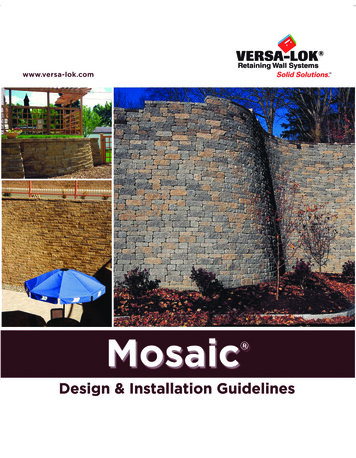
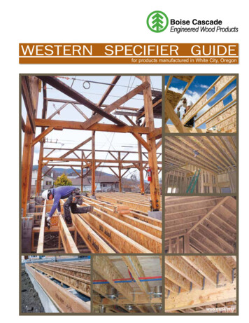
Introduction & Unit Specifications1VERSA-LOK STANDARD UNITS(Actual unit size and weight may vary slightly by region.)Standard units are made from high-strength, low-absorption concrete on concrete block machines.The Standard units’ solid characteristics make them resistant to damage before, during and afterconstruction in all climates, including shoreline applications.Height:6 inches152.4 mmWidth (face):16 inches406.4 mmWidth (rear):14 inches355.6 mmDepth:12 inches304.8 mmFace Area:2/3 ft20.062 m2Volume:.63 ft30.018 m3Weight:82 Ibs.Wgt/Face Area:123 Ibs./ftSolid VERSA-LOKStandardunits providesuperiordurability andconstructionstability.37.19 kg2599.84 kg/m2VERSA-TUFF PINLength:6.8 inches172.7mmDiameter:.48 inches12.2 mmMaterial:Glass-Reinforced NylonVERSA-LOK CAP UNITSHeight:3-5/8 inches92.1 mmWidth (face):14 inches355.6 mmWidth (rear): A Cap 12 inches304.8 mmB Cap16 inches406.4 mmDepth:12 inches304.8 mmWeight: A Cap40 lbs.18.14 kgB Cap50 lbs.22.68 kgversa-lok standard design and installation guidelines4
2VERSA-LOK Standard System OverviewPinningVERSA-LOK Standardunits interlock with non-VERSA-LOKStandard unitshave a uniquehole-to-slotpinning systemfor easy installationand superiorstructural integrity.corrosive VERSA-TUFF Pins (two per unit). Aswall courses are installed,pins are inserted throughholes in uppermost courseunits and are received inslots of adjacent lower course units.Pinning helps to align units in aMaximum allowable wall height for gravityconsistent 3/4-inch setback per course.walls varies with soil and loading conditions.Generally, with level backfill, good soils and noexcessive loading, VERSA-LOK Standard gravitywalls are stable to heights of 4 feet.Reinforced WallsWhen weight of units alone is not enoughto resist soil loads, horizontal layers of geosynthetics are used to reinforce soil behind walls.With proper soil reinforcement and design,Unreinforced WallsVERSA-LOK Standard walls can be constructedOn many projects, VERSA-LOK Standardto heights in excess of 50 feet. Geosyntheticsretaining walls work purely as gravity systems;do not act as tie-backs for wall faces. Rather,unit weight alone provides resistance to earthgeosynthetics and soil combine to createpressures. Frictional forces between units andreinforced soil structures that are strong andpin connections hold units together so wallsmassive enough to resist forces exerted on them.behave as coherent structures. Batter setbackIn soil-reinforced walls, Standard units simplyof wall faces offers additional resistanceretain soil between layers of geosynthetics andagainst overturning.provide attractive, durable faces.Refer to next page5versa-lok standard design and installation guidelines
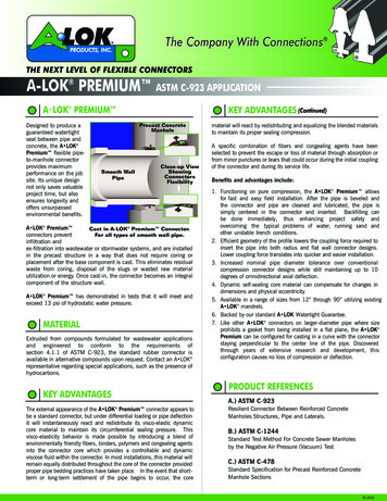
VERSA-LOK Standard Wall Components3Reinforced Wall Typical SectionThis cross section illustrates typical components of VERSA-LOK Standard retaining walls. MortarlessStandard walls are installed on granular leveling pads and do not require concrete footings belowfrost. The amount and layout of drainage materials and geosynthetic soil reinforcement is site/soildependent and should be designed by a qualified engineer. The 3/4-inch setback of each unit creates acant of approximately 7 degrees. Canted walls are structurally more stable than vertical walls becausegravitational forces “pull” walls into retained soil.versa-lok standard design and installation guidelines6
3VERSA-LOK Standard Wall ComponentsFoundationFoundation soils upon which segmental retainingwalls will rest must be stiff, firm, and haveMortarlessVERSA-LOKStandard retainingwalls do notrequire rigidconcrete footingsbelow frost.sufficient capacity to support wall systemweight. Any loose, soft or compressible materialmust be removed and replaced with properlycompacted backfill. The bearing capacity ofthe foundation soils should be addressed bya soils engineer.VERSA-LOK Standard retaining walls areinstalled on leveling pads consisting ofcoarse sand or well-graded angular gravel.The most commonly used material for levelingpads is that which is used locally as road baseCompacted granular leveling pads providea stiff but flexible base.aggregate. Granular leveling pads providestiff, yet somewhat flexible, bases to distributewall weights.If a contractor chooses to form leveling padsusing concrete, unreinforced pads should bemade of lean concrete mix (200-300 psi) and noRigid concrete footings extending below frostare not required or recommended. BecauseStandard units are installed without mortar,they are free to move slightly in relation to eachother. Flexibility of the leveling pads and wallunits accommodates freeze/thaw cycles withoutdamage to structures. VERSA-LOK Standardwalls, installed on granular leveling pads, havebeen successfully used on projects throughoutNorth America—including shoreline applicationsand walls exceeding 50 feet in height.7versa-lok standard design and installation guidelinesmore than 2 inches thick. To ensure correctStandard unit alignment, special care needs tobe taken to construct concrete pads that areexactly level. In rare situations where rigid,reinforced-concrete footings are required, theyshould be placed below seasonal frost depths.
VERSA-LOK Standard Wall ComponentsEmbedmentSoils and CompactionVERSA-LOK Standard segmental retaining wallsWith proper design, segmental retaining wallsusually have one-tenth of exposed wall heightscan be constructed within a wide variety of soilembedded below grade. For example, a wallconditions. Granular soils are preferred as fillwith 10 feet of height exposed above gradein the areas reinforced with geosynthetics;would have a minimum of 1 foot buried belowhowever, fine-grained soils such as clays aregrade—making a total wall height of 11 feet.acceptable. Usually, coarse soils require lessEmbedment should be increased for specialsoil reinforcement and are easier to compactconditions such as slope at the toe of walls,than fine soils. Problem materials like expansivesoft foundation soils, or shoreline applications.clays, compressible soils, or highly organic soilsEmbedment provides enhanced wall stability(top soil) should be avoided or properlyand long-term protection for leveling pads.addressed in designs.3Properlycompactedsoils are criticalto the performanceof a VERSA-LOKStandardretaining wall.Proper compaction of foundation and backfill soilis critical to long-term performance of retainingwall systems. Loose backfill will add pressure onwalls, collect water, cause settlement, and willnot anchor soil reinforcement materials properly.Foundation and backfill materials should becompacted to at least 95 percent of standardProctor density. (Proctor density is the maximumdensity of the soil achieved in a laboratoryusing a standard amount of compaction effort.)Generally, construction observation and testingfor proper soil type and compaction is providedby the project’s soils engineer.versa-lok standard design and installation guidelines8
3Water shouldbe directedaway from wallswith drainagestructures.VERSA-LOK Standard Wall ComponentsDrainage Within WallsSurface DrainageSegmental retaining walls are designedWall sites should be graded to avoid waterassuming no hydrostatic pressure behind walls.flows, concentrations or pools behind retainingDrainage aggregate (angular gravel, clear ofwalls. If swales are designed at the top of walls,fines) placed behind walls helps eliminateproperly line and slope them so water is removedwater accumulation. Because no mortar is usedbefore it can flow down behind walls.in VERSA-LOK Standard wall construction,water is free to weep through joints of installedGive special attention to sources of stormwaterunits. For walls greater than 3 feet in height,from building roofs, gutter downspouts, paveda perforated drain pipe is recommended at theareas draining to one point, or valleys in topography.base of the drainage aggregate to quicklyBe sure to guide flows from these areasremove large amounts of water.away from retaining walls. Slope the soil slightlydown and away from wall bases to eliminate9If high groundwater levels are anticipatedwater running along bases and eroding soil.or if the wall is along a shoreline, additionalIf finish grading, landscaping or paving is notdrainage materials behind and below reinforcedcompleted immediately after wall installation,fill may be required. Filter fabric may betemporarily protect the wall from water runoffrequired to prevent unwanted migration ofuntil adjacent construction and drainage controlfine soil particles into the drainage aggregate.structures are completed.versa-lok standard design and installation guidelines
VERSA-LOK Standard Wall ComponentsGeosynthetic ReinforcementGeosynthetic layers must be nominally tensionedGeosynthetics are durable, high-strength polymerand free of wrinkles when placed. Geosyntheticsproducts designed for use as soil reinforcement.are generally stronger in one direction—the rollHorizontal layers of geosynthetic provide tensiledirection. It is important that the high-strengthstrength to hold the reinforced soil together, so itdirection be placed perpendicular to the wallbehaves as one coherent mass. The geosyntheticface in one continuous sheet (no splices).reinforced soil mass becomes the retaining wall.Along the wall length and parallel to the face,Sufficient length and strength of geosyntheticadjacent sections of reinforcement are placedcan create a reinforced soil mass large enoughimmediately next to each other without overlapand strong enough to resist destabilizing loads.to create 100 percent coverage with no gapping,Geosynthetic layers also connect the VERSA-LOKand with special details for curves and corners.Standard units to the reinforced soil.The required type, length, vertical spacing,3Geosynthetics suchas VERSA-Grid reinforce backfillsoils, allowingconstruction ofstable VERSA-LOKStandard wallsexceeding 50 feetin height.and strength of geosynthetic vary with eachGeosynthetics are made from several types ofproject depending on wall height, loading,polymers that resist installation damage andslopes and soil conditions. A professionallong-term degradation. Geosynthetics areCivil Engineer (P.E.) should prepare a final,designed to interact with the soil for anchoragegeogrid-reinforced wall design for each project.against pullout and resistance to sliding.Geogrids, the most common soil reinforcementfor walls, are formed with an open, grid-likeconfiguration. Geotextiles (solid fabrics) arealso used. Product-specific testing determinesthe durability, soil interaction and strengthof each type of geosynthetic. The interactionof various geosynthetics with Standard units(connection strength) is also thoroughly tested.Geosyntheticsare designedto interactwith the soilfor anchorage.Geosynthetics provide tensilestrength to backfilled soils.versa-lok standard design and installation guidelines10
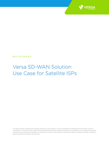
4EngineeringVERSA-LOK Standard walls are designed asstrength geogrid or adding more geogrid layerstraditional gravity walls. For unreinforcedby reducing vertical space between geogridwalls, the stabilizing weight of the batteredlayers. Potential pullout or internal slidingwall units is compared to the loading on theconcerns can be addressed by lengthening thewalls to ensure stability against overturninggeogrid layers.and sliding (page 12, Figure 1A). When theloading exceeds the stability of the units alone,Internal compound stability is the potentiala larger gravity mass is created from reinforcedfor compound failures starting directly behindsoil (page 12, Figure 1B).the wall, passing through the reinforced soilmass and exiting out the front face of the wall.Loading on segmental walls is dependent on soilThe wall design engineer can address internalconditions, surcharges, slopes, water conditionscompound stability by using a higher strengthand wall heights. Accurate knowledge of eachgeogrid type, adding geogrid layers, lengthen-of these properties is needed for a proper design.ing geogrid layers or improving the reinforcedSoil properties required for a segmentalsoil type.retaining wall design include the internal friction angle (φ) and soil unit weight (γ). Gener-For facial stability, the wall design engineer canally, the cohesion (c) of any fine-grained soils isaddress connection concerns by adding geogridconservatively ignored to simplify the design.layers (including shorter supplementary layers)or using a higher connection strength geogrid.To ensure stability of a reinforced retainingwall, the wall engineer must design the rein-For external stability, potential overturningforced soil mass large enough to resist loadsor sliding both can be addressed by lengthen-from outside the wall system (external stability)ing the geogrid layers to create a larger, moreand with enough layers of proper strengthstable reinforced soil mass.geosynthetic to keep the reinforced soil masstogether (internal stability). In addition, theEvaluation of geotechnical concerns generallydesign must have sufficient geosynthetic layersis the responsibility of the soils engineer. How-to keep units stable and properly connected toever, in some cases, these can be addressed bythe reinforced soil mass (facial stability).lengthening and strengthening the geogrid layers beyond what is required for the structuralFor internal stability, the wall designer canaddress potential overstress by using a higher11versa-lok standard design and installation guidelineswall design.
EngineeringUnreinforced WallReinforced Wall(Figure 1A)4(Figure 1B)Internal StabilityPulloutBreakage/OverstressExternal StabilityBase SlidingInternalSlidingInternal CompoundOverturningGeotechnical ConcernsGlobal SlopeStabilityBearing/Settlementversa-lok standard design and installation guidelines12
5Special Design ConsiderationsShorelinesVERSA-LOK Standard retaining walls performwell in shoreline applications. However, specialWith properdesign andreinforcement,VERSA-LOKStandard wallscan accommodatespecial siteconditions suchas water loads,slopes orsurcharges.design considerations are often necessary toensure that water pressures do not build upbehind walls. Special provisions may includegranular reinforced backfill, additional drainageaggregate, drainage behind reinforced soil massesand filter fabric. Protection of bases from waterscour, wave action and ice may also be necessary.See VERSA-LOK Technical Bulletin #1 for moreinformation on shorelines and retention pond protection.Loads Behind WallsSurcharge loads behind walls can substantiallyincrease amounts of required soil reinforcement.Common surcharge loads include parking areas,driveways, roads and building structures. Fordesign purposes, permanent loads like buildingsare considered to contribute to both destabilizingand stabilizing forces acting on walls. Dynamicforces like vehicular traffic are considered tocontribute to destabilizing forces only.Often, the highest surcharge loads are caused bygrading or paving equipment during construction.Heavy equipment should be kept at least 3feet behind the back of retaining wall units.Soil reinforcement designs should accommodateall anticipated surcharge loads—even if theywill occur infrequently or just once.13versa-lok standard design and installation guidelines
Special Design Considerations5TieringAesthetically, it may sometimes be desirableto divide large grade changes into tiered wallsections. However, upper wall tiers can addsurcharge loads to lower walls and necessitatespecial designs. To avoid loading lower walls,upper walls must be set back horizontally atleast twice the height of the lower walls.If walls are placed closer, lower walls mustbe designed to resist the load of upper walls.When properlydesigned, tieredVERSA-LOK retainingwalls will not onlyretain soil andsupport loads,but will alsodeliver anattractiveappearance.SlopesSlopes behind walls increase pressures,sometimes doubling soil loads compared tolevel backfills. Steep slopes below walls candecrease stability of wall foundations. Slopescan increase the amount of soil reinforcementneeded, especially the length. Generally, slopesabove or below walls should be no steeperthan 2:1 (horizontal:vertical).Several closely spaced tiered walls can create steep,unstable slopes. If tiered walls make a grade changesteeper than 2:1 (horizontal: vertical), global slopestability may need to be reviewed by a qualifiedsoils engineer.See VERSA-LOK Technical Bulletin #7 for moreinformation on tiered wall construction.versa-lok standard design and installation guidelines14
6The VERSA-LOKtechnical staff isavailable to assistin planning, layout,estimating andreferrals for finalengineering.Planning, Estimating & Final DesignsPlanningFinal DesignsPrior to design, accurate information needs toFinal wall designs may be provided prior tobe gathered, including soil conditions, proposedputting projects out for bidding. Alternatively,wall heights, topography, groundwater levelsprojects can be specified design/build. Withand surface water conditions. Proper permits,design/build projects, the specifiers provideowner approvals, utility clearances andwall layout information (line and grade) but noteasements should also be obtained.final engineering for the wall. Contractors submitbids based on this layout including estimatedMake sure that layouts account for minimumlabor, materials and final engineering costs.curve radii, wall setback, and area needed forContractors who are awarded projects retaingeosynthetic soil reinforcement. Be sure that alllicensed engineers to prepare final wall designs.wall components fit within property constraints.Verify that temporary construction excavationsA soils report prepared by a qualified geotechnicalwill not undermine foundation supports of anyengineer is needed to provide information onexisting structures or utilities. Considerationsreinforced and retained properties. The soilsshould also be given to site access for equipmentreport should also address slope stability andand materials.bearing capacity of foundation soils.EstimatingDesign/build specifications and sampleAccurately estimate and order requiredconstruction details are provided on pages 33materials including VERSA-LOK Standardto 46. This information, along with additionalunits, VERSA-TUFF Pins, VERSA-LOK Capdetails, is available in electronic format onunits, VERSA-LOK Concrete Adhesive, importedthe VERSA-LOK Specifiers’ Binder CD or on thebackfill, leveling pad materials, geosynthetic soilVERSA-LOK website at www.versa-lok.com.reinforcement and drainage materials. See theMaterials Estimation Worksheet on page 31 toFor walls more than 4 feet in height,help determine VERSA-LOK product quantities.most building codes require a final wall designFor reinforced-wall projects, the VERSA-Grid prepared by a licensed Civil Engineer (P. E.)estimating charts on page 32 provide approximateregistered in that state. VERSA-LOK and itsamounts of geogrid soil reinforcement necessarymanufacturers have a network of licensedto construct walls in various soil and loadingcivil engineers who are familiar with segmentalconditions. For tall walls or complex situations,retaining wall design. These individuals areVERSA-LOK staff engineers can prepare projectavailable for referrals to architects, engineersspecific preliminary designs to be used foror contractors with final wall design needs.estimation purposes.15versa-lok standard design and installation guidelines
Wall Construction7ToolsThe following tools may be helpful duringconstruction of VERSA-LOK StandardRetaining Wall Systems.VERSA-LIFTER Safety ProtectionShovel4-Foot LevelSmaller LevelThe VERSA-Lifter makes it easier to lift and4-Pound Sledge Hammerplace units—especially on the base course.Masonry ChiselTwo prongs on the lifter are inserted into pinholes in each Standard unit. Lifting the handleBrick Hammersecures the lifter to the unit and makes for easy,Tape Measurebalanced lifting and placement.Hand TamperVibratory-Plate CompactorCaulking GunStringlineFinishing TrowelBroomDiamond-Blade Concrete SawHydraulic SplitterTransit or Site LevelBackhoe or Skid-Steer Loaderversa-lok standard design and installation guidelines16
7VERSA-LOKStandard units areeasily modified bysplitting for atextured face,or by saw-cuttingfor a smooth side.VERSA-LOK Standard Wall ConstructionUnit ModificationSaw-CuttingDuring wall construction, it will sometimes beSaw-cuts are normally made using a gas-powerednecessary to split or cut VERSA-LOK Standardcut-off saw with a diamond blade. To cut aunits. Splitting will create attractive, texturedVERSA-LOK Standard unit, mark desired path ofsurfaces-similar in appearance to front faces ofcut on all unit sides. On a stable work surface,units. Saw-cutting will produce smooth, straightplace the unit face toward you with the top sidesurfaces. In general, units are split when modi-up, at a comfortable height. Make a straight cutfied portions will be visible. Units are cut whendown and 2 to 3 inches into the face. Movestraight edges are required to fit closely next tothe saw to the top of unit, and cut through topsmooth edges of adjacent units.using successively deeper cuts. Flip unit over andfinish by cutting completely through the bottom ofthe unit.SplittingTo split aVERSA-LOKStandard unit by hand, mark desired path ofsplit on unit top, bottom and back. Score alongthe top and bottom paths using a 2- to 3-inchmasonry chisel and heavy hammer. Next,place the unit on its face and strike along theback path. It is easier to split units on theground than on a hard surface. Unit shouldfracture nicely along paths. If many splits willbe required for a project, it may be helpful torent a mechanical or hydraulic splitter.If a cut-off saw is not available, a commoncircular saw and an inexpensive masonry blademay be used. Cut 1 to 2 inches deep alongthe path on the front face. Split the remainder ofthe unit. The vertical cut on the face of the unitwill fit closely against adjacent units - the splitportion will not be visible.17versa-lok standard design and installation guidelines
VERSA-LOK Standard Wall ConstructionExcavationLeveling PadExcavate just deep enough to accommodate thePlace granular leveling pad material and com-leveling pad (usually 6 inches) and requiredpact to a smooth, level surface. Leveling padunit embedment below grade. When necessary,should be at least 6 inches thick and 24 inchesalso excavate areas where geosynthetic soilwide. It should consist of coarse-grained sand,reinforcement will be placed. Required unitgravel, or crushed stone. Use a thin layer of fineembedment varies with wall height and sitesand on top of the leveling pad for final leveling.conditions. Generally, if grade in front of thewall is level, one-tenth of the exposed wall7Carefully planthe location andalignment of thewall base toensure top ofwall will be atdesired location.height should be buried (embedded) belowgrade. Additional embedment may be requiredfor special conditions, including slopes infront of walls, soft foundation soils andwater applications.To quickly construct longCompact soil at the bottom of excavation.sections of leveling pad,Do not place wall system on loose, soft, wetcreate forms by levelingor frozen soil—settlement may result. If the walland staking rectangularwill sit on previously backfilled excavationsmetal tubing along bothsuch as utility line trenches, be sure the entiresides of the plannedpad. Place and compactdepth of existing backfill is well-compacted.granular material withinIf necessary, over-excavate soft soils andthese leveled forms andreplace with properly compacted backfill.screed off excess.See VERSA-LOK Technical Bulletin #5 for moretips about leveling pad construction.If the planned grade along the wall front willchange elevation, the leveling pad may be steppedin 6-inch increments to match the grade change.Always start at the lowest level and work upward.Step the leveling pad often enough to avoidburying extra units while maintaining requiredunit embedment.versa-lok standard design and installation guidelines18
7VERSA-LOK Standard Wall ConstructionBase CourseTake time toensure a level basecourse—minorunevenness in thebase course willbe amplified anddifficult to correctafter severalcourses havebeen installed.Make sure that the leveling pad is level andUsing a 4-foot level, level units front to back,begin placing base course units. If the levelingside to side, and with adjacent units. Tap highpad is stepped, begin at the lowest point andpoints with a mallet or hand tamper until level.place entire length of lowest course beforeTake time to ensure a level base course. Minorproceeding to next course.unevenness in the base course will be amplifiedand difficult to correct after several courses havebeen installed.After base course has been positioned, placeand compact soil backfill behind the units.Also replace and compact over-excavated soil infront of units at this time. Backfill behind and infront of embedded units should consist of soil—do not use drainage aggregate.Align units using their backs or slots rather thantheir irregularly
VERSA-LOK StAndARd dESign And inStALLAtiOn guidELinES 4 Introduction & Unit Specifications 1 VERSA-LOK STANDARD UNITS (Actual unit size and weight may vary slightly by region.) Standard units are made from high-strength, low-absorption concrete on concrete block machines.