Transcription
FIRESTONE ROOFING SYSTEMSINSULATION AND MEMBRANEMECHANICAL ATTACHMENT GUIDE1 Pa g eFir est one At t achm ent GuideJuly 2015
Ta ble of Con t e n t sI nt roduct ion . 31.02 Subst rat e and Subst rat e Requirem ent s . 3General . 3Large Wall Opening Enhancem ent . 4Perim et er and Corner Definit ion . 5Adj oining Buildings . 61.03 I nsulat ion At t achm ent . 8General . 8At t achm ent . 8Mult iple Layers of I nsulat ion . 8Mechanical At t achm ent of I nsulat ion t o Subst rat e . 8Air Barriers . 9I nsulat ion Mechanical At t achm ent Pat t erns . 10I nsulat ion Adhesiv e At t achm ent Pat t ern . 11I .S.O. Twin Pack I nsulat ion Adhesive . 11Crit eria for Field Test ing I nsulat ion Adhesiv es for Adhesion t o Deck Subst r at es . 121.04Modified Bit um en Base Sheet At t achm ent . 13Base Sheet At t achm ent wit h any Modified Bit um en Cap Sheet . 13Base Sheet At t achm ent , Coiled Met al Bat t en, wit h a SBS Torch Cap . 13Base Sheet At t achm ent , MB 2” Barbed Plat es, w it h a SBS Torch Cap . 141.05Single- Ply Mem brane At t achm ent . 15Accept able Fast ener and Plat e Guidelines . 15Layout s in Chart Form . 19RubberGard EPDM ( St andard, LSFR, or FR) , 45 or 60 m il, Bat t en in t he Seam ( BI TS) . 19RubberGard EPDM ( St andard, LSFR, or FR) , 45 or 60 m il, Mechanically At t ached Sy st em ( MAS) . 20Rubber Gard EPDM MAX, 45 or 60 m il, Mechanically At t ached Syst em ( MAS) . 20Ult raPly TPO 96, 45 m il, Mechanically At t ached Syst em ( MAS) . 21Ult raPly TPO 96, 60/ 80 m il, Mechanically At t ached Sy st em ( MAS) . 21Ult raPly TPO 120, 45 m il, Mechanically At t ached Sy st em ( MAS) . 21Ult raPly TPO 120, 60/ 80 m il, Mechanically At t ached Sy st em ( MAS) . 22Ult raPly TPO 148, 45 m il, Mechanically At t ached Sy st em ( MAS) . 22Ult raPly TPO 148, 60/ 80 m il, Mechanically At t ached Sy st em ( MAS) . 221.06I nvisiWeld At t achm ent . 23To induct ion w eld t he m em br ane: . 23To heat w eld t he m em brane seam s: . . 23Enhancem ent Requirem ent s . 231.07Refer ences . 242 Pa g eFir est one At t achm ent GuideJuly 2015
IntroductionThe purpose of this guide is to reinforce installation techniques. The following guide is a supplement to be used inconjunction with the other guides located within the Technical Database. Reference to the specific Design Guide,Application Guide, Detail, Technical Information Sheets (TIS), and other Specifications is necessary to ensurethat the finished roof system is installed in compliance with Firestone requirements.NOTE: IF A PROPOSED APPLICATION FALLS OUTSIDE OF THIS SPECIFICATION, CONTACT YOUR BUILDINGSYSTEMS ADVISOR AT 800-428-4511 FOR ADDITIONAL INFORMATION.Within Firestone Specifications, reference is made to Firestone’s Mechanically Attached Systems.Mechanically Attached Systems by definition include: Batten in The Seam – BITSBatten or plates in the seam of the membrane.Plates are only allowed with reinforced membranes Mechanically Anchored System (Non-Reinforced Membrane) – MASLay out sheet battens on membrane, strip in Mechanically Anchored System (Reinforced Membrane) - Reinforced MASLay out sheet, set plates or battens on membrane, strip in Reinforced Mechanically Attached Strip – RMALay out strips over insulation; attach strip using plate or battens, place membrane overthe strips.1.02 Substrate and Substrate RequirementsGeneral1.The Firestone roof system depends on a suitable substrate to perform its intended function ofweatherproofing the building.I t is t h e r oofin g con t r a ct or ’s r e sponsibilit y for e n su r in g t h a t t h e su bst r a t e is a cce pt a ble for t h e Fir e st on er oof syst e m .2.The substrate to which the Firestone roof system is installed must: Be structurally sound Be dry, smooth, flat and clean Be free of sharp fins, or foreign materials that could damage the membrane Meet the minimum requirements for the system3.When using asphalt to adhere insulation to a structural concrete substrate, the concrete must be primedwith an ASTM D 41 asphalt primer. The primer is applied at a rate of 1½ to 2 gallons per 100 ft² (0.61 to0.82 L/m²).3 Pa g eFir est one At t achm ent GuideJuly 2015
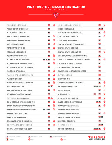
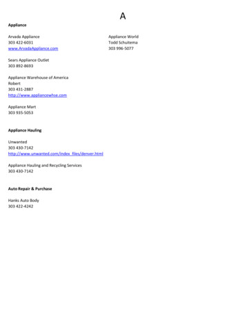
The Minimum Fastener Pullout Resistances for Specific SystemRoofing SystemMinimum Fastener PulloutFully Adhered Systems with Insulation MechanicallyAttached to Deck300 lbs (136.1 Kg)Single-Ply Mechanically Attached and Invisiweld400 lbs (181.4 Kg)Base Sheet Mechanically Attached to Deck300 lbs (136.1 Kg)Base Sheet Nailed to Deck40 lbs (18.1 Kg)Contact your Building Systems Advisor at 800-428-4511 if your substrate does not meet these minimumrequirements.Large Wall Opening EnhancementThe large wall opening enhancement is required when the sum of the various opening areas (w x h) is greaterthan 10% of the wall area.Perimeter ½ sheets are required in the hatched area as shown in the diagram below. It is common installationpractice to extend the perimeter along this entire building plan dimension to accommodate this rule, but it notnecessary.4 Pa g eFir est one At t achm ent GuideJuly 2015
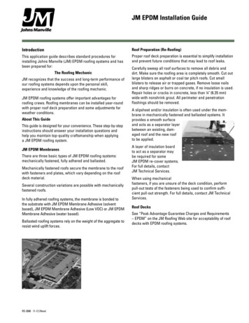
Pe r im e t e r a n d Cor n e r D e fin it ionOn the diagram above, “a” refers to the width of roof perimeters and a corner for Firestone warranted or FMapproved projects are equal to:For the building height, “h” is less than or equal to 60" (18 m)“a” is the smaller of0.1 times the building lesser plan dimensionor0.4 times “h”And“a” is never less than 4% of the building lesser plan dimension, but not less than 3" (0.9 m).For h greater than 60" (18 m)“a” is the smaller of0.1 times the building lesser plan dimensionAnd“a” is but not less than 3" (0.9 m). An ell is required in corner area equaling “2a”.When the roof slope is less than or equal to 10o (2:12 Slope); “h” is equal to the eave height.slope is greater than 10 (2:12 Slope): “h” is equal to the mean roof height.When the roofContact your Building Systems Advisor at 800-425-4511 for further clarification on these descriptions.5 Pa g eFir est one At t achm ent GuideJuly 2015
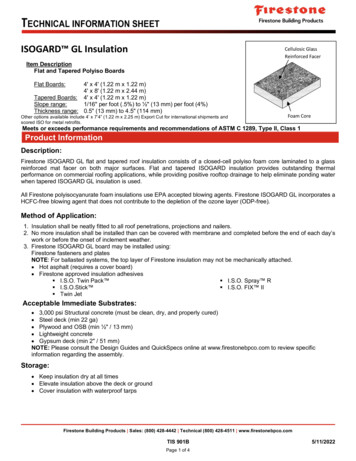
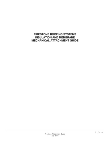
Adjoining Buildings6 Pa g eFir est one At t achm ent GuideJuly 2015
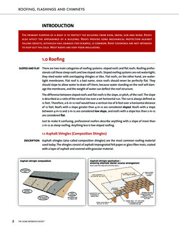
When a building adjoins another and has an elevation change of 3' or less then the perimeter and cornerenhancements can be omitted in that area. See the first diagram below. In the same building configuration andthe elevation change is 3' or greater, the higher building requires a standard building layout (perimeter and cornerenhancements) with the lower building omitting the perimeter and corner enhancements in that area. See thesecond diagram below.If there are concerns in regard to this enhancement, contact your Building SystemsAdvisor at 800-428-4511 for further clarification.7 Pa g eFir est one At t achm ent GuideJuly 2015
1.03 Insulation AttachmentGeneral1.2.3.Insulation must provide a suitable substrate for the proposed roof system as well as insulation for thebuilding.Insulation thickness requirements may vary for code compliance. Contact the local code or insurance officialbefore contacting your Building Systems Advisor at 800-428-4511.Refer to Insulation Technical Information Sheet (TIS) for specific spanning capabilities.At t a ch m e nt1. Insulation may be installed by various methods including fasteners, adhesives and asphalt. It is acceptableto combine fastener and adhesive attachment methods in multi-layer applications.2. Tapered insulation below the 1" (25.4 mm) minimum thickness must be fastened at a rate of one (1) fastenerand plate per two (2) ft² (0.22 sq. m). If possible, install the tapered insulation first, covered by the flat stock.3. Refer to specific Firestone Technical Information Sheets (TIS) for installation and fastening requirements.4. When a composite of two insulation layers is installed, the fastening pattern required for the top boardthickness must be used. A common fastener may be used to install multilayer applications. Some restrictionsapply to fastener length depending on standards used.Multiple Layers of Insulation1.2.Where overall insulation thickness is 2" (50.8 mm) or greater, Firestone recommends installing the insulationin two (2) or more layers.Insulation may be installed in one or multiple layer applications for the Firestone warranty. If installed inmultiple layers, the joints of each succeeding and adjoining layer should be staggered from the joints ofprevious layers by a minimum of 6" (152.4 mm) in each direction. When a composite of two insulation layersis installed, the fastening pattern required is dependant on the top board type and thickness. A commonfastener may be used to simultaneously fasten all layers to the structural deck.Mechanical Attachment of Insulation to Substrate1.2.3.Insulation must be fastened with appropriate Firestone fasteners and insulation plates.Firestone All Purpose (AP’s) fasteners are not acceptable, except for wood decks, for any 25, 20 yearsystems, 15-year re-cover, or Partial Tear off applications.Fastening rates and patterns may vary for code or regulatory compliance. Contact local code or insuranceofficial before contacting your Building Systems Advisor at 800-428-4511.8 Pa g eFir est one At t achm ent GuideJuly 2015
Fastening Patterns for Insulation inMechanically Attached Single Ply SystemsTop Layer of InsulationMaximum WarrantyTermInsulationISO 95 GL orResistaUp to 25-YearDens DeckDens Deck PrimeUp to 15-YearHailGardISOGard HDFiberTopThickness1.0" - 1.4"1.5" - 1.9"2.0" - 4"¼"½"ǫ"¼"½"ǫ"min. 1.5"½"½" - 1"Number of Fasteners per Insulation BoardNo Air BarrierWith an Air barrier4' x 4'4' x 8'4' x 4'4' x 8'Insulation Insulatio Insulation InsulationBoardn 8161281612812108161216AIR BARRIERS1. While some Firestone roof systems may require an air barrier to receive a Firestone warranty, the need for anair barrier, as well as the type, placement and location of the air barrier must be determined by a professionalarchitect or engineer.2. Air barriers systems are a component of building envelope systems that control the movement of air into andout of buildings.3. An air barrier may consist of a single material or of two or more materials which, when installed as a system,make up an air impermeable, structurally adequate barrier.4. Air barrier systems are generally comprised of building components and materials that have an airpermeability not exceeding 0.004 cfm/sf under a pressure differential of .3 in. water.5. No single component or material has the capability to provide a complete air barrier system for a building;therefore, air barrier systems include many components and materials that are interfaced with each other.Firestone recommends that the individual manufacturers of these products provide written certification thattheir products, when used together, meet this requirement.6. If the air barrier is to perform its intended role, it must meet a number of requirements: Continuity: the assembly must be linked together and sealed at all laps, seams, perimeters andpenetrations to ensure that there is no break in the air tightness of the envelope. Structural Integrity: The air barrier must be capable of resisting the imposed load or must besupported by one that can. It must be capable of resisting the strongest wind load acting as either apressure or suction without rupturing or breaking away from its support. The air barrier and its supportmust be sufficiently rigid to resist displacement. Air Impermeability: A major requirement of an air barrier is that it offers a high resistance to airflow. Durability: Durability depends largely on how a material reacts to a specific environment such asmoisture, temperature, ultra-violet radiation, and to the presence of other materials (incompatibility).9 Pa g eFir est one At t achm ent GuideJuly 2015
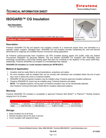
I n su la t ion M e ch a n ica l At t a ch m e n t Pa t t e r nsThe diagrams below show the required patterns for proper placement of approved fasteners and plates for insulation.These fastening patterns apply to standard 4' x 8' boards. The most common fastener density and patterns are shown.Certain specifications may call for increased densities of fasteners in the perimeter or corner areas. For these patternsand other non-standard fastener densities, contact your Building Systems Advisor at 4"24"48"48"24"48"12"24"96"96"Eight ( 8)96"Ten ( 10)Twelve ( "12"24"24"24"12"24"48"48"48"12"12"96"96"Fift een ( 15)Sixt een ( 16)12"12"Eight een ( 6"6"18"18"24"24"24"24"48"48"12"18"96"Twent y ( 20)12"12"12"48"12"12"96"Twent y- Three ( 23)96"Twent y- Four ( 24)10 P a g eFir est one At t achm ent GuideJuly 2015
"12"48"12"12"12"12"12"96"96"Twent y- Seven ( 27)Thirt y ( 30)96"Thirt y- Two ( 32)Insulation Adhesive Attachment PatternThe following Firestone Insulation Adhesives and application methods are acceptable:Firestone Insulation AdhesiveApplication MethodI.S.O. Twin PackI.S.O. FIX III.S.O. StickI.S.O. Spray SBead appliedBead appliedBead appliedBead applied or Spray appliedThe maximum size of any insulation board is 4' (1.2 mm) x4' (1.2 mm) regardless of the thickness.The rate of application, with a Firestone Insulation Adhesive, is four (4) ribbons per board to be installed in ½" to ¾" beadsspaced 12" on center for a standard 55 mph Red Shield warranty. The adhesive application does not increase ordecrease with the thickness of the board as in mechanically fastened insulation boards.Loose or unattached corners in insulation boards shall be repaired by the addition of fasteners and insulation plates asrequired.Refer to the Technical Information Sheet for specific information on these products: Foam Adhesives. If enhancementsare required or your project presents a unique situation, contact your Building Systems Advisor at 800-428-4511.I.S.O. Twin Pack Insulation Adhesive Ensure the use of a 4' x 4' board.Application surfaces must be even to ensure continuous adhesion.Immediately place insulation board into wet adhesive.The first and last adhesive bead should be inset 6" from the board edgefor a 12" o.c. application, inset 3" o.c. for 6" o.c. application and inset2" o.c. for 4" o.c. application.Immediately place insulation board into wet adhesive and weight with pailsof Bonding Adhesive or other available weight.See ribbon style diagram on right.I.S.O. FIX II Insulation Adhesive Ensure the use of a 4' x 4' board.Application surfaces must be even to ensure continuousadhesion.Immediately place insulation board into wet adhesive andweight with pails of Bonding Adhesiveor other available weight.The first and last adhesive bead shouldbe inset 6” from the board edge for a 12" o.c.application, inset 3" o.c. for 6" o.c. applicationand inset 2" o.c. for 4" o.c. applicat ion.See serpent ine st yle diagram on right .11 P a g eFir est one At t achm ent GuideJuly 2015
I.S.O. Stick Insulation Adhesive Ensure the use of a 4' x 4' board.Requires the PaceCart 2 DispenserApplication surfaces must be even to ensure continuous adhesion.Place board while adhesive is still wet and tacky. Adhesive shouldnot reach a tack-free state.The first and last adhesive bead should be inset 6" from the boardedge for a 12" o.c. application, inset 3" o.c. for 6" o.c. applicationand inset 2" o.c. for 4" o.c. application.Wait for the adhesive to develop a stringy body before placing theinsulation board into the adhesive. Immediately walk the board inand weight it down with pails of Bonding Adhesive or other availableweight.See serpentine style diagram on right.I.S.O. Spray S Insulation Adhesive Ensure the use of a 4' x 4' board.Performance of I.S.O.SPRAY S Adhesive should beperiodically monitored during the workday to verifythat sufficient rise, adhesion, and full mating is occurring.Requires spray rig equipment to apply.Application surfaces must be even to ensurecontinuous adhesion.Immediately place insulation board into wet adhesive.The first and last adhesive bead shouldbe inset 6" from the board edge for a 12" o.c.application, inset 3" o.c. for 6” o.c. applicationand inset 2" o.c. for 4" o.c. application.Wait for the adhesive to develop a stringy body beforeplacing the insulation board into theadhesive. Immediately walk the board in and weightit down with pails of Bonding Adhesiveor other available weight.See serpentine style diagram on right.Criteria for Field Testing Insulation Adhesives for Adhesion to Deck Substrates1. Prepare an area large enough to allow a 4' x 4' insulation board to be laid in place. Follow the appropriateFirestone Technical Information Sheet guidelines for surface preparation and list of acceptable substrates.Contact your Building Systems Advisor at 800-428-4511 if the substrate information is not listed.2. Apply the adhesive to the deck per recommended application rates and methods (12" o.c., ½" to ¾" bead).3. Allow the adhesive a minimum of 60 minutes to cure.4. After the adhesive has been allowed to cure, pull up on the adhered board by placing a hand under the corner orend of the board in the same direction as the ribbons. Make sure that the board is lifted by hand. Using tools toscrape the board sometimes disbonds the adhesive from the deck. This will not show whether the adhesive isperforming under uplift considerations. (If a tool is used, it should be used to pry or pop the board up).5. Observe the insulation and deck. The desired result is a delamination of the surface or board facer with adhesiveand facer residue remaining on the deck or the board breaks apart remaining adhered to the deck at the ribbons.If the board is lifted and the adhesive pulls/peels off the deck or decking is pulled up with the board,contact your Building Systems Advisor at 800-428-4511. This will be considered an unacceptablesubstrate.12 P a g eFir est one At t achm ent GuideJuly 2015
1.04Modified Bitumen Base Sheet AttachmentThe following information is intended to describe the base sheet attachment within a roofing system for Firestonewarranty purposes. This is only one component of the overall roofing system. For more information on thesystem warranty requirements, please visit the Technical Database at www.firestonebpco.com or contact yourBuilding Systems Advisor at 800-428-4511.Ba se Sh e e t At t a ch m e n t w it h a n y M odifie d Bit u m e n Ca p She e tAcce pt a bilit yPa t t e r nFirestoneFasteners andPlatesAny Base SheetInstall two rows staggered at 18"(457.2 mm) o.c., eachapproximately 13" (330.2 mm) infrom edge of sheet and in sidelaps at 12" (304.8 mm) o.c.Steel, Concrete,Plywood, OSB,Wood Plank,Gypsum orLightweightConcrete (22gauge pan)13 " O . C .See diagram on right.Lap12 " O . C .Acce pt a bilit yPa t t e r nFirestone CapNails and LWCBase PlyFastenersAny Base SheetPlywood, OSB,Wood Plank,Gypsum orLightweightConcreteInstall two rows staggered at 18"(457.2 mm) o.c., eachapproximately 12" (304.8 mm) infrom edge of sheet and in sidelaps at 9" (228.6 mm) o.c.18 " O . C .12" O . C .LapSee diagram on right.9" O .C .18" O . C .Ba se Sh e e t At t a ch m e n t , Coile d M e t a l Ba t t e n , w it h a SBS Tor ch Ca pAcce pt a bilit yPa t t e r nFirestone CoiledMetal Battenand FirestoneFastenersSBS Poly TorchBase, orSBS GlassTorch BaseInstall one row with a coiledbatten strip at 24" (304.8 mm)o.c. using Heavy Duty fasteners.Seams are lapped 4" and heatwelded.See diagram on right.Steel only Base Sheet side laps must be 4" (101.6 mm) and heat welded in this configuration. Then roll with a 20pound roller.Fasteners can be placed at 6", 12" (304.8 mm), 18" (457.2 mm) or 24" (609.6 mm) based on desiredwarranty.13 P a g eFir est one At t achm ent GuideJuly 2015
Base Sheet Attachment, MB 2” Barbed Plates, with a SBS Torch CapAcceptabilityFirestone MB 2"Barbed Platesand FirestoneFastenersSBS Poly TorchBase, orSBS GlassTorch BasePatternInstall one row with a coiled battenstrip at 18" (304.8 mm) o.c. usingHeavy Duty fasteners.Seams are lapped 4"(101.6 mm)and heat welded.See diagram on right.Steel only Base Sheet side laps must be 4" (101.6 mm) and heat welded in this configuration. Then roll with a 20pound roller.Fasteners can be placed at 6", 12" (304.8 mm), 18" (457.2 mm) or 24" (609.6 mm) based on desiredwarranty.Align Plate edge with laying line.14 P a g eFir est one At t achm ent GuideJuly 2015
1.05 Single-Ply Membrane AttachmentAcceptable Fastener and Plate GuidelinesFor the attachment of:Firestone FastenerRoofing Insulation(in combination withFirestone Insulation Plate)TISSheetNo.Fastener1001All-Purpose Fastener1002Heavy-Duty Fastener1005Concrete DriveFastener1006Polymer FastenerFirestoneBase SheetsFirestone(In combinationwith Firestone Batten StripsInsulation Plate)Seam oriesSee the specific fastener TIS for specific application data Do not use with polymer batten strips. ( Special bat t ens and plat es required)1007Firestone AccuTracKit1009HD Plus Fastener Insulation to steel and wood roof decks with AccuTrac installation equipment. A kit consists of bothfasteners and insulation plates for the AccuTrac tool. 1011Purlin Fastener Firestone Metal Batten Strips in Batten in the Seam (B.I.T.S.), M.A.S and Reinforced MAX,mechanically attached systems. Membrane and QuickSeam R.M.A. Strip to 12 – 18 gauge structural steel purlins.The Firestone Purlin Fastener can be used in conjunction with Firestone 2" Metal Plates, Firestone VPlates, or batten strips.1012LWC Base PlyFastener For the attachment of base sheets. Insulation may not be attached with LWC Base Ply Fastener 1013#12 Belted Fastener 1014#15 Belted Fastener Insulation to steel (18-24 ga.) and wood.Belted fasteners must be installed with the IF160 automatic installation tool available from SFS INTEC.When used for insulation attachment, the Firestone IFC/PH 2.75" x 2.75" (70 mm x 70 mm) plate isused. Insulation and membrane to steel (18-24 ga.) and wood.The #15 Belted fasteners must be installed with the IF160 automatic installation tool available from SFSINTEC.When used for membrane attachment, the Firestone 2 Ǫ" (60.3 mm) diameter plate is used.When used for insulation, the Firestone 2.75" x 2.75" (70 mm x 70 mm) plate is used. 1015Metal Cap NailingMachine1019HailGard Fastener(For the attachment of base sheets. Insulation may not be attached with nails of any kind)Cap nails are to be used to attach a base sheet to a wood deck and cannot be used to attachinsulation. Cap nails cannot be used to attach a base sheet through an existing built-up roof when theroof and insulation thickness is over ½"(12.7 mm). For use with Firestone HailGard Insulation and OSB to approved decks.plate required.No insulation Acceptable for use15 P a g eFir est one At t achm ent GuideJuly 2015
For the attachment of:TISSheetNo.Firestone PlatesRubberGard EPDM(Standard, LSFR, or FR)Bat t en in t heSeam( BI TS)MechanicallyAt t achedSyst em( MAS) Rubber Gard EPDM MAXULTRAPLY TPOBat t en in t he Mechanically MechanicallyAt t achedSeamAt t ached( BI TS)Syst em ( MAS) Syst em ( MAS) Wide Weld 11012" Metal Plate1102Polymer Fastener Plate1103V-Plate1104UltraPly 2 Ǫ" seam Plate For attaching Firestone UltraPly TPO membranes to approved substrates as required byFirestone Specifications and Details.For attaching Firestone Reinforced Perimeter Fastening Strips (RPF Strip) to approvedsubstrates as required by Firestone Specifications and Details. Insulation FasteningPlate1107Polymer FastenerInsulation Plate1108HD Seam Plate1109HD Plus Seam Plate For attaching Firestone RubberGard MAX membrane, Firestone RPF and QuickSeam RPFStrips, and Firestone QuickSeam R.M.A. Strip to approved substrates as required byFirestone Specifications and Details. For attaching insulation to approved substrates as required by Firestone Specifications andDetails. For attaching insulation to approved substrates as required by Firestone Specifications andDetails. For attaching Firestone UltraPly TPO membranes to approved substrates as required byFirestone Specifications and Details. 1111 For attaching Firestone Reinforced Perimeter Fastening Strips (RPF Strip) to approvedsubstrates as required by Firestone Specifications and Details. 1106 For attaching Firestone UltraPly TPO membranes to approved substrates as required byFirestone Specifications and Details. UltraPly TPO InvisiWeldPlateFor attaching Firestone UltraPly TPO membranes to approved substrates as required byFirestone Specifications and Details. Acceptable for use16 P a g eFir est one At t achm ent GuideJuly 2015
For the attachment of:TISSheetNo.Firestone Battenand TerminationBarsRubberGard EPDM(Standard, LSFR, or FR)Bat t en in t heSeam( BI TS)120112021204Coiled metal Batten StripMetal Batten StripMechanicallyAt t achedSyst em( MAS) Rubber Gard EPDMMAXULTRAPLY TPOBat t en in t he Mechanically MechanicallyAt t achedAt t achedSeamSyst em ( MAS) Syst em ( MAS)( BI TS) Wide Weld For anchoring membrane and flashing details to approved substrates as required byFirestone Specifications and Details. For anchoring membrane and flashing details to approved substrates as required byFirestone Specifications and Details. Polymer Fastener MetalFor anchoring RubberGard membrane to approved substrates as required by FirestoneBatten StripSpecifications and Details. 1205Termination barFor anchoring and sealing flashing terminations to approved substrates as required byFirestone Specifications and Details
1. Insulation must be fastened with appropriate Firestone fasteners and insulation plates. 2. Firestone All Purpose (AP's) fasteners are not acceptable, except for wood decks, for any 25, 20 year systems, 15-year re-cover, or Partial Tear off applications. 3. Fastening rates and patterns may vary for code or regulatory compliance.