Transcription
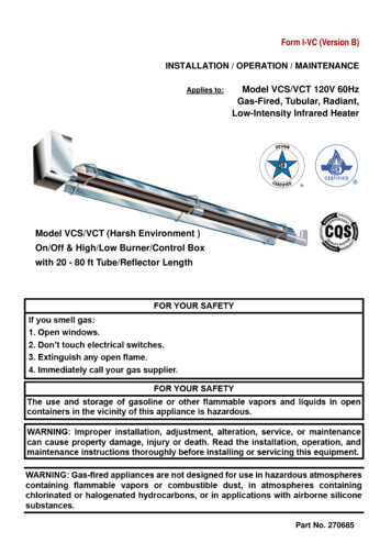
Form I-VC (Version B)INSTALLATION / OPERATION / MAINTENANCEApplies to:Model VCS/VCT 120V 60HzGas-Fired, Tubular, Radiant,Low-Intensity Infrared HeaterModel VCS/VCT (Harsh Environment )On/Off & High/Low Burner/Control Boxwith 20 - 80 ft Tube/Reflector LengthPart No. 270685
Introduction.Welcome to the new range of powered HarshEnvironment infrared heaters. Local regulationsmay vary and it is the installer’s responsibilityto ensure that such regulations are satisfied.and servicing is undertaken on radiant tubeheaters specified in these instructions, due careand attention is required to ensure that workingat height regulations are adhered toAll installation, assembly, commissioning andservice procedures must be carried out bysuitable qualified competent persons andconform with local building codes, or in theabsence of local codes, with the National FuelGas Code ANSI Z223.1/NFPA 54 or theNational Gas and Propane Installation CodeCSA B149.1.PLEASE READ this document prior toinstallation to familiarize yourself with thecomponents and tools you require at the variousstages of assembly.All Dimensions shown are in inches unlessotherwise stated.The manufacturer reserves the right to alterspecifications without prior notice.When assembling, installing, commissioningDocument Index.1 Installation Requirements1.1 Health & Safety1.2 Heater Suspension1.3 Clearance to Combustibles1.4 Gas Connection & Supply Details1.5 Electrical Connections1.6 Ventilation Requirements1.6.1 Unvented Units1.6.2 Vertical Venting1.6.3 Horizontal Venting1.7 Fresh Air Intake1.8 Technical Details3 Start Up Instructions3.1 Tools Required3.2 Start up procedure4 Servicing Instructions4.1 Tools Required4.2 Burner Description4.3 Burner Removal4.4 Burner Gas Injector Servicing4.5 Burner Head and Electrode Servicing4.6 Combustion Fan Assembly4.7 Radiant Tube Servicing4.8 Reflector Servicing4.9 Cleaning of Vent4.10 Re-commissioning after Service2 Assembly Instructions2.1 Tools Required2.2 Assembly Notes2.2.1 Tubes2.2.2 Turbulators2.2.3 Brackets2.2.4 Couplers2.2.5 Reflectors2.2.6 End Caps (optional)2.2.7 Bends (where required)2.2.8 Burner/Fan Assembly2.2.9 Heating Configurations2.2.10 Detailed Assembly Drawings5 Spare Parts6 Troubleshooting Guide7 Replacing Parts7.1 Burner Controller Replacement7.2 Air Pressure Switch Replacement7.3 Gas Valve Replacement7.4 Optional Extra Kits8 User and Operating Instructions8.1 To Start Heater8.2 To Switch Off Heater8.3 Servicing1. Installation Requirements.1.1Health and SafetyA.Heater is intended for heating outdoor ornon-residential indoor spaces and shouldonly be installed where flammable gasesor vapours are not generally present.B.Heaters may be suspended eitherhorizontal or at any angle. See section1.3 for clearance dimensions.C.The installation must conform with localbuilding codes or, in the absence of localcodes, with the National Fuel Gas Code,ANSI Z223.1/NFPA 54 or the NaturalGas and Propane Installation Code, CSAB149.1.2D.The unit shall be electrically grounded inaccordance with National Electric CodeANSI/NFPA 70 and Canadian ElectricalCode CSA C22.1.E.The heater may be installed in aircrafthangars in accordance with the Standardfor Aircraft Hangars, ANSI/NFPA 409 andin automotive garages when installed inaccordance with the Standard for ParkingStructures, ANSI/NFPA 88A, or theStandard for Repair Garages, ANSI/
F.NFPA 88B, or the Canadian Natural Gasand Propane Installation Code, CSAB149.1, and are so marked.Ensure that minimum clearances will bemaintained to vehicles parked below theheater.They must be adequately fixed and designed tocarry the whole weight of the heater. In theevent of suitable roof steelwork beingunavailable, additional steelwork should be fittedto enable vertical hangers to be used forsuspending the heaters.These heaters are approved forinstallations between 0 - 2000ft (0 610m) for the US and 0 - 4500 ft(1370m) for Canada. Consult factory forinstallations above these heights in theUSA.These methods are illustrated in Figure 1. Ifthere are any doubts as to the strength orsuitability of roof steelwork to which heaters areto be suspended, please refer to a Consultant,Architect or owner of the building.It is recommended that the heater is raised to itsfinal position once the assembly of the tube/bracket/reflector has been completed. Longertube assemblies may be raised in more thanone sub-assembly with final tube connectionmade in the air.Note: Any outdoor installations must beinstalled with a vent cap at the inlet andthe flue end.1.2Heater SuspensionEnsure that the installer uses the burner roofsupport mounting bracket when suspending theheater. This is situated on the front of theburner. When packed the bracket is reversedand must be turned to its correct state formounting. (ref page 18.)Attachment to the heater support lugs shouldbe made by D shackle. The hangingattachments to overhead steelwork etc. mustbe purpose made to sound engineeringpractice or supplied by others.WARNING:If not installed, operated and maintained in accordance with the manufacturer’s instructions,this product could expose you to substances in fuel or from fuel combustion which areknown to the state of California to cause cancer, birth defects or other reproductive harm.U TUBE VARIANTSEYE HOOKSNOTE.HOOKS ARE TOBE CLOSED UPAFTER ASSEMBLYSuitable Chain2/0 GA AUSTENDCHAIN55 SUSPENSIONBURNEREND3ON U TUBE VARIANTS THE HEATER SHOULDSLOPE DOWNWARDS TOWARDS THE BURNERHEAD AND ON LINEAR VARIANTS SHOULD SLOPEDOWNWARDS TOWARDS BURNER BY APPROX. ½”FOR HORIZONTAL INSTALLATIONSFigure 1. Recommended Methods of Heater Suspension.
1.3as plastics, vinyl siding, canvas, tri-ply, etc.) maybe subject to degradation at lower temperatures.Clearance to Combustibles.Minimum clearance to combustibles are shownin (Table 1) presents a surface temperature of 90 F (50 C)above room temperature.Building material with a low heat tolerance (suchTable 1It is the installer’s responsibility to assure thatadjacent material are protected from degradation.Radiant Tube Heaters must be shieldedand 24” clearance must be maintainedbetween any PVC Cladding and the shieldingof the Radiant Tube Heater.Clearance to Combustibles, inches (cm)BurnerRatingAB6074 (188)29 (74)8074 (188)100B1C1C2C3D1D2E41 (105) 6(16) / 3(8)*8 (21)22 (56)8 (21)14 (36)10 (26)29 (74)41 (105) 6(16) / 3(8)*8 (21)22 (56)8 (21)14 (36)10 (26)74 (188)32 (82)41 (105) 6(16) / 3(8)*8 (21)22 (56)8 (21)16 (41)10 (26)12574 (188)39 (99)47 (120) 6(16) / 3(8)*8 (21)22 (56)20 (51)18 (46)10 (26)15074 (188)39 (99)48 (122) 6(16) / 3(8)*8 (21)22 (56)20 (51)18 (46)10 (26)17086 (219)48 (122)48 (122) 6(16) / 3(8)*11 (28)22 (56)20 (51)20 (51)10 (26)20086 (219)48 (122)48 (122) 6(16) / 3(8)*11 (28)22 (56)20 (51)20 (51)10 (26)* distance with end caps fitted.Minimum clearance from the heater must be maintained from vehiclesparked below heater. In all situations, clearances to combustibles must bemaintained. Signs should be posted in storage areas to specify maximum stacking height tomaintain required clearance to combustibles. Such signs must either be posted adjacent tothe heater thermostats or in the absence of such thermostats in a conspicuous location.Refer to mounting clearance tables.WARNING:4
B5EC1ServicedistanceAboveBurnerEnd view.SideventedASideunventedAboveReflectorBurner end.C2BelowheaterBB1Above outletunventedEndunventedD1Outlet end.C3WARNING!Ensure thatthere is adequateprovision in the building forEnsure that there is adequatecombustion and ventilation airprovision in the building forsupply. Installation must meetcombustion and ventilation airminimum requirements andsupply. Installation must meetappliciable codes.minimum requirements andappliciableapplicable codes.D2Return end onU tube heaterAAngled view.Figure 2 Clearance to Combustibles (Standard indoor reflectors).The minimum clearances to combustible materials are given in the tables below. Theseminimum distances MUST be adhered to at all times. Adequate clearance MUST be providedaround air openings into the combustion chamber and there MUST be suitable clearance foraccessibility and for combustion / ventilating air supplies.0 to 55
1.4Figure 3. Correct orientation of Ball ValveGas Connection and SupplyWARNING: Before installation, checkthat the local distribution conditions,nature of gas and pressure, and adjustmentof the appliance are compatible.Gas FlowThe gas connection on the heater is ½” N.P.Tinternal thread.Gas FlowInjector sizes and manifold pressure for theburners are shown in the table 4. The gassupply piping and connections must be installedso that the minimum pressure stated isachieved.Figure 4. Correct Installation of FlexibleGas ConnectionA gas shut off valve and union should be fittedin the gas supply line close to the heater and a⅛” N.P.T plugged tapping, accessible for testgauge connection, provided immediatelyupstream of the appliance gas inlet.It is essential to provide some flexibility in thefinal gas connection by use of an approvedflexible gas connector. (See Fig 4.)Take care when making a gas connectionto the heater not to apply excessive turningforce to the internal controls.Care must be taken to observe the minimumpipe bend diameter (minimum 10”, maximum14”) & pipe expansion distance (minimum 1⅛”,maximum 3¾”).The correct installation as shown will allowfor approx 4” of movement due toexpansion.* Connector must be certified for use on a radiant tube typeinfrared heater and must comply with Standard forConnectors for Gas Appliances, ANSI Z21.24/CSA 6.10 orwith the Standard for Elastomeric Composite Hose andHose Couplings for Conducting Propane and Natural Gas,CAN/CGA 8.1.Table 3For heaters up to 150,000Btu/h, ½” ID x 24” longFor heaters 150,000Btu/h and above, ¾” ID x 36” longNOTE: For Canada all heaters MUST use a hose 36” long(See Table 3)HOSE SIZEUSACANADA3/4”CE4CONTACTFACTORYWARNING: FIRE OR EXPLOSION HAZARD - Expansion of the radiant pipe occurs witheach firing cycle causing the burner to move with respect to the gas line. This canresult in a gas leak producing an unsafe condition. It is therefore essential to provide someflexibility in the final gas line connection by use of an approved flexible connector as shownin the drawings.6
CONNECTOR MUST BE INSTALLED IN A “U” CONFIGURATION. FOR HEATERSUPTO 150,000 BTU/H, A 24” LONG CONNECTOR OF AT LEAST ½” ID MUST BEUSED. FOR HEATERS ABOVE 150,000 BTU/H, A 36” LONG CONNECTOR OF ATLEAST ¾” NOMINAL ID MUST BE USED.Table 4 Gas Supply PressuresNatural GasLP/Propane GasRequired Gas Pressure (in W.C)7.011.0Maximum Supply Pressure (in W.C)14.014.0Gas TypeConnection ½” N.P.T threadGas Supply1.5Electrical ConnectionsImportant: All electrical work should be done by aqualified electrician in strict accordance with theNational Electrical Code ANSI/NFPA 70 or CanadianCodes CSA C22.1.WARNING: Before making electricalconnections, switch OFF the mainelectrical disconnect. There may be morethan one disconnect switch. Lock outand tag switch with a suitable warninglabel. Electrical shock can causepersonal injury or death.The electrical supply to theheater is by three wires: hot(Live), neutral and groundconnections.This appliance must be electrically groundedInstall in accordance with allstate & local codes.Supply 120V 60Hz single phase.Standard heater 0.16HP.Current rating 1.2 amp max (inductive).Fuse: external 3 amp.Where alternative manufacturerscontrols are used, please refer totheirinstructionsfortheirinstallation details.Figure 5a. External Wiring Schematic. (VCT)24V AC 2-StageThermostat (Ext.)Burner 1R24V ACTerminalsCW1W2(120V AC FanTerminals)BKRCW1Burner 2W2BKBLRORCW1W2F1F1F2F2EENNLGEWN120V ACSupplyNotes:Use 18/4 class 2 thermostat cable betweenheater(s) and thermostat.120V ACSupplyKEY:BK-BLACKBL-BLUER-REDO-ORANGEG-GREEN24V ACTerminals24V ACTerminals(120V AC FanTerminals)LBKEGNWMax. length @ 18 Awg (0.8mm²) 100ft.No more than 2 burners can operate from onethermostat as supplied. However, a control is
120V AC supply is still present at each burnerwhen the thermostat is switched off.available from the manufacturer that allows upto 8 burners to be operated from onethermostat as a single zone.When servicing heaters ensure the electricitysupply is isolated from the mains supply.Figure 5b. Single and Multiple Heater Installations 120V Control (VCS)GTBKGNDL2L1 (HOT)W120V 60Hz 1 PhSupply circuitBK120V110VThermostatThermostatBurner 1BKWOther burnersGKEY:G-GREENW-WHITEBK-BLACKother burnersFigure 5c. Multiple Heater Installations 24V Control (VCT)R30VATransCW1TCRRBKS-070024V ThermostatGWGL2L1BKRelayBurner 1GNDL2L1 (HOT)120V 60Hz 1 PhSupply circuitOther burnersFan center relay(Suppled by others)WBKKEY:G-GREENW-WHITEBK-BLACKR-REDGBKother burners8
Figure 6. Internal Burner Wiring Diagram. (VCS)O p tio n al24V sin glestageT h erm os tatW120V A CS up plyNKEY:B L - B LU EB K - B LA C KBR - BROW NGR - GREYG - G REENW - W H IT EY - Y E LLO WO - ORANGEP - P U R P LEWEGLNBKGBKEWFW1GBKGW120V A C FanT erm in alsOBLBRCBKR24V S tatT erm in alsRNW1OCBLBRREL120v/24V A C 60H zYP ow er O N (red )BRYWBKEP re ss ure S w itchBLBRT ra ns fo rm erGRPCOMCXRW1PS0PS1MVINDL1PGREG as C o n tro lGMCEGas ValveBLGRBRBROYYPBKBKB u rn er O n (am b er)N O T E S :P ow er O n light is perm anently illum inated w hen 120V / 60 H z A C external supply is connected to burner.A dd itiona l w iring is requ ired to in stall a th erm ostat and / or tim e clock.W ire specification:- 18 A W G (1.0m m ²), T ri-rated, 105 CIf any of the original wire as supplied with the appliance must be replaced, it must be replacedwith wiring material having a temperature rating of at least 220 F/105 C9
Figure 7b. Internal Burner Wiring Diagram. (VCT)24V Tw o stageTherm ostatWK EY :B L - BLU EB K - B LA C KBR - BROW NGR - GREYG - G R E ENK - P IN KR - REDW - W H ITEY - YE LLO WO - ORANGEP - PU R P LENWEGLNBKGE120V A CS upplyWRF2GBKGWBKRF1W2KW1OBLBRC120V A C FanTerm inalsBK24V A C S tatTerm inalsRNW2KW1OCBLBRRELEYWBKEY120V /24V A C 60HzP ow er O N (red)BRP ressure Sw itchBLBRTransform erGRPLow FireH igh FireR elayRBLBK12A2A124V A CR E LA Y24142111NC(am ber)GRKC O ILH igh FireNOCOMCOMXCRW1PS0PS1MVINDL1PGRKG as C ontrolMCHIGas ValveBLGRBRBROYYPRBKR22N O TE S:P ow er O n light is perm anently illum inated w hen 120V / 60 H z A C external supply is connected to burner.A dditional w iring is required to install a therm ostat and / or tim e clock.W ire specification:- 18 A W G (1.0m m ²), Tri-rated, 105 CIf any of the original wire as supplied with the appliance must be replaced, it must be replacedwith wiring material having a temperature rating of at least 220 F/105 C10
1.6 Vent Requirements and Details1.6.1 Unvented unitsHeaters may be installed without a ventproviding the governing building codes are metand consideration is properly given topossibilities of condensation on cold surfaces.Installationshallmeettherequirements when unvented: followingInternal volume of the heated room mustbe greater than 214cu.ft. per 100 BTUper hour of heaters installed.ORNatural or mechanical means shall beprovided to supply and exhaust at least 4CFM per 1000 BTU per hour input ofinstalled heaters.Combustion gasses shall not impinge oncombustible materials.1.6.2 Vertical ventingThe heater can be installed with a vertical vent.All vent piping should be adequately supportedfrom the building structure and terminated withan approved terminal. The maximumrecommended vent length is 25ft (7.6m) witha maximum of two 90 elbows. Allconnections should be properly sealed.(refer fig 8a)1.6.3 Horizontal ventingIndividual units can be vented horizontallythrough side walls. Recommended terminalsare part numbers 111848 for 4” and 111850 for6”.Distances from adjacent public walkways,adjacent buildings, openable windows andbuilding openings, consistent with the NationalFuel Gas Code, ANSI Z223.1/NFPA 54 or theNatural Gas and Propane Installation Code,CSA B149.1.Maximum length of vent is 25ft (7.6m) with two- 90 elbows.Runs of 12ft (3.6m) or shorter can use4” (101mm) diameter vent. Runs over 12ft(3.6m) should use 6” (152mm) vent pipe.Any portion of vent that passes through acombustible wall must be insulated, or use anapproved insulating thimble.Standard vent terminals must extend at least6” (152mm) from the wall and at least24” (609mm) from any combustible overhang.Protect the building material from degradationby the vent gasses.Vent joints should be sealed and securedaccording to the vent manufactures instructions.Should condensation occur the vent should beshortened or insulated.The terminal should be at least 3ft (0.91m) awayfrom any air intake to the building.If the heater is equipped with ducted combustionair, the vent terminal must be at least 3ft(0.91m) away from the air inlet and locatedhigher than the inlet.The vent terminal must be installed at a suitableheight above the ground to prevent blockage bysnow.1.7Fresh Air IntakeWhenever the heater is installed in locationswhere airborne dust or other pollutants arepresent, a fresh air supply should be ducted tothe burner.A fresh air duct of 4” (101mm) diameter shouldbe installed from the fresh air to the air intakeconnection on the burner housing. A flexiblejointing piece should be installed at the burnerconnection with hose clamps to facilitateexpansion and contraction.The maximum recommended length air duct is25ft (7.6m) and the maximum number of elbowsis two. The minimum length is 18” (456mm).The location of the fresh air duct inlet must bewhere it will receive dust free clean air. An inlet11
Figure 8.a Vertical Venting.CODE APPROVED VENTTHROUGH ROOFcap with bird screen must be fitted atthe inlet of the duct. If the duct inletis located above the roof theunderside of the inlet terminal mustbe at least 2ft (0.61m) above rooflevel and at least 10” (254mm)above any projection on the roofwithin 7ft (2.1m) of the inlet. Intakepipe, fittings and sealant are notfurnished by the manufacturer. Referfig 8c & 8dROOFSEALAPPROVEDCAT III VENT PIPEALUMINUMSUPPLIED BY OTHERS4" (101mm) O.D. OR6" (152mm) O.D. FLUE12'-0" (3.66m)12'-0" (3.66m)(APPROXIMATEMAXIMUM DIMENSIONS)SEAL JOINTS WITHHIGH TEMPERATURE SILICONE4" (101mm) TO 6" (152mm) DIA. CATALUMINUMADAPTERIII ADAPTERREQUIRED ONLY FOR 6" (152mm) DIA. VENTEND OF RADIANT TUBEVENTADAPTORELBOWVENTCAT III ELBOWREFLECTORFigure 8.b Horizontal Venting.SUPPLIED BY OTHERSENSUREJOINTSARESEAL ALLJOINTSWITHSEALEDHIGH TEMPERATURESILICONE6" (152mm)COLLAR4" (101mm) TO 6" (152mm) DIA.ALUMINUMADAPTERAPPROVEDCAT 3 VENTPIPEREQUIRED ONLY FOR 6" (152mm) DIA. VENTSCOUPLERREFLECTORINLET WITHBIRD SCREENWALLEND OFRADIANTTUBEALUMINUM 4" (101mm) O.D. MAXIMUM LENGTH 12'-0" (3.66m)ALUMINUM 6" (152mm) O.D.MAXIMUM LENGTH 25'-0" (7.62m)(PLUS A MAXIMUM OF 2 x 90 ELBOWSBENDSALUMINUM 4" (101mm) O.D. PIPEELBOWSMAX LENGTH 25'-0" (7.62m) WITH 2-90 LONG RADIUS BENDS4.25”(108mm)O.D.O.DFLEXIBLEFLEXIBLEDUCT4" (106mm)DUCTCLAMPSNOTE: The ventterminal should beinstalled so as to be inthe same atmosphericpressure zone as thecombustion air inlet ofthe applianceFigure 8.d Wall Terminal Intake Kit.TERMINAL36" (914mm) MIN CENTERSFigure 8.c Fresh Air Ducted Intake.36" (914mm) MIN CENTERSTERMINALBURNERWALLINLET WITHBIRD SCREEN6" (152mm)12SEAL JOINTS WITHSILICONE OR DUCT TAPE
1.8Technical Details - Table 5a (VCS)1No of InjectorsGas Connection½” N.P.TElectrical Supply120 volt 1 phase 60Hz4” or 6” (101mm or 152mm)Vent size (in)120 volt 1 phase 60HzUnitary Fan Motor Details1.2A MAXCurrent RatingElectronic Program Start up with Spark IgnitionIgnitionNatural GasLP GasMin. HeaterLengthMax. HeaterLengthMin. HeaterLengthMax. HeaterLengthBTU/HrBTU/HrS ft (m)S ft (m)U ft (m)U ft (m)6060,00060,00020 (6.1)40 (12.1)20 (6.1)40 (12.1)8080,00080,00020 (6.1)40 (12.1)20 (6.1)40 (12.1)100100,000100,00030 (9.1)50 (15.2)40 (12.1)40 (12.1)125123,500125,00040 (12.1)60 (18.3)40 (12.1)60 (18.3)150150,000150,00040 (12.1)70 (21.3)40 (12.1)60 (18.3)170200169,000169,00050 (15.2)80 (24.4)60 (18.3)80 (24.4)200,000N/A50 (15.2)80 (24.4)60 (18.3)80 (24.4)ALTITUDE CONVERSION KITS ARE AVAILABLEBurner RatingNatural Gas 0-2000 ft (0-610m)LP Gas 0-2000 ft (0-610m)Burner OrificePlateInjectorInjectorPressureBurner OrificePlateInjectorInjectorPressurePart No.Part No.inches WCPart No.Part No.inches 02699462704103.5BurnerRatingNatural Gas 2001-4500 ft (611-1370m)N/ALP Gas 2001-4500 ft (611-1370m)CANADAONLY 10%DERATEBurner OrificePlateInjectorInjectorPressureBurner OrificePlateInjectorInjectorPressureBurner RatingPart No.Part No.inches WCPart No.Part No.inches 313N/A
Natural GasCombustion FanDetailsBurnerRatingFan TypeLP GasPressureSwitchOrificePart No.Part No.Combustion FanDetailsFan 7150269926170269930270475200270476270386U20U4060 80 Part No.Part ad269931270387269937N/AU TubeBurnerRatingPressureSwitchOrificePart No.60100All typesStraight TubeU80S10S20S30S40S50 S60S70100 125 150 S80170 200 14
1.8Technical Details - Table 5b (VCT)1½” N.P.T120 volt 1 phase 60Hz4” or 6” (101mm or 152mm)120 volt 1 phase 60Hz1.2A MAXElectronic Program Start up with Spark Ignition24Vac 60Hz 1.5A Max. total loadNo of InjectorsGas ConnectionElectrical SupplyVent size (in)Unitary Fan Motor DetailsCurrent RatingIgnitionThermostatALTITUDE CONVERSION KITS ARE AVAILABLEBurnerRatingNatural GasLP GasHigh / LowHigh / LowRate BTU/Hr Rate BTU/HrMin. HeaterLengthMax. HeaterLengthS ft (m)S ft (m)Min. Heater Max. HeaterLengthLengthU (ft)U (ft)6060,000/45,00060,000/45,00020 (6.1)40 (12.1)20 (6.1)40 (12.1)8080,000/60,00080,000/60,00030 (9.1)40 (12.1)40 (12.1)40 (12.1)100100,000/65,000100,000/65,00030 (9.1)40 (12.1)40 (12.1)40 (12.1)125123,500/95,000125,000/95,00030 (9.1)50 (15.2)40 (12.1)40 (12.1)150150,000/100,000 150,000/100,00040 (12.1)60 (18.3)40 (12.1)60 (18.3)170169,000/125,000 169,000/125,00050 (15.2)70 (21.3)60 (18.3)60 (18.3)200200,000/150,00050 (15.2)70 (21.3)60 (18.3)60 (18.3)N/ANatural Gas 0-2000 ft (0-610m)Burner OrificePlateInjectorPart No.Part No.60269941270400802699422704023.9BurnerRatingLP Gas 0-2000 ft (0-610m)InjectorPressureBurner OrificePlateInjectorPart No.Part No.2699482703982.32699492703995.23.0Inches WC.High Low4.22.4InjectorPressureInches WC.High 9532704036.83.92002699462704104.62.8Natural Gas 2001-4500 ft (611-1370m)CANADAONLY 10% Burner OrificeInjectorInjectorDERATEPlatePressureN/ALP Gas 2001-4500 ft (611-1370m)Burner OrificePlateInjectorPart No.Part No.269948270398InjectorPressureBurnerRatingPart No.Part 462704104.42.6Inches WC.High Low4.12.315N/AInches WC.High Low6.03.4
Natural GasLP GasCombustion FanDetailsBurnerRatingFan TypePressureSwitchOrificePart No.Part No.Combustion FanDetailsFan TypeOrificePart sureSwitchBurnerHeadPart No.Part 7U20U40 269936N/AU TUBEBurner RatingAll typesSTRAIGHT TUBEU60S10S20S30S40 S50S6080 100 125 150 S70170 200 TUBE TYPE MATERIALCalcoat Mild SteelMIN DISTANCETO BEND60TUBE 1REMAINDER10 (3.1)80TUBE 1REMAINDER15 (4.6)100TUBE 1REMAINDER15 (4.6)125TUBE 1REMAINDER15 (4.6)150TUBE 1REMAINDER20 (6.1)170TUBE 1 & 2REMAINDER25 (7.6)200TUBE 1 & 2REMAINDER25 (7.6)Burner RatingOptions * Not available on LP Gas1234567All standard units fitted with unvented vent, natural gas and aluminized reflectors.1 off 180 ‘U’bend or upto 2 off 90 ‘L’bends can be fitted at no less than 50% of the total heater length.4” (101mm) or 6” (152mm) vent terminal.Combustion air kit.Reflector end caps.Altitude conversion kit.Propane and propane altitude conversion kit.16
2. Assembly Instructions.PLEASE READ this section prior toassembly to familiarize yourself with thecomponents and tools you require at the various stages of assembly. Carefully open thepackaging and check the contents against theparts and check list.Please ensure that all packaging isdisposed of in a safe environmentallyfriendly way.For your own safety we recommend theuse of safety boots and leather facedgloves when handling sharp or heavy items. Theuse of protective eye wear is alsorecommended.The manufacturer reserves the right to alterspecifications without prior notice.2.1Tools Required.Suitable alternative tools may be used.The following tools and equipment are advisableto complete the tasks laid out in this PhillipsScrewdriverWrenchSet5/16”Drive3/16” (5mm)5/32” (4mm)AllenwrenchTapeMeasureAssembly Notes.Please read these assembly notes inconjunction with the correct assemblydrawings (figs 10 to 20).2.2.3 BracketsThere can be four types of brackets suppliedwith these heaters:2.2.1 Tubes2.2.3.1 Brackets for Indoor heatersEach heating unit has two types of emittertubes. For details of the tube types please referto the table (page 13 of this instructionmanual). Type ‘H’ are suspension brackets withtube straps.Identify and position tubes on saw horses. Foraesthetics it is advisable to position all tubeseams facing down. Position couplingfastener so that these cannot be seen frombeneath the heater.Mark out the position of the bracket centersfrom the dimensions shown on the assemblers'drawings."A"VIEW ON "A" Turbulators: Ensure that the correctturbulator or burner insert is fitted, as thiscould void your warranty if they are incorrectlyfitted or omitted when necessary.2.2.2 Turbulators (where fitted)Insert turbulator into correcttube as indicated in theassembly drawings.17Type ‘G’ are suspension brackets withno tube straps.
the screw stop has butted up to the tube ends.Using the 9/16” Wrench to tighten the bolts.Type ‘F’ are fixed reflector brackets.2 x SCREWS TIGHTENED TO FIX REFLECTOR Type ‘S’ are sliding reflector brackets.DO NOT OVERTIGHTEN.Moving between the four bolts, tighten eachensuring that equal pressure is applied to eachset pin in turn. Complete assembly by drillingand screwing self tapping retention zip screws.At this point raise the tube assembly intoposition and suspend from previouslyfixed chains (Working Load 100lb), orattach to wall mounting brackets. Wallmounting brackets must support heaterat an angle of inclination of 45 10 .Longer tube assemblies may be raised inmore than one sub-assembly with finaltube connection made in the air. It isrecommended that the heater besuspended to slope slightly down-wardfrom the burner approximately 1” in 20feet, but not more than 2” total overall.LEAVE 1/8" MIN. GAP TO ALLOW REFLECTOR TO SLIDESlip the suspension brackets onto the tubeassembly. The fixed suspension point ’H’shown on the drawings are adjacent to theburner and secures the first suspension bracketto the tube with a tube strap. All othersuspension brackets ’G’ shown on thedrawings, have floating suspension points.Reflectors are fixed at point ’F’ with a reflectorsupport bracket and reflectors are held inposition with fixing screws. Fixed and slidingjoints alternate along the heater at thespacing's indicated on the individual heaterassembly sheets.2.2.5 Reflectors.After removing the protective plastic coating (iffitted), slip the reflectors through the hangerbrackets until they overlap each other.2.2.4 CouplersThe couplers are used for joining radiant tubesand U bends.All reflectors must be positioned/attached to the brackets exactly asdetailed in the assembly drawings.Slide the coupler over the tube ensuring thatEYE HOOKThe first and second reflector are fixed at thepoint F by a type F reflector support bracket andare held in place by tightening the fixing screws.NOTE.HOOKS ARE TOBE CLOSED UPAFTER ASSEMBLY2/0 GA CHAIN(TWISTED LINK, PLATED)HFReflectorsBurnerAssembly18SF
EachsubsequentreflectormustOVERLAP the previous one as shownbelow and to a distance as indicated bytheir individual assembly sheets.Corner reflectorAlternate fixings of further reflectors by type Sand type F reflector brackets and space asindicated by individual assembly sheets.90 Elbow90 BendEnd CapsReflector support bracket assemblies arefitted at each reflector joint, with theclamp screws adjusted so that reflectorsare fixed together.reflectorskitCorner Cornerreflectors(optional)2.2.6 End Caps (optional)Fasten to reflector using the16” crsPosition an end cap beneath the reflectorprofile (where required) with the end capflanges facing inwards.End Capsfour ’Z’ clips.U Bend15”2.2.8 Burner/Fan Assembly.Slide the burner assembly onto the open tubeend, ensuring it is fully engaged. Secure with setscrews.For the purpose of unvented applications, a 4”90 elbow should be used on the terminatingend of the radiant tube sections. This elbowshould be turned with the outlet facing eitherside.End CapNote: For high wind/outdoor applicationsuse additional drill screws to secure end capto the reflector.Connect Gas and Electrical suppliesdescribed in sections 1.4 and 1.5.2.2.7 Bend(s) (where fitted)as2.2.9 Heater ConfigurationsThe heater can be installed with 1 or 2 90 bends or a 180 U bend.The sketches shown on the following page showvarious heater configurations for the modelseries dependant on heater length and rating. Itis
INSTALLATION / OPERATION / MAINTENANCE Applies to: Model VCS/VCT 120V 60Hz Gas-Fired, Tubular, Radiant, Low-Intensity Infrared Heater . * Connector must be certified for use on a radiant tube type infrared heater and must comply with Standard for Connectors for Gas Appliances, ANSI Z21.24/CSA 6.10 or .


