Transcription
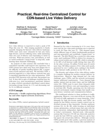
VOGEL Centralized Lubrication Systems1 0002 USSystems, Symbols, Functions, Planning, InstallationA VOGEL centralized lubrication system performs the task ofsupplying individual lube points or groups of points withvarying amounts of exactly metered lubricant from onecentral location to meet their different needs.Oil and grease of NLGI grades 000 to 2 are used as thelubricant.Care taken during the installation, start up and maintenance ofthe central lubrication system will help to enhance the operatingreadiness and life of your machines. The central lubricationsystem must be given the same attention as all the other sophi sticated equipment on a machine.The many years of experience we have had in the field of centrallubrication technology for machines and systems will help yousolve the problems you encounter when planning and using suchinstallations.The members of our field service will be pleased to advise you.Centralized lubrication systems, an overview(based on DIN ISO 1219 and/or DIN 24 271)TypesCentralized lubrication systemsCirculating lubrication systemsTotal loss systemsSystemsLubricantoilLubricantsSingle line systemsoilFett(NLGI grades 000 to 1)oilProgressive feeder systemsoilFett(NLGI grades 000 to 2)oilDual line systemsoilgrease(NLGI grades 000 to 2)oilMulti line systemsoilgrease(NLGI grades 000 to 2)oilRestrictor systemsoilOil air systemsoilwww.vogelag.com
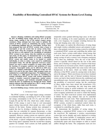
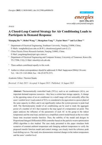
VOGEL Centralized Lubrication Systems1 0000 USSingle line total loss lubrication systemFor relatively small, consumption oriented amounts of oil perlube point and intermittent oil delivery.GGGThe oil delivery units are manually, mechanically, hydraulicallyor pneumatically actuated piston pumps or intermittently oper ated gear pumps.The lubricant is metered out by piston distributors installed inthe tubing system. Exchangeable metering nipples on the dis tributors make it possible to supply every lube point with therequisite amount of lubricant per stroke or pump work cycle.The metered quantities range from 0.01 to 1.5 ccm per lubri cation pulse and lube point. The amount of lubricant to be fedto the lube points can also be influenced with the number oflubrication pulses.An oil return line from the lube point to the oil reservoir is notrequired on total loss lubrication systems.The basic layout of a single line total loss lubrication systemis always the same:pump, piston distributormain line (connection: pump – distributor),secondary line (connection: distributor – lube point).See example of a system, diagram 2.Both groups of pumps, piston and gear pumps, have a hydraulicpressure relief device that lowers the pressure of the lubricantin the main line (10 45 bars) to a residual pressure ( 0.4 bars)via a relief valve after the lubricant has been delivered. Thisprocess causes the distributors to reverse.Piston distributors meter out and distributethe oil delivered by the pump (e.g. oil orgrease of NLGI grades 000 or 00). The quanti ties of lubricant for the individual lube pointsare determined by exchangeable meteringnipples. The metered quantity is shown on theindividual nipples.Four groups of distributors that differ in terms of metering rangesand sizes can be chosen from to comply with the amountsrequired and space available. A mixture of the different distribu tor groups can be used in one system.Because of their electric drive, gearpumps are especially well suited forautomatic systems with monitoring andsafety equipment; they can also be putto advantageous use on remote controlsystems operated by pushbutton.See example of system, diagram 1.Piston pumps have a limited deliveryvolume per stroke, as a result ofwhich there are limits on the meteredquantities and size of a system.Piston pumps are used in the form ofmanually, mechanically, hydraulicallyor pneumatically actuated pumps.Piston distributorsAutomatically operated systems also come with control andmonitoring units, pressure switches, float switches, indica tor lights.Gear pumpsPiston pumpsSee leaflets 1 1101 US, 1 1108 US, 1 1110 US, 1 1202 US, 1 1203 US,1 5001 USModel MFEExamples of systemsDiagram 1: Gear pump unit, model MFEFilterPressure gaugePiston distributorFiller couplingFloat switchVent filterSuction strainerPressure switch, max.Pressure switch, min.Diagram 2: Piston pump, pneum. actuated2
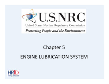
VOGEL Centralized Lubrication Systems1 0002 USPlanning, installation and maintenanceGGGGGDetermine the number of lube points.Assume the amounts of oil required per lube point and thetotal amount of oil required per stroke (with piston pumps) orwork cycle (with gear pumps).Select the distributors in accordance with the metering rangeand space available. A distinction must be made between oil only distributors and those also suitable for fluid grease.Choose pumps in accordance with the type of actuation andsystem capacity. *)Determine the type of control for automatic systems (time orload dependent) and any monitoring system that might berequired.When installing a system, lay out the main lines and distributorsin such a way that air in the system can escape on its own viathe lube points.To do so, install the distributors at suitable places and at the endof the system so that the outlets to the lube points (Fig. A) pointupward.If possible, lay the main line from the pump to the distributors sothat it rises.AIf lines have to be laid to distributors beneath them, proceed inaccordance with Fig. B or C.lube pointsecondary linesocket uniondouble cone sleeveDo not connect the secondary line (connection: distributor – lubepoint) to the lube points until bubble free oil emerges from thetubing after repeated actuation of the pump. It may be necessaryto prefill long secondary lines.If one secondary line is blocked or broken, that will have no influ ence on the remaining lube points.When the lever is pulled on systems witha manually actuated piston pump, itmeets with resistance (oil cushion). Thelever must not be pulled all the way to thehard cam stop but must be briefly held inplace at the pressure point. This ensuresall the distributors are completely filled(cf. system capacity). If a very small vol ume is involved, it may be possible tomove the lever only a short distance;excessive force should not be used.The layout of the distributors and lines isgood if the system bleeds itself via the distributors while it isbeing filled by repeated actuation of the pump without havingto open the ends of the main line.*) System capacityWhen planning systems it must be remembered that the calcu lated capacity of the distributor system must not exceed 2/3 ofthe delivery rate per stroke or work cycle of a pump in order toensure the reserve required for the pressure build up in the sys tem.The system capacity is comprised of the following:total output of all distributors in the system, 25 % of this value, 1 cccm per meter of main line (expansion loss).BNotice!CCheck the resistance in the main line, particularly in regard to therelief process, when especially large and widely branched systemsare involved and when high viscosity oils are used.The considerations required for the planning must be confirmedwith a test setup if pure calculations do not lead to the goal.Every distributor outlet may be connected to only one lube point!The socket unions must be tightened but not overtightened! Maxi mum of 1 1/2 turns! (A hard stop cannot be felt since the doublecone sleeve and tube are slightly deformed when tightened.)All products from VOGEL may be used only for their intended purpose.If operating instructions are supplied together with the products, the provi sions and information therein of specific relevance to the equipment mustbe observed as well.In particular, we call your attention to the fact that hazardous materials ofany kind, especially the materials classified as hazardous by EC Directive67/548/EEC, Article 2, Par. 2, may only be filled into VOGEL centralizedlubrication systems and components and delivered and/or distributed withthe same after consultation with and written approval from VOGEL.All products manufactured by VOGEL are not approved for use in con junction with gases, liquefied gases, pressurized gases in solution and flu ids with a vapor pressure exceeding normal atmospheric pressure(1013 mbars) by more than 0.5 bar at their maximum permissibletemperature.3
VOGEL Centralized Lubrication Systems1 0000 USCirculating lubrication systemGWhen oil is distributed via restrictors and multi circuit pumps,the lube points are supplied with a continuous flow of oil inpreviously determined amounts. Progressive feeders, on theother hand, are pulsed. Different amounts of oil can be ad justed with progressive feeders by selecting different sizes offeeder sections.GAn oil return line from the lube point to the oil reservoir mustbe provided for in the case of circulating lubrication systems.For relatively large amounts of oil (also for heat dissipation)per lube point and continuous oil supply.GThe delivery units are gear, gerotor, piston and vane pumps.GThe lubricant is apportioned to the lube points via restrictortubes, metering valves, adjustable metering valve distributors,flow control valves, progressive feeders and multi circuit gearpumps, from which as many as 20 lines can be connecteddirectly (or via flow volume dividers) to the individual lubepoints.Circulating lubrication with single circuit gear pump unitOil distribution via metering valvesmanifoldCirculating lubrication with single circuit gear pump unitsmeteringvalveOil distribution via restrictor tubesadaptertee piecemanifoldrestrictor tubesrestrictor tubesBranches of lines established with teepieces, or manifolds with adapters.The more symmetrical the layout of thetubing network the more even the dis tribution of oil via the restrictor tubes.manifoldadapterTubes with the largest possible diametersshould be laid from the pump to the branch off points.When different amounts of oil are required by the individualpoints, the respective amount can be arrived at by changingthe length or diameter of the restrictor tubes.When an uneven distribution of lubricant is involved, the resist ance of the individual restrictor tubes must be adjusted byvarying the tube diameters and lengths so that they produce anequally large pressure loss among each other with different dis charge volumes. Since there are limits on the extent to whichtube diameters can be varied, the fine adjustment must be donevia the lengths, e.g. by installing them in bends or spirals.Systems with restrictor tubes are reliable in operation and notsensitive to dirt.Oil quantities per lube point approx. 0.2 230 ccm/min.Metering valves can be combined on mani manifoldfolds or screwed into the threads of theindividual lube points.A microfilter must be installed upstreamfrom the systems. Filters with replaceablecartridges, among others, are suitable. Ifmetering valvethe flow of oil is to be ensured even whena filter is clogged, it is possible to provide for a by pass protect ed by a safety valve.The pressure losses occurring in the tubing must always beknown when a system is designed.This pressure loss table will provide an impression of the influ ence various factors have.TubeOperatingPressure losses p [bars] per meter of tubingdesignation viscosityon externalof oilFlow rate Q [l/min]diam. x0.1 0.2 0.512.5469wall thickness [mm 2/s] 0.052.5 x 0.5321.93 3.86 7.71100 6.02 12.05 320 19.28 1000 4 x 0.73210032010000.21 0.43 0.85 2.14 4.270.67 1.33 2.67 6.67 2.14 4.27 8.54 6.67 13.35 6 x 90.270.872.720.220.682.186.810.44 1.09 1.74 2.62 3.921.36 3.41 5.45 8.17 12.264.36 10.90 17.44 13.62 30.090.300.940.080.240.752.350.150.471.514.710.38 0.60 0.90 1.361.18 1.88 2.82 4.243.77 6.02 9.04 13.5611.77 18.83 10 x 0.7321003201000 0.020.06 2.146.690.321.003.2110.0412 x 1321003201000 0.010.03 0.01 0.02 0.01 0.03 0.060.02 0.04 0.10 0.200.06 0.12 0.31 660.180.551.765.49Example1.2 l/min is be split up into0.2, 0,4 and 0.6 l/min.Oil viscosity 175 mm2/s(cf. pressure loss table at Q 0.2 I/min)For tubes4 x 0.7; 0.5 m long and Q 0.2 I/min, p 4.68 · 0.5 2.3 bars6 x 0.7; 2.4 m long and Q 0.4 I/min, p 0.48 · 2 · 2.4 2.3 bars6 x 0.7; 1.6 m long and Q 0.6 I/min, p 0.48 · 3 · 1.6 2.3 barsSee leaflet 1 5006 US 4
VOGEL Centralized Lubrication Systems1 0002 USCirculating lubrication with gerotor unitCirculating lubrication with multi circuit gear pump unitOil distribution via metering valve distributorsOil distribution via multi circuit pumpsThe flow rate per lube point is adjustable.Multi circuit gear pumps ensure an even distribution of oil,even in the case of varying back pressures.We make a distinction between:metering valve distributorsfor flow rates in the range of dropsquantity per outlet:0 10 ccm/minOne delivery circuit of the pump is assigned to each lube point.metering valve distributorsfor continuous flow ratequantity per outlet:10 1000 ccm/minor 10 2000 ccm/min2 to 20 delivery circuits per pump0.015 to 1.2 l/min per delivery circuitThe layout of the tubing system and the tubing resistance valuesare mostly of no significance for the distribution.filtersafety valveGroup lubrication makes it possible to lubricate and monitor groups of machines and production lines from one central location.The monitoring possibilities range from a simple pressure gauge display and flow indicator to pressure or flow dependent control andsignaling units as well as electronic monitoring of the lube points.Example of a system, schematic diagramfor a turn broaching machine with 41 lube points.Progressive feeders and piston distributors are combinedin one system here via 4/2 way valves.5
VOGEL Centralized Lubrication Systems1 0000 USProgressive feeder systemsDual line systemsCentral monitoring of all feeder outlets at low cost is easy in pro gressive feeder systems.Metered quantities of lubricant are fed progressively in predeter mined order from the feeders to the lube points either directly orvia a secondary downstream feeder. The lubricant does not leavethe respective feeder until the preceding one has discharged itsvolume. If a lube point does not accept any lubricant – regard less of the reason – or if a secondary feeder is blocked, theentire lubrication cycle is interrupted, which can be used to emita signal.Dual line systems are central lubrication systems with two mainlines. They are preferably used for grease, but they are alsosuitable for oil.Characteristic features:G Universal application in regard to mode of operation and lubri cants.G Central monitoring of functions of all feeders possible at lowcost. *G Rugged feeder design.G Low susceptibility to breakdowns due to fitted pistons withoutsprings or compressive seals.G Number of cycles: max. 200/min (this can be used to calculatethe maximum possible oil quantity per outlet in circulatinglubrication systems).G Exact apportioning of the lubricant, even if back pressureencountered at the lube points.G Maximum number of lube points about 100; several hundredin the case of ring circuit systems with in line meteringpumps.G Pressures:30 100 bars in the case of circulating oil systems;max. 250 bars in the case of grease systems.G The price of progressive feeder systems is between that ofsingle line systems and dual line (grease) systems.The planning, especially any changes in the metered quantities ofindividual lube points at a later date or changes in the number oflube points, requires more time and effort than with single lineand dual line systems.All the distributors of a system are pressurized at the same time.That means lower pressure losses in comparison toprogressive feeders. Nor are the pistons spring loaded as withsingle line systems. Instead, the “reset” of the delivery piston issimultaneously the 2nd delivery stroke, which takes place at fullpump pressure. That is why this system is especially suitable forextended systems and more viscous types of grease. Assemblieswith or without compressive seals are available for light andheavy duty operating conditions.Characteristic features:GGGGGGGGGGGGFor systems operated in rough conditions.300 to 1000 lube points or more!Length of main line 100 meters or more; depends onconsistency of the lubricant.Distribution points can be easily added and removed.Metered quantities are easy to change.Easy to plan.Complicated due to double main line.Suitable for all oils and grease up to NLGI grade 2.Exact apportioning of lubricant.Can be combined with progressive feeders.Reversing units for change of main line, with hydraulic or elec trical actuation.Range of pumps similar to that of progressive systems,but pressure is much higher.Dual line system* With single line and dual line systems only central monitoring of themain line is possible, including individual monitoring of any number ofselected lube points.cycle switchprogressivefeederSystem with progressive feedersOne sensor, proximity switchor microswitch monitors thefunction of all feeders.dual line distributormasterfeedersecondaryfeedersmain line 1main line 2pressure gaugereversing valvecomplete with microswitch2nd secondary feeder(possible with oil only)filterpumppumpsafety valveSee leaflet 1 0107 1 USsafety valveSee leaflet 1 0012 US6
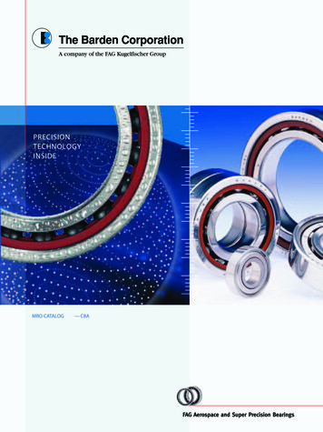
VOGEL Centralized Lubrication Systems1 0002 USHydrostatic LubricationSystem b) one pump circuit per recess(multi circuit pump system)In the case of hydrostatic bearings the oil pressure conforming tothe carrying force is produced in pumps outside the bearings,the oil being fed under this pressure to the recesses, from whichit flows out through the bearing gap.This system has a relatively good curve, and the costs arewithin reasonable limits, which is why this system is chosen mostoften.Three systems with different characteristics are available:a) restrictor systemb) one pump delivery circuit per recess(multi circuit pump system)c) diaphragm restrictorsThe lower the delivery rate per circuit the lower the oil viscosity,and the greater the pump pressure the more the delivery rates ofthe circuits differ from each other.The difference in pressure in a multi circuit pump can be limitedby using a priming pump, which benefits the evenness of the oilflow.This sequence also corresponds to the stiffness of the bearingassembly.Diagramideal curvea) restrictor systemb) one deliverrycircuit per recessflow ratec) diaphragmrestrictorThe total output of the multi circuit pump and the requisiterecess pressure per delivery circuit, with due consideration givento the permissible difference in pressure, determines the selec tion of this priming pump.The recess pressure can be kept within the desired limits via therecess size, and a medium viscosity oil should be striven for,with the exception of a few special tasks.In the case of bearing assemblies that are subject to greatfluctuations in pressure it is possible for the priming pressure tobe adjusted to the respective pressure of a characteristic recesswith the help of a proportioning pressure valve.bearing loadThe diagram shows the characteristic flow curves of the threesystems. If there is to be no change in the bearing's oil gap whenthe load on the bearing increases, the oil flow must rise in pro portion to the load. That is expressed by the "ideal curve". Thethree technically possible systems deviate more or less from thiscurve. The bearing stiffness therefore drops when the deviationincreases.load (kg)stiffness ——————————gap change (µm)Generally, the oil supply system and pumps will be selected at thesame time as the bearings are calculated. In this respect it isnecessary to take the efficiency of the pumps into account as well.pressurerecessesslideway bearingshaft bearingpressure recessesThe priming pump supplies the multi circuitpump with oil.In the starting phase the proportioning pres sure valve keeps pressure P1 at approx. 2.5bars. The surplus oil is returned via R.oilreturnIf pressure P2 rises, priming pressure P1 isalso accordingly increased via the valve sothat the difference in pressure is keptroughly constant. The difference in pressurebetween P2 and P1 should not exceed 4 7bars, depending on the delivery rate of thedistributing pump.multi circuit pumpleakage oilfilterpriming pumpproportioning pressure valvemax. pressure 100 barsTube connections:From P1 to P, from P2 (a “characteristic”pressure recess) to Z and from R to the oilreservoir.safety valvestrainertwenty circuit unitwith built inpriming pumpSee leaflet 1 1204 US7
VOGEL Centralized Lubrication Systems1 0000 USMinimal quantity lubricationMinimal quantity metering systems for the lubrication of tools, oiling of joined parts, spraying or wetting of surfacesand the lubrication of chains.These systems can also be put to successful use for the oiling of compressed air used in pneumatic drives, like cylin ders the lubrication of which often poses problems in layouts with a large number of branch lines.The aforementioned tasks are very different. Nevertheless, it is almost always possible to find an optimum solution withthe existing components.The following are available:Injection oilers, 1 and 3 way (can be coupled in groups)Injection oiler with reservoir(see leaflet 1 5012 4 US)Injection oilerwith reservoirSingle line central lubrication systems with piston distributorsMixing heads without integrated metering unit(see leaflet 1 5012 5 US)Mixing valves without integrated metering unitMixing valves with integrated metering unit(see leaflet 1 5012 5 US)VECTOLUB Minimal Quantity Lubricationfor chains, cutting tools and dies(see leaflet 1 5012 2 US)lubricant reservoirhousingpressure control valvepressuregaugepulse generatorair intake filterspray blockvariousspray nozzlesExample of a system8
VOGEL Centralized Lubrication Systems1 0002 USPressure curves in the main lines of central lubrication systemspressureSingle line system with single line prelubrication distributortime(to DIN 24 271)Due to the lubricant pressure resulting from the pressure build upin the main line, a metered quantity of lubricant is briefly fed(directly) from the single line prelubrication distributor to the lubepoint after overcoming the resistance that can occur all the wayto the friction point. When the pressure of the system’s safetyvalve is reached, the pressure does not continue to rise while thepump is still running. The pressure relief time (B) begins whenthe pump stops. During the pressure relief time (B) the pressurein the main line is reduced to a residual pressure with the help ofa pressure relief valve, a metered amount of lubricant for thenext lubrication cycle being readied in the single line distributorby spring force. The interval at which one lubrication cycle fol lows the next is determined by the interval time (C), which can bepreselected with, for example, the help of a timer.A lubrication cycle timeB pressure relief timeC interval timeD work cycle timeB CA C DSingle line system with single line relubrication distributorpressureWhen the pump is running, a metered amount of lubricant isreadied in the single line relubrication distributor, this quantitysubsequently being passed on (indirectly) to the lube point by theforce of a pressure spring in the distributor when the pressure relief time (B) commences. The discharge of lubricant to the lubepoint takes a while, depending on the resistance encountered upto the friction point.timepressureDual line systemtime(1st main line)time(2nd main line)A lubrication cycle timeB pressure relief timeC interval timeB CD work cycle timeA DThe lube points of a dual line system are divided up into twogroups, one of them being fed with lubricant during partial lubri cation cycle A1, the other during partial lubrication cycle A2.A dual line distributor is connected to two main lines, feeding alube point of the first group via the first secondary line and a lubepoint of the second group via the second secondary line.The pump only runs during partial lubrication time A1 or A2 andis stopped, for example, by a pressure switch. The redirection ofthe flow of lubricant to the other respective main line is done witha reversing valve.The respective main line is relieved of pressure to a certainextent during partial interval times C1 or C2. It is possible for thecycles in the two main lines to overlap. In extreme cases cycleA2 can follow directly on cycle A1.ACDA1A2pressureProgressive feeder system lubrication cycle timeB1 pressure relief timeinterval timeB2 pressure relief timework cycle timeC1 partial interval timepartial lubrication cycle time C2 partial interval timepartial lubrication cycle timeC 0C C1 C2A A1 A2A C DThe lubrication cycle time (A) in a progressive feeder system isidentical with the pump running time and is limited by the factthat all the lube points of a system must be supplied at leastonce with the specified amount of lubricant. The pressure in themain and secondary lines is relieved to a certain extent duringthe interval time.timeA lubrication cycle timeC interval timeD work cycle timeA C DMetering valve system and multi line systempressureAs long as the pump is running, all the lube points of a systemare supplied more or less continuously with lubricant.The running time of the pump is called the lubrication time.The lubrication time and interval time are combined to form awork cycle. It is, however, only sensible to speak of a work cyclewhen the central lubrication system is started and stopped sev eral times in the course of a workday (or shift), e.g. by a timer.Otherwise, continuous operation is involved.timeC interval timeD work cycle timeE lubrication time9
VOGEL Centralized Lubrication Systems1 0000 USDrawings showing the function and basic design of some equipmentMetering valvesGroup VDPiston distributorsecondary line0.2 to 230 ccm/minRelatively small amountsof oil are fed to thelube points withmetering valves.strokemetering nipplemetered amountShort bores and smalldiameters are easilyclogged. This is why along thread with thelargest possiblerectangular profile hasbeen selected.changeover valvemain lineSee leaflet 1 5006 USGroupGroupGroupGroup320:340:350:390:0.01 to 0.16 ccm/stroke0.01 to 0.16 ccm/stroke0.1 to 0.6 ccm/stroke0.2 to 1.5 ccm/strokeFunction:The quantity of oil intended for the lubepoint is located in front of the piston.When the central lubrication pump startsdelivering oil, the piston moves, and the oilin front of it is delivered at the pump pres sure (10 45 bars) in the direction of thelube point. After the pressure in the mainline is relieved, the distributor piston re turns to its initial position, allowing a quan tity of oil to flow into the metering chamberonce again via its changeover valve.See leaflet 1 5001 USProgressive feederThe lubricant supplied is divided up in the predetermined ratiovia the specified distributor outlets. The piston diameter and pis ton travel determine the output.A piston cannot deliver its lubricant until the preceding pistonhas discharged its quantity of lubricant.lubricantinletlubricantinletFig. 1Fig. 2In Fig. 1 piston side 4 is under pump pressure, piston side 1 hasdelivered to outlet 1a. The connection between the main line andpiston side 5 has opened due to the motion of piston 1/4.In Fig. 2 piston side 5 is pressurized, and piston side 2 is deliv ering via outlet 2a. Piston side 6 is the next to be pressurized,etc. See leaflet 1 0107 USGerotor pumpMulti circuit pump1 m suction headsmooth running,medium pressuresfor 2, 4, 5, 8, 10, 20 circuitssuction sideSee leaflet. 1 1204 USFlow rate between0.015 and 1.2 I/minper circuitpressure side10
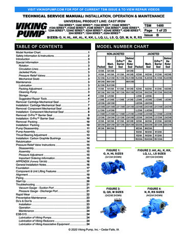
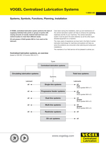
VOGEL Centralized Lubrication Systems1 0002 USViscosity / temperature relationship of oils with different basic viscositiesThe curves are based on a viscosity index of Vl 95, whichroughly corresponds to customary mineral oil. The viscosity indexdescribes the slope of the curve and thus the viscosity/tempera ture ratio at temperatures other than 40 C.The curves appear to be straight lines because a logarithmic scalewas chosen for the ordinates. It is therefore easy to determine theslope of the curves with the help of 2 measuring points.20 00014 00010 00070005 00040003000Viscosity class *)ISO VGoil classification2 0003, 10 .32, 100 .320 .1000 .1 5001 000700spindle oilsstandard machine oilsmedium heavy machine oilsgear oils, etc.*) The values correspond to the mid pointviscosity at 40 C in mm2/s500400300VGO 0IS 00120015003210001090807060503240301025201531098 Kinematic viscosity [mm2/s]7654.543.532.82.6 30 25 20 15 10 50510 15 20 25 30 35 40 45 50 55 60 65 70 75 80 85 90 95 100Temperature [ C]Please note: the change in the viscosity of oil is incomparablygreater at lower temperatures than in higher temperature ranges.For example, there are the following changes in viscosity for anoil with a rated viscosity of 100 in different temperature ranges atthe same temperature difference:at 80 C 18 mm2/sat 10 C 875 mm2/svs.at 75 C 21 mm2/schange of3 mm2/sat 5 C 1450 mm2/schange of575 mm2/s11
VOGEL Centralized Lubrication Systems1 0002 US12Graphic symbols for the representation of central lubrication systems in technical drawings(Excerpt of examples from our production program. Further symbols can be found on the Internet at: www.vogelag.com)GeneralDistributorsLube pointThis where lubricant isfed to the friction point.Piston distributor(single line distributor)Example: 353 (3 way)See leaflet 1 5001 USPumpsMetering valve distributor,adjustableExample: 242 034.00 (3 way)See leaflet 1 5006 USPiston pump, pneumaticallyactuated, with greasereservoirExample: PF 289See leaflet 1 0015 USProgres
VOGEL Centralized Lubrication Systems 10002US www.vogelag.com Systems, Symbols, Functions, Planning, Installation A VOGEL centralized lubrication system performs the task of supplying individual lube points or groups of points with varying amounts of exactly metered lubricant from one central location to meet their different needs.