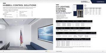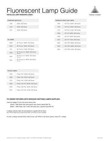
Transcription
Fluorescent dimming systemsTechnical Guide
Fluorescent dimming systemsTechnical GuideInnovation and quality from the worldleader in lighting controlsLutron invented the world’s first electronic dimming ballast over 30 yearsago. Lutron continues to lead the industry with innovative and energy-savingfluorescent dimming options, offering an extensive selection of ballastsand controls, and providing complete fluorescent dimming tron fluorescent dimming ballastsHow it worksLamp informationBallast factorBallast efficacy factorPower factorTotal harmonic distortionBallast lifetimeMounting and groundingSockets and lampholdersLamp wiring diagramsBallast control typesEcoSystem ballastsEmergency backup ballastBallast troubleshootingInstallation best practicesAppendix A: Application noteAppendix B: Application noteGlossaryFor ballast model numbersand control selections, pleasesee P/N 367-2248 REV A.This guide is designed to be a complete resource for all technical aspectsof Lutron fluorescent dimming systems. The technical guide will reviewthe basics of fluorescent lamps and dimming ballasts, including functionalprinciples, lamp varieties, ballast factor, and lifetime expectations. Installationtopics such as ballast mounting, grounding, lamp mounting height, wiringschemes, and troubleshooting will also be covered in detail.To search online for theballast that best fits yourproject, visit the updatedBallast Selection Tool sLutron World Headquarters: 1.610.282.3800 Technical Support: 1.800.523.9466 24 hours/7 days (US/CAN)Lutron 01
For a complete listing of model numbers, see the Fluorescent ballasts and LED drivers Selection Guideor consult product pages on www.lutron.comLutron fluorescent dimming ballastsFluorescent ballastsEcoSystem H-SeriesballastsEcoSystem H-SeriesballastsGlobal modelsHi-lume 3D ballastsCompatible Lamp Types and Wattages T8 linear and U-bent: 17 W, 25 W, 32 W T5 HO linear: 24 W, 39 W, 54 W T5 linear: 14 W, 21 W, 28 W EcoSystem ballasts EcoSystem compactballastsHi-lume ballasts T8 linear: 32W, 36 WT5 HO linear: 54 WT5 linear: 14 W, 28 WT8 linear and U-bent: 17 W, 25 W, 32 W, 40 WT5 HO linear: 24 W, 39 W, 54 W, 80 WT5 linear: 14 W, 21 W, 28 WT5 twin-tube: 36 W, 40 W, 50 WT8 linear and U-bent: 17 W, 25 W 32 WT8 linear Reduced-Wattage: 25 W, 28 W, 30 WT5 HO linear: 24 W, 39 W, 54 WT5 linear: 14 W, 21 W, 28 W, 35 WT5 twin-tube: 36 W, 39 W, 40 W, 50 W, 55 WT5 twin-tube Reduced-Wattage: 25 WT4 4-pin quad-tube CFL: 18 W, 26 WT4 4-pin triple-tube CFL: 26 W, 32 W, 42 WT5 HO linear: 24 W, 39 W, 54 WT4 4-pin triple-tube CFL: 26 W, 32 WInput Voltage UNV: 120 V, 220/240 V,277 V @ 50/60 Hz 127–220 V INMETRO @ 50/60 Hz 220–240 V CE @ 50/60 Hz 220–240 V CCC @ 50/60 Hz 347 V @ 60 Hz UNV: 120 V, 220/240 V,277 V @ 50/60 HzUNV: 120 V, 220/240 V,277 V @ 50/60 HzControl Options EcoSystem digital linkM-case UNV: 120 V, 220/240 V,277 V @ 50/60 Hz120 V, 277 V @ 60 Hz EcoSystem digital link 3-wire EcoSystem digital link 3-wire controlLow-voltage wallboxcontrols occupancy anddaylight sensors EcoSystem digital link 3-wire C-caseJ-case T8 linear and U-bent: 25 W, 32 WT4 4-pin quad-tube CFL: 18 W, 26 WT4 4-pin triple-tube CFL: 18 W, 26 W, 32 W 120 V @ 60 Hz Integral SensorConnectionsNo1% for T5 and T5 HO1%No0.7% for T8NoC-case(for 347 V only)G-case1% for T5 and T5 HO5% for T5 twin-tubeand T5 HO 80 W10%Yes5%No1%No5%NoG-caseK-case3-wireA-caseTu-Wire ballastsG-caseEcoSystem digital linkM-case Available Case TypesLow-enddimming level0.7% for T8C-caseTu-Wire (fluorescent)A-caseB-caseC-case02 Lutronwww.lutron.com/ballastsLutron World Headquarters: 1.610.282.3800 Technical Support: 1.800.523.9466 24 hours/7 days (US/CAN)Lutron 03
How it worksLamp informationHow do fluorescent lamps work?Lamp typeA linear fluorescent lamp consists of a glass tubecontaining low pressure mercury vapor with a tungstenfilament at each end. Ultraviolet (UV) light is producedby striking an arc across the lamp from one filamentto the other, causing the gas to glow. The amountof current passing through the lamp determinesthe light output. The UV light is converted tovisible light by a thin coating of phosphor onthe inside of the glass. U-bent, twin tube andcompact fluorescent lamps are simply linearlamps with a varying number of bends.Lutron offers dimming ballasts for everypopular lamp type:CompactLutron dimming ballasts for compact lamps areoffered in quad tube and triple tube. Quad tubelamps appear to have two or four tubes, whiletriple tube lamps appear to have three. Theymount in 4-pin rapid-start sockets.LinearLinear lamps are straight lamps with pins at both ends.Lutron dimming ballasts work only with rapid-startlamps, which will have two pins at either end.Excitation of Phosphor Coating (Visible Light)UV Light EmissionArcFilamentHow does Lutron dim fluorescent lamps?Lutron ballasts adjust the current passing throughthe lamp to allow the user to control the light level.As part of the dimming process, it is importantto keep the filaments heated by passing a currentthrough them. Instant-start ballasts do not provideheat to these filaments and therefore can usesockets that connect the two filament pins together.All Lutron ballasts are rapid-start-type, whichprovide supplemental heat to the filaments.It is therefore important that these two pinsare not shorted together in the socket. Rapidstart sockets which keep these pin connectionsseparate, must be used with Lutron ballasts.Using instant-start sockets with a Lutron ballastmay cause permanent damage to the ballast,and will prevent proper operation.Lamp VoltageArc CurrentFilamentCurrentFilamentBallastBlue Leadswww.lutron.com/ballastsLutron World Headquarters: 1.610.282.3800 T5 Twin TubeLutron also offers ballasts for the T5 twin tubelamps. T5 twin tube lamps use a locking-type4-pin rapid-start twin tube socket.For selection information on our entire lineof ballasts and controls for different lamptypes, please see the Fluorescent DimmingSystems Selection Guide (P/N 366-002),visit www.lutron.com/ballast, or contactthe toll-free Lutron Technical SupportCenter at 1.800.523.9466.Reduced WattageReduced wattage lamps are designed to saveenergy through simply relamping from theirstandard wattage equivalents. Lutron offersdimming ballasts specifically designed to workwith some reduced wattage lamps.Lamp seasoning and lifetime Lamp life of fluorescent lamps is defined asthe time for which the lamp can operate withinits performance specification, i.e. produce thespecified light output and strike within specification.Dimming fluorescent lampswithout seasoning can reduce performanceand lamp lifetime. Why keep the lamps at full intensitybefore dimming? New fluorescent lamps can have impuritiesin them that lamp manufacturers cannoteliminate completely.Ways to Obtain Seasoned Lamps Operate new lamps continuously (timeperiod might include a weekend or holiday) Remove lamps with over 100 hours of usefrom another (non-dimmed) area; re-installin dimming area Use a lamp burn-in station to build aninventory of properly seasoned lamps Contact the lamp manufacturer for theirrecommendations on lamp seasoning. As a generalguideline, NEMA recommends 12 hoursof operation at full intensity before dimming.Red Leads04 LutronU-BentU-bent lamps have many of the same propertiesas linear lamps and are usually offered in the samesizes, except they are bent in a “U” shape. Lutrondimming ballasts for linear lamps will often controla U-bent of the same size and wattage. See NEMA LSD 23-2010 “Recommended Practice—Lamp Seasoning for Fluorescent Dimming Systems.”Technical Support: 1.800.523.9466 24 hours/7 days (US/CAN)Lutron 05
Ballast factorBallast efficacy factorOverviewOverviewBallast factor (BF), also referred to as relativelight output (RLO), is a measure of the lightoutput of a fluorescent lamp on a particularballast expressed as a percentage of its lightoutput on a standard reference ballast. BFis not a measure of ballast efficiency, sincethere are ballasts that produce both lowerand higher outputs than reference ballasts.Actual Lumen Output Reference Lumen Output Ballast FactorBallast efficacy factor (BEF) is the ratio of BFto the input power being supplied to the ballast.BEF considers both light output and correlatedpower consumption of a lamp-ballast system,allowing an effective comparison betweendifferent ballasts.BEF B allast Factor (%)Input Power (W)BF is sometimes thought to reflect the energyefficiency of the ballast. That is incorrectbecause BF only describes the relative lightoutput of a lamp-ballast combination anddoes not consider the power that the ballastis consuming. Hence if Ballast A andBallast B have the same BF but Ballast Ahas a higher power consumption, then it isless efficient than Ballast B.Example:BEF is the only objective method to comparethe performance between different ballasts.BF is the relative light output of a lamp on theballast and the input power in watts is theballast energy consumption. Therefore BEFis a quantity that relates the lamp light outputto the ballast power usage. BEF can then beused to calculate the lumens per watt (lm/W)of the lighting system.Example:Range of BFIn the electronic fluorescent ballast industry,BF ranges from 0.7–1.2. Therefore for any lamp,there are ballasts available that are designedto provide anywhere from 70% to 120% lightoutput of a reference. Ballast factors of allLutron ballasts are indicated on the respectivespecification sheets.Need for BF dataBF is important for fluorescent lighting designand specification as it helps to calculate thetotal lumen output of the lamps.Actual lumen output 2,400 lm 0.9 2,160 lmWhen doing lumens per watt (lm/W) calculationsto comply with watts per square foot (W/ft2)requirements in a region, the appropriate methodto compare ballast efficiency is by using BallastEfficacy Factor (BEF).BF of Lutron dimming ballastsThe ballast factor of Lutron linear fluorescentdimming ballasts is 0.85 or greater and forcompact fluorescent dimming ballasts it is 0.95or greater. See ballast specification sheet foravailable ballast factors for a given lamp.Typical installationConsider two 1 lamp ballasts for F32T8lamps. If the BF of the first is 0.90 and the BFof the second is 1.0, the second ballast is notnecessarily more efficient in producing light.Let the input power to the first lamp-ballastcombination be 34W. Let the input to thesecond lamp-ballast combination be 38W.First ballast BEF 0.9 BF 10034 W 2.65 BEFSecond ballast BEF 1.0 BF 10038 W 2.63 BEFThis illustrates that the ballast with the lowerBF may have greater efficacy and is thereforea lower energy usage product.Selecting CBFLutron enables customers to order ballasts with acustom ballast factor (CBF): factory-tuned ballastswith reduced ballast factors that achieve greaterenergy savings, meet lumen/ft2 specifications,and/or qualify for the highest levels for LEED.CBF is an option for all Lutron ballasts withEcoSystem control capability including: Hi-lume3D, EcoSystem, and EcoSystem H-Series, andcan be selected by utilizing the Ballast SelectionTool: www.lutron.com/BallastTool06 Lutronwww.lutron.com/ballastsLutron World Headquarters: 1.610.282.3800 Technical Support: 1.800.523.9466 24 hours/7 days (US/CAN)Lutron 07
Power factorTotal harmonic distortionOverviewOverviewPower factor measures how efficiently anelectrical device operates. In electronic ballasts,the input power is used to operate the ballastand provide power to the lamps. Power factorcompares the input power to the power actuallymade available to the ballast and lamps.Power Factor Input PowerLine Voltage Line CurrentPower factor is always a value less than one.The electrical design of a device determineswhether the input current and voltage areconverted to maximum power within the unit.If the current draw is in-phase with the voltage,the power utilization is maximized. When thetwo are out of phase, some amount of powercannot be efficiently converted. Ballast PowerFactor does not directly indicate the currentsupplied through the lamps, or how efficientlythe lamps produce light when operated ona particular ballast.Example:Power Factor 34.8277 V 0.13 A 0.96When line harmonics are present, the total currentis the summation of the fundamental frequencycurrent and the harmonic current. If the THD of anelectrical device is 20%, it introduces 20% of themagnitude of its input current back on the line asharmonics. If this device constitutes 10% of thetotal electric load in a building, then it contributesonly 2% to the total building THD. Codes andregulations require that total building THD notexceed 33%.Power factor correctionInductive loads generally have low power factorsand present day designs add sophisticatedcircuitry to achieve a power factor close to 1.The solution is called power factor correction(pfc) and ensures more efficient power.www.lutron.com/ballastsLine current is supplied to electrical equipmentat a fundamental frequency of 60Hz. Harmonicsto the fundamental current are integer multiplesof the fundamental frequency—the 2nd harmonicis at 120Hz, and the 3rd harmonic is at 180Hz,etc. Depending on the electrical design of theequipment, it can distort the input sine waveof the fundamental frequency and introduceharmonics on the power line.Why high THD is detrimentalSignificant harmonics are put back on the line ifthe load type is not linear and draws current fromthe line in short pulses. Harmonic currents do notprovide any power to the load, and flow in theneutral wire in a 3-phase system. Harmonicsup to 33% are allowed by ANSI.Range of ballast power factorHigh power factor products are rated greater than0.9. Lutron electronic dimming ballasts achievegreater than 0.95 power factor by efficient designand use of high-quality components. Utilitycompanies discourage low power factor devicesbecause of their high device losses.08 LutronTotal harmonic distortion (THD) is a measure of themagnitude of all the harmonics (distortions) of the inputcurrent expressed as a percentage of the fundamentalfrequency current of 60Hz. THD is an importantconsideration for electrical safety, but lighting typicallyaccounts for less than 30% of total building loadand 10% of a building’s overall THD.Lutron World Headquarters: 1.610.282.3800 THD may be a concern for 2-wire line-voltagedimming ballasts as the power wires carry thephase control dimming signal to the ballast.The current drawn by the 2-wire dimming ballastmimics the phase-control dimming signal andwill result in higher THD when dimmed.THD regulationsIn the early 1980s when there did not exist astandard for THD of electronics, some dimmingballasts would produce up to 100% THD whendimmed down to low light levels. There have beenmany design improvements since, and ANSIC82.11-1993 now specifies maximum 33% THDfor electronic ballasts.All Lutron ballasts have a THD rating of 20%or less. Hi-lume, Hi-lume 3D, and EcoSystemH-Series ballasts all have a THD ratingunder 10%.Technical Support: 1.800.523.9466 24 hours/7 days (US/CAN)Lutron 09
Ballast lifetimeMounting and groundingOverviewBallast mountingWhen fluorescent fixtures are dimmed down to80% of their maximum light output, the ballast hasto drive less current through the lamp. On average,dimming fluorescent lamps by 20% reduces theballast case temperature by up to 10ºC. Every10ºC reduction in ballast temperature doubles thelifetime of the electrolytic capacitors, and hencethe ballast.The operating temperature of a ballast can alsobe dramatically influenced by proper installation.Fixtures that mount a ballast to a metal surfaceand ensure full contact between the ballast and aconductive surface allow for proper heat sinkingof the ballast, and therefore lower operatingtemperatures and longer life.This should be verified by measuring thecalibration point in the intended fixture duringfixture design.Notes:1 Ballasts generate heat and MUST havea means to dissipate it.2 Ballasts MUST be mounted flushto the fixture in order to provide thebest heat transfer.3 Screws, knockouts, dimples, or featuresthat raise the ballast off the fixture(even slightly) are not acceptable asthese will impair the ballast’s abilityto dissipate heat.4 Avoid mounting the ballast on thefixture cover plate that holds the lamps.This mounting location is often thehottest point on the fixture.IBRATPOBallast MUST be mounted flushto the fixture along its entire lengthBallastOKMetal FixtureNoNoNoI ONCalibration point temperaturenot to exceed 65ºC. Maximumcase temperature 75ºC.C ALThe lifetime of a ballast is defined as the actualnumber of operating hours that can be achievedusing specified lamps operating within theirspecifications. Maximum lifetime is achieved notonly by using long-life components, but also bynot approaching the operating limits of thosecomponents. Ballast life is strongly correlatedwith the lifetime of the electrolytic capacitors,whose lifetime can be maximized by operatingthem at lower temperatures. Lutron ballasts aredesigned to operate for their rated lifetime underworst-case conditions; however, external factorssuch as dimming level and fixture mounting canhelp the ballast run cooler and last longer.INTGroundingFailure abilitycurveBoth the ballast and the fixture must be connectedto earth ground. Grounding the ballast to thefixture requires “star-type” screws, washersor nuts in order to penetrate the paint finishon the ballast. To ensure safety and performance,proper grounding is essential.Customer receivesLutron ballastBoth ends of the ballast must be attached to thefixture to ensure proper grounding. Running ballasts 10 C CoolerDOUBLES useful lifeNormalUsageUL and NEC require that the ballast and all partsof the luminaire be electronically grounded.Star-type washer designedto penetrate paint finishTimeLutron testand burn-in10 Lutronwww.lutron.com/ballastsLutron World Headquarters: 1.610.282.3800 Technical Support: 1.800.523.9466 24 hours/7 days (US/CAN)Lutron 11
Mounting and groundingSockets and lampholdersLamp mounting heightWhy are sockets important?Lamp TypeDistance from grounded surfaceT8 rapid-start socketT8 Linear0.125" – 0.75" (3.2 mm – 19.1 mm)T5 Linear0.125" – 0.50" (3.2 mm – 12.7 mm)T5 Twin Tube0.125" – 0.50" (3.2 mm – 12.7 mm)Mounting a fluorescent lamp too close to thegrounded metal will make the minimum intensitytoo low and may reduce lamp life. Lamps shouldnever touch metal surfaces. Mounting a fluorescentlamp too far away from the ground ed metal maymake the lamp flicker or not turn on at all.The listed mounting height ranges ensurethat dimming performance and lamp life ismaintained. It is important to make sure thatin installed fixtures these spacings do notchange over time.Fluorescent lampSocket with twomounting slotsFilamentLamp socket (side view)Fluorescent lampFlow of electricity for filament heatingMounting heightGrounded metalNote: If using 10% dimming ballasts, T5 twin-tubelamps can be mounted as close as 0.03125"(0.79 mm) and linear T5 and T8 lamps can bemounted at 0.0625" (1.59 mm).Dimming ballasts must connect to both lamppins to heat the lamp filaments—without heating,the lamp ends will become black and failpre ma ture ly (may take anywhere from a fewdays to several weeks). Additionally, poor lampto socket connections will result in poor dimmingor lamp striking.When installing Lutron ballasts, good lamppin-to-socket contact and correct wir ing arerequired to produce flicker-free dimming andensure long lamp life. For best filament contact,use only recommended sockets.High quality electrical lampholder connectionsare critical, especially in dimming fixtureassemblies.Lamp sockets must comply with IEC 60400.Inspect sockets for marks to ensure the socketcomplies with IEC 60400. Two examples of thesemarks are: E and Q. Sockets must have a Zmark as well. Use Rapid Start sockets.DO NOT use Instant Start sockets withLutron ballasts.See Appendix A (based on Lutron ApplicationNote 122) and NEMA Publication LSD 34-2006.Identifying rapid-start socketsTypical fixture mountedand wired ballastsSocket Lamp BallastRedTypical 2-lamp linear fixture withballast mounted in center troughRapid-start sockets are necessary because eachsocket must be able to accept two separate wiresfrom the ballast, and in some cases, two additionalwires from another socket. High quality rapid-startsockets have a good grip on lamp pins and makereliable connections with all wires. The backingmaterial of the socket should be the same as therest of the socket body, and should not deform withover-insertion of wires or repeated lamp changes.Rapid Start(Rotary Locking Variety)Rapid Start(Rotary Locking Variety)See Appendix A (based on Lutron ApplicationNote 122) and NEMA Publication LSD 34-2006.Ground planeBlueYellowRapid Start(Slide-In Variety)The back must NOT be made out of flexiblematerial (i.e. cardboard or paper)Instant Start(do not use)A jumper may have been installed for instant-startapplications. This jumper must be removed.WARNING: Using Lutron ballasts with instant-start sockets may dam age the ballasts.12 Lutronwww.lutron.com/ballastsLutron World Headquarters: 1.610.282.3800 Technical Support: 1.800.523.9466 24 hours/7 days (US/CAN)Lutron 13
Sockets and lampholdersSockets and lampholdersLinear fluorescent lampsCompact fluorescent lampsSockets for T8 Linear LampsThe sockets should be rotary locking type, withmetal contacts that make good, firm contact withthe lamp pins. The sockets may also be slide-inor knife-edge variety. The fixture must have agrounded metal surface near the lamp (see pg. 11).The sockets must be rapid-start type.Socket wiring for T8 LinearFor ballasts that control morethan one lamp, sockets wired tothe yellow or blue-with-whitestripe leads of the ballast mustbe wired in parallel, not in series.Sockets for T4 Compact LampsT4 compact sockets must be the 4-pin typeand must be used with 4-pin compact lamps.Instant-start sockets with 2-pin connectionscan only accept 2 wires and will not work.Sockets MUST be 4-pin rapid-start type.Socket wiring for T4 Compact 4-PinTypical 2-lamp installationRedBlueT8 LinearT8 U-BentSockets for T5 LampsThe sockets should be of the rotary locking type.The fixture must have a grounded metal surfacenear the lamp (see pg. 11). The sockets mustbe rapid-start type.Typically Yellow (or Blue with White Stripe) wiresNote: Yellows wired in parallelT4 Compact 4-PinSocket wiring for T5 linearFor ballasts that control morethan one lamp, sockets wiredto the yellow or blue-with-whitestripe leads of the ballastmust be wired in parallel,not in series.Sockets for T5 Twin Tube LampsUse only 4-pin “locking” sockets that hold thelamp in place. T5 twin tube lamps require properlamp support at the opposite end from the lampbase, to hold lamp pins in full contact withsocket. The sockets MUST be rapid-start type.Note: Yellowswired in parallelSocket Wiring for T5 Twin TubeTypical 2-lamp installationLocking mechanismprovides properlamp support.RedBlueNote: Yellowswired in parallelT5 LinearNote: Yellow wired in parallelT5 Twin Tube14 Lutronwww.lutron.com/ballastsLutron World Headquarters: 1.610.282.3800 Technical Support: 1.800.523.9466 24 hours/7 days (US/CAN)Lutron 15
Lamp wiring diagramsLamp wiring diagramsLinear 1-lampT5 twin-tube escent le in C-case, J-case, G-case and M-caseAvailable in G-case and J-caseLinear 2-lampT5 twin-tube 2-lampFluorescent LampFluorescent rescent LampLutronDimmingBallastYellowRedFluorescent LampAvailable in C-case, J-case, G-case and M-caseBlueYellowRedAvailable in G-case and J-caseLinear scent LampFluorescent LampT5 twin-tube scent LampYellowFluorescent LampRedFluorescent ueYellowBlue/WhiteRedAvailable in G-caseAvailable in G-caseNote: Lamp terminals accept only one 18 AWG wire.Ballast-to-lamp wire lead lengths must not exceed7 ft (2 m) for all wiring scenarios shown above.Note: Lamp terminals accept only one 18 AWG wire.Ballast-to-lamp wire lead lengths must not exceed3 ft (1 m) for all wiring scenarios shown above.16 Lutronwww.lutron.com/ballastsLutron World Headquarters: 1.610.282.3800 Fluorescent LampTechnical Support: 1.800.523.9466 24 hours/7 days (US/CAN)Fluorescent LampLutron 17
Lamp wiring diagramsBallast control typesT4 1-lampIn addition to offering ballasts with different low-end dimming levels,Lutron offers dimming ballasts with a variety of control options.LutronDimmingBallastRedBLUBLU4-PinLamp HolderREDREDBlueAvailable in K-case and A-caseNeutralConstant HotControl (E1)Control (E2)NeutralDimmed HotT4 2-lampLutronDimmingBallastSwitched HotRedBLUBLUYELYELREDRED4-PinLamp HolderEcoSystem digital link Models available: EcoSystem H-Series, EcoSystem, andHi-lume 3D ballastsDimming levels available: 1%, 5% and 10%The EcoSystem digital link is a wired communication technology thatfacilitates individual ballast addressing, connection of multiple controldevices, and control of ballasts individually or in groups. The digitalcommunication wires are polarity insensitive and may be wired in anytopology. They may be run with the line-voltage wiring (Class 1) orseparately from the line-voltage wiring (Class 2). The EcoSystem digitallink allows for the quick connection of devices and re-configurability.3-wireModels available: EcoSystem, Hi-lume and Hi-lume 3D ballastsDimming levels available: 1%, 5% and 10%3-wire control is a line-voltage phase-control dimming method. Alongwith Hot and Neutral, the dimming signal is communicated via a thirdwire called Dimmed Hot. All three wires are rated Class 1 and can berun within the same conduit. 3-wire control is stable over long wireruns, allows for maximum circuit loading, and is very easy to wire.YellowBlueAvailable in K-case and B-case4-PinLamp HolderNeutralDimmed Hot2-wireModels available: Tu-Wire ballastsDimming levels available: 5%2-wire control is a line-voltage phase-control dimming method.The ballast receives the dimming signal through the DimmedHot wire. Intended for small-scale retrofit applications, the 2-wirecontrol method is often the easiest way to implement dimmingin existing fluorescent fixtures.Note: Lamp terminals accept only one 18 AWG wire.Ballast-to-lamp wire lead lengths must not exceed3 ft (1 m) for all wiring scenarios shown above.18 Lutronwww.lutron.com/ballastsLutron World Headquarters: 1.610.282.3800 Technical Support: 1.800.523.9466 24 hours/7 days (US/CAN)Lutron 19
EcoSystem ballastsEcoSystem ballastsOverviewExample: sensor wiring connectionsLutron EcoSystem lighting control systems startwith one simple, but essential building block, theEcoSystem dimming ballast. EcoSystem digitallyaddressable dimming ballasts employ revolutionarytechnology allowing each device to listen, think,decide, remember, and react to its environment.A variety of sensors or wallstations can connectdirectly to the ballast to create an efficient lightingcontrol system, whether the system containsonly one ballast or up to 64 ballasts connectedtogether. Sensors and wallstations can also beconnected to the system through sensor modulesand control panels to allow for maximum flexibility.EcoSystem redefines fluorescent lighting controlas a cost-effective solution that is easy to design,install and maintain.EcoSystem ballasts are available for many voltagesand lamp types. If a ballast is not available fordirect control via the EcoSystem digital link, aLutron 3-wire dimming ballast can be connectedusing a Ballast Module. The system providescontinuous, flicker-free dimming from 100% to10%, 5% or 1% depending on lamp type. Lampscan be turned on at any dimmed level withoutfirst flashing to full brightness. The digital linkcontrol allows for re-zoning without rewiring, andmiswire protection is included in the EcoSystemlink. Components are 100% performance testedincluding burn-in before shipping, and includea 5-year limited warranty with field servicecommissioning (3-year warranty standard).G–case with daylight and IR sensorRedBlackWhiteYellowG–case with eBlackE1E2E1E2 20V 20V 20VCommonCommonCommonIROccDaylight 20V 20V 20VCommonCommonCommonIROccDaylightJ–case with occupancy sensorRedConnecting sensors and wallstationsBlackBlueTo connect a daylight sensor, occupant sensor,wallstation and/or infrared receiver, refer to theinstruction sheets provided with the devices.Diagrams for the Class 2 Sensor/Wallstationterminals are shown below.NOTE: The ballast accepts only one infraredinput connection from a daylight sensor,IR sensor or wallstation. 20VCommonIROccDaylightG-case Class 2 Sensor TerminalsJ-case Class 2 Sensor Terminals20 Lutronwww.lutron.com/ballastsLutron World Headquarters: 1.610.282.3800 Technical Support: 1.800.523.9466 24 hours/7 days (US/CAN)Lutron 21
Emergency backup ballastEmergency backup ballastOverviewIn commercial fluorescent applications, batterybackup ballasts are sometimes used for requiredemergency and egress lighting. Battery backupballasts provide one solution for addressingemergency lighting. These ballasts provide lighton a temporary basis when normal power has beeninterrupted. Some of the major manufacturers areBodine Emergency Lighting, Exide Technologies andIota Engineering.Emergency Ballast RecommendationsLutron fluorescent ballasts are designed toprovide lamps with a precise amount of voltageto ensure long lamp life, flicker-free performanceand lamp balance. The addition of an emergencyballast c
ago. Lutron continues to lead the industry with innovative and energy-saving fluorescent dimming options, offering an extensive selection of ballasts and controls, and providing complete fluorescent dimming solutions. This guide is designed to be a complete resource for all technical aspects of Lutron fluorescent dimming systems.