Transcription
Modular Water-CooledChillersInstallation, Operation,MaintenanceMS010XC, MS015XC, MS020XC, MS030XC,MS040XC, MS050XC, MS070XC, MS085XCStandard and Total Access Modules
This manual provides information on the proper installation, operation and maintenance requirements for Multistack watercooled modular chillers. Follow these instructions to help ensure that the chiller performs properly. Failure to follow these instructions can significantly affect the chiller’s performance and reliability and may adversely affect the equipment warranty.ContentsSafety Information.3Nameplate and Model Number Nomenclature.4Chiller Arrangement and Components, Standard and Total Access Modules.5-7General Data.8Shipping Information.9-10Clearances and Dimensions.11-16Piping, Flow Protection.17Pressure Relief Piping, Water Treatment Specifications, Pipe Flushing.18Module Assembly, Standard Modules.19-21Module Assembly, Total Access Modules.22Multiflush Assembly, Leak Testing.23Electrical Installation, Wiring, Electrical Data.24-28Frame and Enclosure Panel Installation.29Installation Checklist.30Start-Up Data ooting. 37Daily Log.38-39This Multistack installation and operation manual will assist in the proper installation and operation of Multistack modular chillers. Review thismanual carefully. The information and illustrations contained in this manual are generalized. Consult with a Multistack representative to address specificinstallation and operating details not covered in this manual. Good electrical and piping practices in accordance with all National and local codes must be followed. This equipment must not be installed near an open flame per local codes and ASHRAE specifications. Personnel servicing Multistack modular chillers must have, at minimum, a Class II EPA certification. Questions regarding the content of this manual and Multistack products should be directed to an authorized Multistack representative orto the Multistack Service Department at: (608) 366-2400 or via e-mail to info@multistack.comPlanning AheadTo ensure all warranties and a successful installation, a Factory Authorized Technician is required to perform start-up of the Multistack Chiller. If start-upis to be performed directly by Multistack, a minimum of two weeks notice is required. Please call the Multistack Service Department at (608) 366-2400 toschedule.Multistack has a policy of continual improvement and reserves the right to change product design, literature andspecifications without notice. 2016 Multistack2
Safety InformationThis manual includes warnings, cautions and notes.DANGER conveys serious hazards for injury or death.WARNING indicates risk of injury or death.CAUTION warns of possible injury or damage.NOTE calls out work practices that can result in optimal operations.Warnings, cautions and notes include:DANGER: To avoid the risk of electrical shock, personal injury or death, disconnect all electrical power to the unit before performing any maintenanceor service. The unit may have more than one electrical power supply. Assume all electrical wires are live, energized wires. Use lockout/tag outs.DANGER: Use extreme caution when working around electrical components, wiring and connections to avoid injury or death by electric shock.DANGER: Never remove a lockout from equipment unless you placed it there. Each person shall place his/her own lock/tag when required to isolatean energy source. Do not start any adjustment, service or repair without verifying that the tag/lock out switch or control cannot be by-passed or overridden. Verify that the locked-out switch or control cannot be overridden. Test the equipment to be certain that the locked-out switch is de-energizedand not simply malfunctioning. Press all start buttons to confirm that the equipment WILL NOT start. Confirm that the system being serviced orrepaired is the system that has been locked out. Before restarting equipment, verify all tools and other items have been removed, all machine guardsare in place, all electric systems are reconnected, and personnel are clear of equipment.DANGER: During installation, testing, servicing and troubleshooting this product, it may be necessary to work with live electrical components. Onlyqualified licensed electricians or other properly trained persons may perform these tasks. Failure to follow all electrical safety precautions can result indeath or serious injury. All HVAC equipment must be installed per the National Electric Code (NEC) and/or all applicable state/local codes.DANGER: Incorrect handling of HVAC equipment can result in explosions, electrical shock or fire, causing property damage, injury and/or fatality.DANGER: HVAC liquids and chemicals can be dangerous if used incorrectly or if spills or accidents occur. Handle detergents and solvents with care toavoid spills and burns.DANGER: Danger of explosion. Refrigerant cylinders can explode causing serious injury and/or death if not handled and stored properly.WARNING: Only qualified, licensed electricians with proper personal protection equipment should wire Multistack chillers. Injury or death my resultif not properly wired due to electric shock hazardWARNING: Danger of electrical shock. Many types of HVAC equipment have switches and regulators with electrical current on even when other partsof the equipment appear to be turned off. Main circuit breakers must be turned off before servicing equipment to avoid injury, fatality.WARNING: Be sure to use lifting slings with lifting capacity to safely handle unit weight. Consult the unit’s as-built submittal drawings for unitweight data.WARNING: If welding on chiller water connections, use proper electrical grounding to avoid damaging the compressors or chiller controls. Neverweld directly on the heat exchanger shells. Only an authorized ASME-certified repair agency may weld directly on ASME-certified shells. After welding, an “R” stamp is required.CAUTION: Working with HVAC equipment can be hazardous due to electricity, moving parts, chemicals, combustion and other hazards. Use safe workhabits including proper tools and personal protective equipment. Understand and heed all safety information, installation guidelines and operationand maintenance procedures.CAUTION: Pressurized application of cleaning substances or refrigerants must be done with the correct procedures to ensure the safety of techniciansand others, and avoid property damage.NOTE: Use correct tools for HVAC equipment installation, maintenance and adjustment. Use the correct tools to make tight connections without stripping threads or breaking screws and bolts. Use accurate refrigerant and electrical meters to properly maintain and diagnose HVAC equipment.3
Multistack Water-Cooled Modular ChillersTotal Access Modular ChillersMultistack invented the modular chiller. Multistack modularchillers are available in a wide range of capacities, and with twoindependent scroll compressors. Modules can be mix-matchedand combined to create up to 15-module arrays and 1,275 tons ofcooling capacity using environmentally friendly R-410A. Multistackmodular chillers can help owners qualify for USGBC LEED points andsignificant utility rebates. Multistack’s innovative modular designmakes adding more capacity as easy as purchasing and installingmore modules.With Total Access, heat exchangers are located on the outer edges ofthe chiller frame to provide easy serviceability with a small equipment room footprint. Total Access options include 10- through 85-tonmodular chillers.Unit NameplateThe chiller nameplate is located on the front of the control panel.Use the unit model number nomenclature to identify specificfeatures and options of an Multistack chiller module.Model Number NomenclatureMS050XC or N2H1W0AA-410ARefrigerantCondenser6Evaporator5AHRI Version - if applicableApplication4Module Number ( 1 - single, 2 - multiple)Voltage3Configuration2AHRI Certified (C - certified, N - Not certified)Compressor Type1Module Nominal Capacity (10 - 160 tons)SeriesB: Bristol, C: Trane Cornerstone, R: Bitzer Screw, S: Trane Scroll, T: Danfoss Turbocor, Z: Copeland scroll (old elec), X: Copeland Scroll (ZP), A: Copeland Scroll (ZR)1- Standard, 2- Total Access, 3 - Evap extended headers, 4 - Cond extended headers, 5 - Both extended headers, V - others3A - 208/3/60, L - 230/3/60, H - 460/3/60, C - 575/3/60, D - 200/3/50, E - 400/3/50, F - 380/3/60, S - 220/230/1/60, V - other4A - Air Cooled split, C - Single module temp controller, D - Cond unit, F - Fluid cooler (high temp),H - Heat recovery, R - Heat pump, W - Water cooled5A - Brazed SS, B - Brazed SMO, C- S&T copper, D - S&T cu-Ni, V - Other6A - Brazed SS, B - Brazed SMO, C- S&T copper, D - S&T cu-Ni, E - Double wall brazed, V - Other124
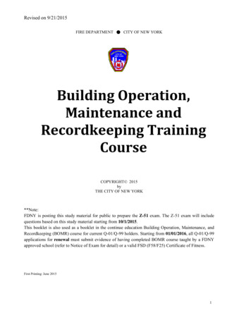
Standard Modular Chiller ArrangementScroll CompressorsHigh VoltagePanelHigh PressureTransducerLow hBuss BarDuctLeavingCondenserWaterHeaderLow PressureTransducerEntering ChilledWater /StrainersLiquid LineSight GlassLeaving ChilledWater HeaderCondenserExpansionValveTotal Access Modular Chiller ArrangementMultistack’s Total Access option makes maintenance and serviceability even easier by placing heatexchangers at the outside of the module frame. Manual isolation valves are factory-installed (TotalAccess units only) between the heat exchangers and water supply mains for heat exchanger isolation andremoval without the need to remove a module or shut down the entire chiller while allowing access to allserviceable components.High VoltagePanelIsolation/DisconnectSwitchLow VoltagePanelHigh PressureTransducerBuss BarDuctCondenserIsolationValveScroll CompressorsLow ionValveCondenser5
Chiller ComponentsMaster Control PanelEach chiller has a master control panel that can be mounted on top of anyof the module panels using provided knockouts. Sensors, cables and wiringconnect through the bottom of the master control. The master control boxincludes built-in terminal strip inputs for flow switches, start/stop signal, alarmoutput, and power phase monitor. As shipped, the Master Control also containsthe pLAN communication wire to be field installed by the start-up technician.Four temperature sensors and sensor wells are supplied by Multistack: enteringchilled water, leaving chilled water, entering condenser water, and leavingcondenser water. The sensors are to be installed in customer’s piping system.Master ControllerModule SlaveControllerModule Control Boards and Low Voltage PanelThe module control boards communicate individual module temperaturesand pressures to the master control. Each module has a switch labeled Auto/Off/ Manual. Normal operation is in the Auto mode. If there is a problem withthe master control, the selector switch can be changed to Manual to provideindividual module leaving chilled water temperature control that was pre-setat the master control.AUTO/OFF/MANUALSwitchModule High Voltage PanelThe high voltage panel contains each compressor’s contactor, circuit breaker,control relay and transformer. External to the panel is the single-module isolation switch to isolate the that module from high voltage supply power.Compressors, Sensors, Switches Standard modules use two scroll compressors with separate refrigerationcircuits. Each refrigerant circuit has a high pressure (HP) and low pressure (LP)transducer that sends pressure signals to the module slave controllerboard. Each compressor also includes an HP switch with a manual resetbutton. Transducers are a 0-5V ratiometric type. Compressors include oil level sight glasses. Oil level should be at 1/8 - 1/4full during operation. Each circuit has its own leaving chilled water temperature sensor andrefrigerant suction temperature sensor. Compressor crankcase heaters are not standard on Multistack MS chillermodules.Low VoltageCircuit BreakerLow VoltageTerminal StripsLow Voltage PanelA CompressorIsolation SwitchHigh VoltageControlCircuit BreakerControlRelay TransformerRelayB CompressorIsolationSwitchChilled and Condenser Water Connections 6Water connections to the chilled and condenser side are standard 6-inchgrooved pipes on MS010X through 070X, and 8-inch on MS085X units. The upper header on the chilled water side is entering water to themodule. The bottom header is chilled water leaving the module. Water entering the condenser is on the bottom. Water leaving the condenser is on top. The entering header on both the evaporator and condenser contains a 30mesh filter strainer to prevent debris from entering the brazed plate heatexchangers. This strainer should only be used as a final filter stage. Proper filtration before the module should be installed for easy access tocleaning, such as a ‘Y’ or a basket type of strainer.A CompressorContactorHigh Voltage PanelSingleCircuitBreakerB CompressorContactor
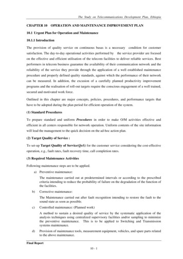
Expansion Valve, Subcooling, Liquid Line Sight Glass Each circuit on a module has a thermal expansion valve locatedbetween the water header pipes on the condenser side. Duringfactory run testing the valves are adjusted to maintain 10-12degrees superheat. Check the superheat periodically to maintainthis range. Subcooling should normally be in a 10-15 degreerange. No external subcooler is used. The liquid line sight glass shows green on the indicator bulb ifno moisture is present in the refrigerant circuit. Yellow indicatespotential moisture. Sight glasses should show full during normal operation. Flashing in the sight glass indicates possible under-charge of thecircuit. Refer to the unit nameplate for refrigerant charge information.ExpansionValvesSightGlassesExpansion Valves and Liquid Line Sight Glasses(Standard unit.)Power ActuatedButterfly ValveVariable Flow and Power Actuated Butterfly ValvesFor variable flow on the chilled or condenser water side, chiller modules must be ordered with power actuated butterfly valves.Note: The footprint of an array of standard modules will increase asthe valves add length. Total Access module footprint will not change.1. Multistack recommends controlling the chiller pumps to maintainpressure differential across the chiller, not the system. Controlbased on system pressure will provide erratic results.2. Chiller minimum flow bypass for the system can be programmedin the master controller.Optional Manual Isolation ValvesStandard modules are not supplied with isolation valves. Manual orelectrically actuated valves may be ordered as an option fromMultistack. Total Access modules are supplied with manual isolationvalves from the factory and may be upgraded to electrically actuatedvalves as an option. Multistack recommends exercising the isolationvalves as part of annual maintenance.Butterfly Valve Actuator for Variable Flow shown onstandard module with extended headers.Optional Hot Gas BypassAs an option, hot gas bypass valves (Sporlan HGBE-8) can be providedfor each circuit. The valve is adjustable from 75 to 150 psi with astandard setting of 120 psig. A screw on the pilot valve handles theadjustment. Turning clockwise increases the valve setting; counterclockwise rotation decreases the valve setting.Heat Exchanger Isolation Valves on TotalAccess Modular ChillerHot Gas Bypass Valve7
General Data 85XDry Weight (lbs. each)89135135146280293390419Normal Capacity (tons each)57.5Compressor Quantity/Module22101520253040222222Oil Charge (pints per compressor)3.56.96.96.99.59.513.313.3Compressor TypeScrollEvaporator (Brazed Plate)Brazed PlateWeight (lbs.)50707090180180220300Water Storage (gal.)1.01.61.62.25.55.57.310.1Circuit ity11111111Header System (gal.)777777714CondenserBrazed PlateWeight (lbs. each)508080100200200290340Water Storage (gal.)1.12.22.22.96.66.610.112.3Circuit ity11111111Header System (gal.)7777777146.56.56.51018202328Refrigerant TypeCharge (lbs./circuit)Number of 0.3Operating Weight (lbs.)1,490 (1,620)1,500 (1,630)1,510 (1,640)1,610 (1,740)1,790 (1,920)1,970 (2,100)2,060 ( 2,210 )2,350 (2,680)Shipping Weight (lbs.)1,330 (1,470)1,340 (1,480)1,350 (1,490)1,450 (1,590)1,630 (1,770)1,950 (1,990)1,890 ( 2,060)2,380 (2,630)Total Water Volume - gal./moduleNOTES: Figures in parentheses ( ) apply to Total Access configuration chillers.Add 75 lbs. per module if equipped with enclosure panels.Multistack has a policy of continual improvement and reserves the right to change product design, literature and specifications without notice.8
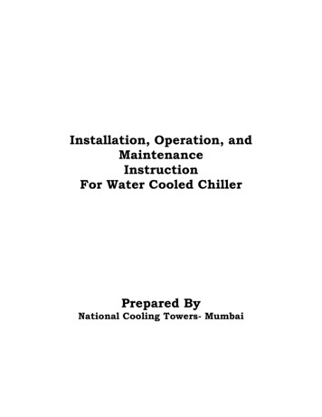
Module Shipment PackageNOTE: Before accepting delivery of the Multistack chiller, checkthe overall condition of the equipment for damage such as brokencopper lines, oil leaks, damaged controls and/or electrical componenthousing, or any major component torn loose from its mounting. Ifthe Multistack modular chiller is damaged during shipping by thetransportation company or its agent, the installing contractor MUSTpromptly file a claim with the transportation company and adviseMultistack. Any discrepancy or damage must be noted on the bill oflading.3542167Pallet #1 — Typical Cabinetry Package (Optional)1. Top Front Panel2. Bottom Front Panel3. Rear Panel/End Panel4. Side End Panel5. Master Controller Top Panel6. Frame Pieces7. Frame Connectors, Fasteners, Clips & Magnetic Tape118910Pallet #2 — Buss Connections8. Buss bar9. Buss bar insulation10. Ground strap11. Junction Box legMultistack has a policy of continual improvement and reserves the right to change product design, literature and specifications without notice.9
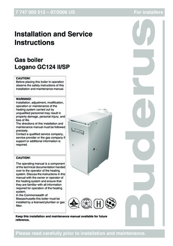
21181922203333372337363442392824412925263027Pallet #3 — Typical Piping & ElectricalPackage18. Master Controller*19. Junction Box20. Junction Box Cover21. Sensors / Cables22. Junction Box Connector (Throat)23. Power Phase Monitor24. Buss bar Connector25.26.27.28.29.30.3531Power Phase Monitor WireBuss bar Insulation OverlapPhase Monitor WireBuss bar End CapsDrain Valves & FittingsModule Joining Bolts31. End Cap for Multiflush system (upper)32. End Caps (evap)33. Couplings3934.35.36.37.38.39.40.41.42.40Multiflush pipeSolenoid for Multiflush systemPipe StubsEnd Cap Multiflush system (lower)Filter StopsPet Cock ValvesDrain Valves & FittingsSensor Wells30 Mesh Filter Strainer* May be shipped separately to sales office or job site.** Shipped inside #19 - Junction BoxMultistack has a policy of continual improvement and reserves the right to change product design, literature and specifications without notice.Moving Chiller ModulesCaution: Modules Are Top HeavyModule on Fork LiftModule on Pallet JackMultistack chiller modules MS010 through MS085 may be moved using a fork lift truck, pallet jack or similar equipment. Optional spreader bars for liftingand factory-installed wheels are available from Multistack. Contact your Multistack representative. For unit weights see the table on Page 8 and the jobspecific as-built submittal drawings.10
ClearancesDiagram shows typical dimensions and the recommended clearances around the modular chiller. There must be a minimum of six inches clearance over thetop of the chiller, including the top of master controller if installed on top of the module.For specific unit dimensions, refer to as-built submittal drawings.11
12A*Standardized drawing of sample customer installation** Enclosure panels are optional34”28”28”Total Access (MS070)Extended HeadersExtended HeadersB32”Total Access (MS010--050)C28”StandardWidth (A)Module Dimensions (No Panels)Standard Modules (Constant Flow Design)76 5/8”62 1/8”56”56”47 5/8”Depth (B)64”64”67”67”64”Height (C)
13A34”28”28”Total Access (MS070)Extended HeadersExtended HeadersB32”Total Access (MS010--050)C28”StandardWidth (A)Module Dimensions (No Panels)*Standardized drawing of sample customer installation**Enclosure panels are optionalVariable Flow Design for Chilled and Hot WaterStandard Modules with Extended Headers onEvaporators and Condensers76 5/8”62 1/8”56”56”47 5/8”Depth (B)64”64”67”67”64”Height (C)
14A34”28”28”Total Access (MS070)Extended HeadersExtended HeadersB32”Total Access (MS010--050)C28”StandardWidth (A)Module Dimensions (No Panels)*Standardized drawing of sample customer installation** Enclosure panels are optionalVariable Flow Design for Hot Water, Constant Flow for Chilled WaterStandard Modules with Extended Headers on Condensers76 5/8”62 1/8”56”56”47 5/8”Depth (B)64”64”67”67”64”Height (C)
15A*Standardized drawing of sample customer installation** Enclosure panels are optional32”34”28”28”Total Access (MS010--050)Total Access (MS070)Extended HeadersExtended HeadersC28”StandardWidth (A)BModule Dimensions (No Panels)76 5/8”62 1/8”56”56”47 5/8”Depth (B)Variable Flow Design for Chilled Water, Constant Flow for Condenser WaterStandard Modules with Extended Headers on Evaporators64”64”67”67”64”Height (C)
16A*Standardized drawing of sample customer installation** Enclosure panels are optional32”34”28”28”Total Access (MS010--050)Total Access (MS070)Extended HeadersExtended HeadersC28”StandardBWidth (A)Module Dimensions (No Panels)Total Access Modules With or Without Variable Flow76 5/8”62 1/8”56”56”47 5/8”Depth (B)64”64”67”67”64”Height (C)
CONDENSER SIDEEVAPORATOR SIDESensor Pockets, SensorsSupplied by Multistack,installed by others.Flow/DPSwitch IsolationPressureValvesTapsTo Cooling Toweror Fluid CoolerSensor Pockets, SensorsSupplied by Multistack,installed by others.PressureTapsChilled WaterPumpStrainerCHW InCW OutCW In3-WayBypass ValveCondenserPumpStrainerPressure IsolationTapsValvesCHW OutFlow/DPSwitchItems in This Area Includedwith ChillerRecommended PipingAll piping must be properly and adequately supported at coupling connections and suitable intervals along the piping runs. Hanger design mustprovide for the weight of fluids in the piping system when the chiller is in operation.Multistack modules are equipped with brazed plate heat exchangers made of 316 stainless steel. Multistack recommends use of a 30-mesh systemstrainer, Y-type basket or equal, in each condenser and evaporator inlet header.It is the installing contractor’s responsibility to make sure the water systems have been flushed and the strainers are clean and clear of debris beforestarting the chiller. Do not flush piping so as to push debris into or through the through the chiller heat exchangers.ImportantBe sure to install the supplied sensor wells in the system piping. The wells should be installeda few feet from the chiller in the entering and leaving chilled water and entering and leavingcondenser water pipes.Typical Sensor WellsFlow ProtectionProof of chilled water and condenser water flow is required by the Master Controller inputs. Paddle-type or Differential Pressure (DP) switches maybe used. Switches can be supplied by Multistack as an option, otherwise they are to be field supplied and installed. Chillers purchased with chilledor condenser water pump modules have a DP switch installed across the pump to verify operation. Multistack recommends a paddle-type switch beinstalled in the leaving chilled water piping using a differential pressure switch. Install it across the inlet and outlet water connections to the chilledand/or condenser water piping connections.System Water VolumeA properly sized chilled water system must have enough time (at least three minutes) to properly control and respond to changes in load and toprevent short cycling of the chiller. To ensure the system water volume is adequate, a general rule of thumb is:7-10 gallons of water per ton or Acceptable Chilled Water Volume Chilled Water Design GPM X 3If the system heat exchangers, piping and components cannot hold the necessary chilled water volume, a properly sized chilled water storage tankshould be added.Condenser Water Temperature ControlFor installations where entering condenser water temperature could be lower than 65 F Multistack recommends installing a three-way tower bypassvalve to maintain a minimum of 65 F entering condenser water temperature. This is based on a 10 F Delta-T system.17
Pressure Relief Piping and Refrigerant MonitoringMultistack chiller modules use a small refrigerant charge (typically 0.6 lbs. per ton) and are often exempt from many requirements of ASHRAE 15 Standard.Pressure relief valves are not standard on water-cooled modules and must be special ordered if required by local codes.Water Treatment / SpecificationsSupply water for both the chilled water and condenser water circuits must be analyzed and treated by a professional water treatment specialist familiarwith the operating conditions and construction materials used in Multistack modular chiller heat exchangers, headers and associated piping. Water qualityfor modular chillers using 316 stainless steel brazed plate heat exchangers and carbon steel headers must be maintained within the following parameters:Water Specificationsph 7 and 9Total Dissolved Solids (TDS) Less than 1000 ppm30 to 500 ppmHardness as CaCO3Alkalinity as CaCO330 to 500 ppmChloridesLess than 200 ppmSulfatesLess than 200 ppmSpecifications with 25 Percent Glycolph 7 and 9Total Dissolved Solids1,000 - 10,000 ppmConductivity1,000 - 15,000 ppmHardness as CaCO330 - 500 ppmAlkalinity as CaCO3 500 ppmChlorides 200 ppmSulfates 200 ppmPipe System Flushing ProcedureBefore connecting the chiller to the condenser and chilled water loop, the piping loops must be flushed with a detergent and hot water (110-130º F) mixture to remove any dirt and organic residue. After removing residue, continue flushing with a dilute phosphoric acid, sulfamic acid or citric acid and watermixture to remove inorganic scale in the pipe. Cleaning chemicals such as Nu-Calgon “Imperial Grade” Scale Remover part number 4360-84 or equivalentsuitable for both organic residue and scale removal may be substituted. Otherwise detergents and acids shall not be combined unless approved by thechemical manufacturers. Only chemicals compatible with 316 stainless steel, copper and carbon steel shall be used. (Any concentrations of hydrochloric orsulfuric acid or chloride containing chemicals shall not be allowed to come in contact with copper brazed 316 stainless steel heat exchangers).Caution: The use of unapproved chemicals in the chilled or condenser water supplies may damage the heat exchangers. These chemicals in-clude, but are not limited to, hydrochloric acid, sulfuric acid, muriatic acid, and household bleach. Damage caused by the use of these and otherunapproved chemicals is not covered by warranty. The only approved chemicals for heat exchanger cleaning are phosphoric or sulfamic acids inconcentrations of 10 percent or less by volume. For more information contact your Multistack representative.While flushing, 30-mesh Y-strainers (or equivalent) must be in place in the system piping and examined periodically as needed to remove collected residue.The flushing
3 Safety Information This manual includes warnings, cautions and notes. DANGER conveys serious hazards for injury or death. WARNING indicates risk of injury or death. CAUTION warns of possible injury or damage. NOTE calls out work practices that can result in optimal operations. Warnings, cautions and notes include: DANGER: To avoid the risk of electrical shock, personal injury or death .