Transcription
Data SheetLow Power, Chip Scale,10-Bit SD/HD Video EncoderADV7390/ADV7391/ADV7392/ADV7393FEATURES3 high quality, 10-bit video DACs16 (216 MHz) DAC oversampling for SD8 (216 MHz) DAC oversampling for ED4 (297 MHz) DAC oversampling for HD37 mA maximum DAC output currentMultiformat video input support4:2:2 YCrCb (SD, ED, and HD)4:4:4 RGB (SD)Multiformat video output supportComposite (CVBS) and S-Video (Y-C)Component YPrPb (SD, ED, and HD)Component RGB (SD, ED, and HD)Lead frame chip scale package (LFCSP) options32-lead, 5 mm 5 mm LFCSP40-lead, 6 mm 6 mm LFCSPWafer level chip scale package (WLCSP) option30-ball, 5 6 WLCSP with single DAC outputAdvanced power managementPatented content-dependent low power DAC operationAutomatic cable detection and DAC power-downIndividual DAC on/off controlSleep mode with minimal power consumption74.25 MHz 8-/10-/16-bit high definition input supportCompliant with SMPTE 274M (1080i), 296M (720p),and 240M (1035i)EIA/CEA-861B compliance supportNTSC M, PAL B/D/G/H/I/M/N, PAL 60 supportNTSC and PAL square pixel operation (24.54 MHz/29.5 MHz)Macrovision Rev 7.1.L1 (SD) and Rev 1.2 (ED) compliantCopy generation management system (CGMS)Closed captioning and wide screen signaling (WSS)Integrated subcarrier locking to external video sourceComplete on-chip video timing generatorOn-chip test pattern generationProgrammable featuresLuma and chroma filter responsesVertical blanking interval (VBI)Subcarrier frequency (fSC) and phaseLuma delayHigh definition (HD) programmable features(720p/1080i/1035i)4 oversampling (297 MHz)Internal test pattern generatorColor and black bar, hatch, flat field/frameFully programmable YCrCb to RGB matrixRev. JDocument FeedbackInformation furnished by Analog Devices is believed to be accurate and reliable. However, noresponsibility is assumed by Analog Devices for its use, nor for any infringements of patents or otherrights of third parties that may result from its use. Specifications subject to change without notice. Nolicense is granted by implication or otherwise under any patent or patent rights of Analog Devices.Trademarks and registered trademarks are the property of their respective owners.Downloaded from Arrow.com.Gamma correctionProgrammable adaptive filter controlProgrammable sharpness filter controlCGMS (720p/1080i) and CGMS Type B (720p/1080i)Dual data rate (DDR) input supportEnhanced definition (ED) programmable features(525p/625p)8 oversampling (216 MHz output)Internal test pattern generatorBlack bar, hatch, flat field/frameIndividual Y and PrPb output delayGamma correctionProgrammable adaptive filter controlFully programmable YCrCb to RGB matrixUndershoot limiterMacrovision Rev 1.2 (525p/625p) (ADV7390/ADV7392 only)CGMS (525p/625p) and CGMS Type B (525p)Dual data rate (DDR) input supportStandard definition (SD) programmable features16 oversampling (216 MHz)Internal test pattern generatorColor and black barControlled edge rates for start and end of active videoIndividual Y and PrPb output delayUndershoot limiterGamma correctionDigital noise reduction (DNR)Multiple chroma and luma filtersLuma-SSAF filter with programmable gain/attenuationPrPb SSAFSeparate pedestal control on component andcomposite/S-Video outputVCR FF/RW sync modeMacrovision Rev 7.1.L1 (ADV7390/ADV7392 only)Copy generation management system (CGMS)Wide screen signaling (WSS)Closed captioningSerial MPU interface with I2C compatibility2.7 V or 3.3 V analog operation1.8 V digital operation1.8 V or 3.3 V I/O operationTemperature range: 40 C to 85 CW Grade automotive range: 40 C to 105 CQualified for automotive applicationsOne Technology Way, P.O. Box 9106, Norwood, MA 02062-9106, U.S.A.Tel: 781.329.4700 2006–2018 Analog Devices, Inc. All rights reserved.Technical Supportwww.analog.com
ADV7390/ADV7391/ADV7392/ADV7393Data SheetTABLE OF CONTENTSFeatures . 1ED/HD Timing Reset . 51Revision History . 3SD Subcarrier Frequency Lock . 51Applications . 5SD VCR FF/RW Sync . 52General Description . 5Vertical Blanking Interval . 52Functional Block Diagrams . 6SD Subcarrier Frequency Control . 52Specifications. 7SD Noninterlaced Mode . 52Power Supply Specifications. 7SD Square Pixel Mode . 53Input Clock Specifications . 7Filters. 54Analog Output Specifications . 7ED/HD Test Pattern Color Controls . 55Digital Input/Output Specifications—3.3 V . 8Color Space Conversion Matrix . 55Digital Input/Output Specifications—1.8 V . 8SD Luma and Color Scale Control . 57MPU Port Timing Specifications . 8SD Hue Adjust Control. 57Digital Timing Specifications—3.3 V . 9SD Brightness Detect . 57Digital Timing Specifications—1.8 V . 10SD Brightness Control . 57Video Performance Specifications . 11SD Input Standard Autodetection . 58Power Specifications . 11Double Buffering . 58Timing Diagrams. 12Programmable DAC Gain Control . 58Absolute Maximum Ratings . 18Gamma Correction . 59Thermal Resistance . 18ED/HD Sharpness Filter and Adaptive Filter Controls . 60ESD Caution . 18ED/HD Sharpness Filter and Adaptive Filter ApplicationExamples . 61Pin Configurations and Function Descriptions . 19Typical Performance Characteristics . 21MPU Port Description . 26I2C Operation . 26Register Map Access . 28Register Programming . 28Subaddress Register (SR7 to SR0) . 28ADV7390/ADV7391 Input Configuration . 46Standard Definition. 46Enhanced Definition/High Definition . 46Enhanced Definition (at 54 MHz) . 46ADV7392/ADV7393 Input Configuration . 47Standard Definition. 47Enhanced Definition/High Definition . 48Enhanced Definition (at 54 MHz) . 48Output Configuration . 49Design Features . 50Output Oversampling . 50HD Interlace External HSYNC and VSYNC Considerations. 51SD Digital Noise Reduction . 62SD Active Video Edge Control . 64External Horizontal and Vertical Synchronization Control . 65Low Power Mode . 66Cable Detection . 66DAC Autopower-Down . 66Sleep Mode . 66Pixel and Control Port Readback . 67Reset Mechanisms . 67SD Teletext Insertion . 67Printed Circuit Board Layout and Design . 69Unused Pins . 69DAC Configurations . 69Video Output Buffer and Optional Output Filter . 69Printed Circuit Board (PCB) Layout . 70Additional Layout Considerations for the WLCSP Package 71Typical Applications Circuits . 72Copy Generation Management System . 74SD CGMS . 74Rev. J Page 2 of 107Downloaded from Arrow.com.
Data SheetADV7390/ADV7391/ADV7392/ADV7393ED CGMS.74SD/ED/HD RGB Output Levels . 88HD CGMS .74SD Output Plots . 89CGMS CRC Functionality .74Video Standards . 90SD Wide Screen Signaling .77Configuration Scripts . 92SD Closed Captioning .78Standard Definition . 92Internal Test Pattern Generation .79Enhanced Definition . 99SD Test Patterns .79High Definition .101ED/HD Test Patterns .79SD Timing .80ADV7390/ADV7391/ADV7392/ADV7393 Evaluation Board.104HD Timing .85Outline Dimensions .105Video Output Levels .86Ordering Guide .107SD YPrPb Output Levels—SMPTE/EBU N10 .86Automotive Products .107ED/HD YPrPb Output Levels .87REVISION HISTORY8/2018—Rev. I to Rev. JChanges to Figure 93 .72Changes to Figure 94 .73Updated Outline Dimensions .105Changes to Ordering Guide .1072/2015—Rev. H to Rev. IChanged ADV739x to ADV7390/ADV7391/ADV7392/ADV7393 . UniversalChanges to Figure 19 .19Changes to Table 15 .20Changes to Figure 144 .104Updated Outline Dimensions .106Changes to Ordering Guide .1079/2014—Rev. G to Rev. HChanged Storage Temperature Range from 60 C to 100 C to 60 C to 150 C; Table 13 .18Updated Figure 145, Outline Dimensions .105Changes to Ordering Guide .1072/2013—Rev. F to Rev. GChange to Features Section . 1Changes to Table 14 .18Changes to Figure 62 .48Changes to Ordering Guide .10711/2012—Rev. E to Rev. FUpdated Outline Dimensions .105Changes to Ordering Guide .1072/2012—Rev. D to Rev. EChanges to Table 1 . 5Changes to Digital Input/Output Specifications—1.8 V Section . 8Changes to Table 15 . 21Changes to Table 20 . 31Changes to Table 23 . 34Changes to Table 28 . 39Changes to 16-Bit 4:4:4 RGB Mode Section . 47Added External Sync Polarity Section. 51Deleted ED/HD Nonstandard Timing Mode Section, Figure 63,and Table 41, Renumbered Sequentially . 51Changed SD Subcarrier Frequency Lock, Subcarrier PhaseReset, and Timing Reset Section to SD Subcarrier FrequencyLock Section. 52Deleted Subaddress 0x84, Bits[2:1] Section, Timing Reset (TR)Mode Section, Subcarrier Phase Reset (SCR) Mode Section,Figure 64, and Figure 65 . 52Changes to Ordering Guide . 12111/2011—Rev. C to Rev. DChanges to Features Section . 1Updated Outline Dimensions and changes to AutomotiveProducts Section. 1079/2011—Rev. B to Rev. CChanges to MPU Port Description Section . 26Changes to Ordering Guide . 1077/2010—Rev. A to Rev. BChanges to Features Section . 1Change to Applications Section . 5Changes to General Description . 5Added Table 2, Renumbered Subsequent Tables . 5Added Figure 2, Renumbered Subsequent Figures . 6Changes to Full-Drive Output Current Parameter, Table 5 . 7Changes to Table 14 . 18Added Figure 20 . 19Changes to Table 15 . 19Rev. J Page 3 of 107Downloaded from Arrow.com.
ADV7390/ADV7391/ADV7392/ADV7393Changes to ADV7390/ADV7391 Input ConfigurationSection . 45Added Additional Layout Considerations for the WLCSPPackage Section . 71Added Figure 97. 73Changes to Configuration Scripts Section . 92Changes to Subaddress 0x00, Table 66 . 93Changes to Subaddress 0x00, Table 80 . 95Changes to Subaddress 0x00, Table 83 . 95Changes to Subaddress 0x00, Table 97 . 98Updated Outline Dimensions, Added Figure 150. 106Changes to Ordering Guide . 1063/2009—Rev. 0 to Rev. AChanges to Features Section. 1Deleted Detailed Features Section, Changes to Table 1. 4Changes to Figure 1, Added Figure 2 . 5Changes to Table 2, Input Clock Specifications Section, andAnalog Output Specifications Section . 6Changes to Digital Input/Output Specifications—3.3 V Sectionand Table 5 . 7Added Digital Input/Output Specifications—1.8 V Section andTable 6 . 7Changes to MPU Port Timing Specifications Section,Default Conditions . 7Changes to Digital Timing Specifications—3.3 V Section andTable 8 . 8Added Digital Timing Specifications—1.8 V Section andTable 9 . 9Added Video Performance Specifications Section, DefaultConditions . 10Added Power Specifications Section, Default Conditions . 10Changes to Table 11 . 10Changes to Figure 16 . 16Changes to Table 12 . 17Changes to Table 14, Pin 19 and Pin 1 Descriptions . 18Changes to MPU Port Description Section . 25Data SheetChanges to I2C Operation Section . 25Added Table 15 . 25Changes to Table 17 . 28Changes to Table 19, 0x30 Bit Description . 30Changes to Table 27 . 37Changes to Table 29, 0x8B Bit Description . 39Changes to Table 30 . 40Changes to Table 31 . 41Added Table 32 . 42Renamed Features Section to Design Features Section . 48Changes to ED/HD Nonstandard Timing Mode Section . 48Added the HD Interlace External HSYNC and VSYNCConsiderations Section . 49Changes to SD Subcarrier Frequency Lock, Subcarrier Reset,and Timing Reset Section. 49Changes to Subaddress 0x8C to Subaddress 0x8F Section . 51Changes to Programming the FSC Section. 51Changes to Subaddress 0x82, Bit 4 Section . 51Added SD Manual CSC Matrix Adjust Feature Section . 54Added Table 47 . 55Changes to Subaddress 0x9C to Subaddress 0x9F Section . 56Changes to Subaddress 0xBA Section. 56Added Sleep Mode Section . 65Changes to Pixel and Control Port Readback Section . 66Changes to Reset Mechanisms Section . 66Added SD Teletext Insertion Section . 66Added Figure 87 . 67Added Figure 88 . 68Changes to DAC Configuration Section . 68Added Unused Pins Section . 68Changes to Power Supply Sequencing Section . 70Changes to Internal Test Pattern Generation Section . 77Changes to SD Timing, Mode 0 (CCIR-656)—Slave Option(Subaddress 0x8A XXXXX000) Section . 7810/2006—Revision 0: Initial VersionRev. J Page 4 of 107Downloaded from Arrow.com.
Data ble 1. Standards Directly Supported by the LFCSP PackagesMobile handsetsDigital still camerasPortable media and DVD playersPortable game consolesDigital camcordersSet-top box (STB)Automotive infotainment (ADV7392 and ADV7393 only)ActiveResolution720 240720 288720 480GENERAL DESCRIPTIONThe ADV7390/ADV7391/ADV7392/ADV7393 are a family ofhigh speed, digital-to-analog video encoders on single monolithicchips. Three 2.7 V/3.3 V, 10-bit video DACs (a single DAC forthe WLCSP package) provide support for composite (CVBS),S-Video (Y-C), or component (YPrPb/RGB) analog outputs ineither standard definition (SD) or high definition (HD) videoformats. The single DAC WLCSP package supports CVBS(NTSC and PAL) output only in SD resolution (see Table 2).Optimized for low power operation, occupying a minimalfootprint, and requiring few external components, theseencoders are ideally suited to portable and power-sensitiveapplications requiring TV-out functionality. Cable detectionand DAC auto power-down features ensure that powerconsumption is kept to a minimum.The ADV7390/ADV7391 have an 8-bit video input port thatsupports SD video formats over an SDR interface and HD videoformats over a DDR interface. The ADV7392/ADV7393 havea 16-bit video input port that can be configured in a variety ofways. SD RGB input is supported.All members of the family support embedded EAV/SAV timingcodes, external video synchronization signals, and the I2C andcommunication protocol. Table 1 and Table 2 list the videostandards directly supported by the ADV7390/ADV7391/ADV7392/ADV7393 family.I/P1PPIFrameRate (Hz)59.945029.97ClockInput(MHz)272727720 576I2527640 480I29.9724.54768 576I2529.5720 483720 483720 483720 576720 483720 5761920 10351920 10351280 720PPPPPPIIP27272727272774.2574.175874.251280 720P74.1758SMPTE 296M1920 10801920 10801920 10801920 1080IIPP74.2574.175874.2574.1758SMPTE 274MSMPTE 274MSMPTE 274MSMPTE 274M1920 1080P59.9459.9459.945059.94503029.9760, 50, 30,25, 2423.97,59.94,29.9730, 2529.9730, 25, quare pixelPALsquare pixelSMPTE 293MBTA T-1004ITU-R BT.1358ITU-R BT.1358ITU-R BT.1362ITU-R BT.1362SMPTE 240MSMPTE 240MSMPTE 296M74.25ITU-R BT.709-51I interlaced, P progressive.Table 2. Standards Directly Supported by the WLCSP PackageActiveResolution720 480I/P 1IFrameRate (Hz)29.97Clock Input(MHz)27720 576I2527640 480I29.9724.54768 576I2529.51I interlaced, P progressive.Rev. J Page 5 of 107Downloaded from 01/656NTSC SquarePixelPAL SquarePixel
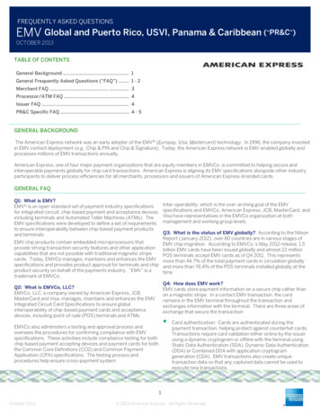
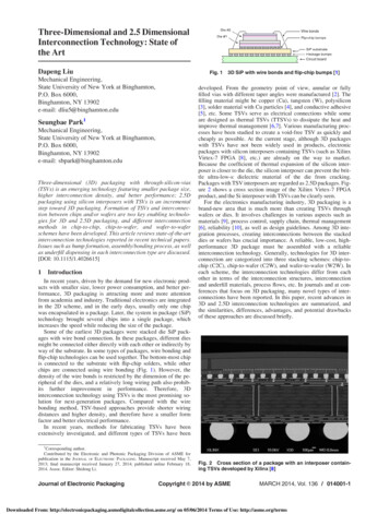
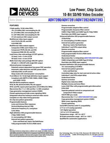
ADV7390/ADV7391/ADV7392/ADV7393Data SheetFUNCTIONAL BLOCK DIAGRAMSVBI DATA SERVICEINSERTIONALSBADV7390/ADV7391MPU PORTSUBCARRIER FREQUENCYLOCK (SFL)VDD IO8-BIT SDOR8-BIT ED/HDSDR/DDRSD/ED/HD INPUT4:2:2 TO RADDBURSTPROGRAMMABLECHROMINANCEFILTER16 FILTERYCrCbTORGB16 FILTERSIN/COS rTORGB MATRIXPROGRAMMABLEED/HD FILTERSHDTVTESTPATTERNGENERATORHSYNCCLKINDAC 111-BITDAC 2DAC 211-BITDAC 3DAC 3REFERENCEAND CABLEDETECT16 /4 OVERSAMPLING PLLVSYNC11-BITDAC 14 FILTERSHARPNESS ANDADAPTIVE FILTERCONTROLVIDEO TIMING GENERATORRESETVAAAGNDSFLPGND EXT LFPVDDRSET06234-001GND IOSDASCLMULTIPLEXERVDD (2)DGND (2)COMPFigure 1. ADV7390/ADV7391 (32-Lead LFCSP)SCLVBI DATA SERVICEINSERTIONSDAALSBADV7390BCBZMPU PORTSUBCARRIER FREQUENCYLOCK (SFL)VDD IO8-BIT SDSDR/DDRSD INPUT4:2:2 TO ROMINANCEFILTER16 FILTER16 FILTERSIN/COS DDSBLOCKVIDEO TIMING GENERATORHSYNCVAAAGNDSFLCLKINPVDDDAC 1REFERENCEAND CABLEDETECT16 OVERSAMPLING PLLVSYNC11-BITDAC 1PGND EXT LFRSET06234-146GND IOVDD (2)MULTIPLEXERDGND (2)COMPFigure 2. ADV7390BCBZ-A (30-Ball WLCSP)SCLSDAALSBSDR/DDRSD/ED/HD INPUT4:2:2 TO 4:4:4DEINTERLEAVEAGNDMPU PORTRGBTOYCrCbMATRIXSUBCARRIER FREQUENCYLOCK DDBURSTPROGRAMMABLECHROMINANCEFILTERSIN/COS DDSBLOCK16 FILTER16 RMANAGEMENTCONTROLRESETPROGRAMMABLEED/HD FILTERSYCbCrTORGB MATRIXVIDEO TIMING GENERATORHSYNCVSYNC16x/4x OVERSAMPLING PLLCLKINRev. J Page 6 of 10712-BITDAC 1DAC 112-BITDAC 2DAC 212-BITDAC 3DAC 34 FILTERSHARPNESS ANDADAPTIVE FILTERCONTROLPVDDFigure 3. ADV7392/ADV7393 (40-Lead LFCSP)Downloaded from Arrow.com.VAAADV7392/ADV7393VBI DATA SERVICEINSERTIONVDD IO8-/10-/16-BIT SDOR8-/10-/16-BIT ED/HDSFLPGND EXT LFREFERENCEAND CABLEDETECTCOMPRSET06234-145GND IOVDD (2)MULTIPLEXERDGND (2)
Data POWER SUPPLY SPECIFICATIONSAll specifications TMIN to TMAX ( 40 C to 85 C), unless otherwise noted.Table 3.ParameterSUPPLY VOLTAGESVDDVDD IOPVDDVAAPOWER SUPPLY REJECTION 1.893.631.893.465VVVV%/%INPUT CLOCK SPECIFICATIONSVDD 1.71 V to 1.89 V, PVDD 1.71 V to 1.89 V, VAA 2.6 V to 3.465 V, VDD IO 1.71 V to 3.63 V. All specifications TMIN to TMAX ( 40 Cto 85 C), unless otherwise noted.Table 4.ParameterfCLKINConditions 1SD/EDED (at 54 MHz)HDMinCLKIN High Time, t9CLKIN Low Time, t10CLKIN Peak-to-Peak Jitter Tolerance1Typ275474.25Max40402UnitMHzMHzMHz% of one clock cycle% of one clock cycle nsSD standard definition, ED enhanced definition (525p/625p), HD high definition.ANALOG OUTPUT SPECIFICATIONSVDD 1.71 V to 1.89 V, PVDD 1.71 V to 1.89 V, VAA 2.6 V to 3.465 V, VDD IO 1.71 V to 3.63 V. All specifications TMIN to TMAX ( 40 Cto 85 C), unless otherwise noted.Table 5.ParameterFull-Drive Output CurrentLow-Drive Output CurrentDAC-to-DAC MatchingOutput Compliance, VOCOutput Capacitance, COUTAnalog Output Delay 2DAC Analog Output Skew12ConditionsRSET 510 Ω, RL 37.5 ΩAll DACs enabledRSET 510 Ω, RL 37.5 ΩDAC 1 enabled only 1RSET 4.12 kΩ, RL 300 ΩDAC 1, DAC 2, DAC 3Min33Typ34.6Max37UnitmA31.533.537mA4.32.00DAC 1, DAC 2, DAC 31.41061The recommended method of bringing this value back to the ideal value is by adjusting Register 0x0B to the recommended value of 0x12.Output delay measured from the 50% point of the rising edge of the input clock to the 50% point of the DAC output full-scale transition.Rev. J Page 7 of 107Downloaded from Arrow.com.mA%VpFnsns
ADV7390/ADV7391/ADV7392/ADV7393Data SheetDIGITAL INPUT/OUTPUT SPECIFICATIONS—3.3 VVDD 1.71 V to 1.89 V, PVDD 1.71 V to 1.89 V, VAA 2.6 V to 3.465 V, VDD IO 2.97 V to 3.63 V. All specifications TMIN to TMAX ( 40 Cto 85 C), unless otherwise noted.Table 6.ParameterInput High Voltage, VIHInput Low Voltage, VILInput Leakage Current, IINInput Capacitance, CINOutput High Voltage, VOHOutput Low Voltage, VOLThree-State Leakage CurrentThree-State Output CapacitanceCondition
Lead frame chip scale package (LFCSP) op tions . 32- lead, 5 mm 5 mm LFCSP . 40- lead, 6 mm 6 mm LFCSP . Wafer level chip scale package (WLCSP) option . 30- ball, 5 6 WLCSP with single DAC output . Advanced power management . Patented content -dependent low power DAC operation . Automatic cable detection and DAC power -down