Transcription
UNCLASSIFIEDNETWORK MANAGEMENTSECURITY GUIDANCE AT-A-GLANCEVersion 9, Release 124 August 2017Developed by DISA for the DoDUNCLASSIFIED
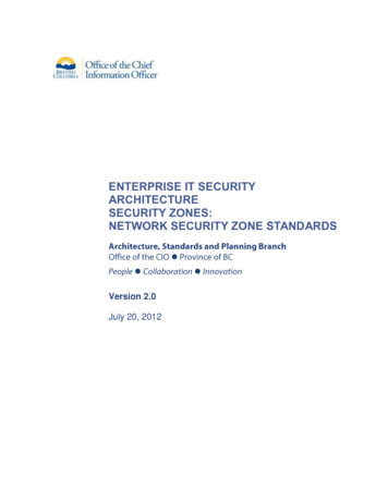
UNCLASSIFIEDNetwork Management Security Guidance At-a-Glance, V9R124 August 2017DISADeveloped by DISA for the DoDTABLE OF CONTENTSPage1. INTRODUCTION . 12. MANAGEMENT NETWORK . 22.1 Network Element Access for OAM&P . 22.2 Out-of-Band Management Network . 32.2.1 Dedicated OOBM Infrastructure. 32.2.2 Virtual OOBM Backbone . 42.2.3 Non-Dedicated OOBM Gateway Routers – Dedicated OOBM Backbone . 42.2.4 Non-Dedicated OOBM Gateway Routers – Virtual OOBM Backbone . 52.2.5 Non-Dedicated OOBM LAN Infrastructure . 62.2.6 OOBM Interface . 72.3 In-Band Management Network . 72.3.1 Physical Management LAN . 82.3.2 Management VLAN. 92.3.3 NOC Connectivity . 92.3.4 Management Traffic Quality of Service . 102.4 SNMP . 103. NETWORK MANAGEMENT AUXILIARY COMPONENTS . 123.13.23.33.4Syslog Server . 12Communications Servers . 13AAA Server . 13NTP Client and Server . 144. LOGISTICS: IMAGE AND CONFIGURATION STORAGE . 16iiUNCLASSIFIED
UNCLASSIFIEDNetwork Management Security Guidance At-a-Glance, V9R124 August 2017DISADeveloped by DISA for the DoDLIST OF TABLESPageTable 1: Icons Used In This Document . 1Table 2: Log Severity Levels . 12iiiUNCLASSIFIED
UNCLASSIFIEDNetwork Management Security Guidance At-a-Glance, V9R124 August 2017DISADeveloped by DISA for the DoDLIST OF FIGURESPageFigure 1: OOBM Access to the Managed Network . 3Figure 2: Remote Site OOBM Connectivity via GRE/IPsec . 4Figure 3: Non-Dedicated OOBM Gateway with Dedicated OOB Backbone. 5Figure 4: Non-Dedicated OOBM Gateway – Connectivity via GRE over IPsec . 6Figure 5: Non-Dedicated OOBM LAN Infrastructure. 7Figure 6: Physical Management LAN . 8Figure 7: Management VLAN Separation . 9Figure 8: In-Band Management Traffic Separation . 10ivUNCLASSIFIED
UNCLASSIFIEDNetwork Management Security Guidance At-a-Glance, V9R124 August 2017DISADeveloped by DISA for the DoD1. INTRODUCTIONNetwork management is the process of monitoring network elements, configuring networkelements to turn up and disable network services, and the collection of state information andother relevant data about each element to ensure availability and that services are being deliveredto meet or exceed service level agreements. Network management processes can be performedon-site by the local network administrators and engineers or remotely at a Network OperationsCenter (NOC).Whether a production network is being managed locally or from a NOC, achieving networkmanagement objectives depends on comprehensive and reliable network management solutions.These solutions provide monitoring of network behavior, performance thresholds, and networkelement configuration. Equally important is the ability to quickly detect and troubleshootnetwork events such as a service outage, link down, node down, and high utilization of bothnetwork elements and bandwidth.The intent of this document is to discuss the best network management practices that should beimplemented and to provide easy-to-follow guidance to securely manage networks. A largeportion of the guidance found in Section 2, Management Network, will be dependent on both thephysical and logical network topology, as well as the specific network management deploymentbased on various out-of-band (OOB) and in-band management paradigms.Table 1: Icons Used In This DocumentRouterAccess SwitchMulti-Layer SwitchIDS/IPSFirewallNetworkGRE/IPsec Tunnel802.1Q Trunk LinkDesktopTerminal ServerSecured ModemServer1UNCLASSIFIED
UNCLASSIFIEDNetwork Management Security Guidance At-a-Glance, V9R124 August 2017DISADeveloped by DISA for the DoD2. MANAGEMENT NETWORKManagement systems provide the network operator the facility to manage the network and all ofits components. They are both the platforms and the applications that interact with the managednetwork elements to provide the NOC with a framework to facilitate operation, administration,maintenance, and provisioning (OAM&P) tasks. OAM&P is a group of management functionsthat enables system or network fault indication, diagnostics, performance monitoring, securitymanagement, configuration management, and service provisioning. Management systems andmanaged network elements need to be interconnected. The facility that provides this connectionis referred to as the “management network”.To be managed, a network element provides a management interface through which amanagement system can communicate. Hence, the management system is the reason for themanagement network to exist. The management network is composed of network managementworkstations, authentication servers, syslog servers, time servers, communications servers,NetFlow collector, an Operations Support System (OSS), and a network for transportingmanagement traffic. While the Network Infrastructure STIGs and SRGs provide guidance forsecuring a network and the network elements, this document will discuss the managementconnectivity models used to access the network being managed, as well as all of the managementnetwork components, the vulnerabilities they introduce, and the security measurements that mustbe taken to mitigate these risks.2.1Network Element Access for OAM&PSecuring the network infrastructure is critical to overall network security. A key element is thesecurity of management access to the network elements. If device access is compromised, thesecurity end of the entire network cam be compromised. To provide management access,network elements support direct serial connections, out-of-band connections, and in-bandconnections. The direct serial interface is typically referred to as the craft port or console port.There may also be an auxiliary port. This interface is intended to be an access port through whichlocal operation control and configuration management can take place.In-band or out-of-band connections can be used to transport network management messagesbetween the managed network elements and the management systems used for providingOAM&P functions. In either case, the same access services, such as Secure Shell (SSH),Transport Layer Security (TLS), Secure Sockets Layer (SSL), HyperText Transfer Protocol overTLS or SSL (HTTPS), and Simple Network Management Protocol (SNMP), are used to access amanaged network element. Out-of-band and in-band management implementations will bediscussed in Sections 2.2 and 2.3 respectively.The auxiliary port, console port, and any slow-speed async serial port with an analog modemconnected to it provides the capability for direct dial-up administrative access. If dial-upcapability is provided, a secured modem and connection must be used as specified in Section 3.2.2UNCLASSIFIED
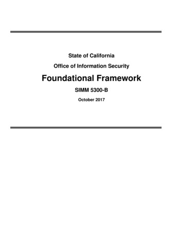
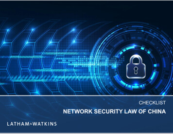
UNCLASSIFIEDNetwork Management Security Guidance At-a-Glance, V9R124 August 20172.2DISADeveloped by DISA for the DoDOut-of-Band Management NetworkThe Out-of-Band Management (OOBM) network is an IP network used exclusively for thetransport of OAM&P data from the network being managed to the OSS components located atthe NOC. Its design provides connectivity to each managed network element, enabling networkmanagement traffic to flow between the managed network elements and the NOC. This allowsthe use of paths separate from those used by the network being managed. The NOC could belocated locally or remotely at a single or multiple sites, all connecting to the OOBM network.OOBM networks isolate network users from communication channels that are dedicated tonetwork management.2.2.1Dedicated OOBM InfrastructureAll managed devices are connected to the OOBM access switch via the managed elements’OOBM interface. The OOBM switch provides connectivity between the OOBM router and themanaged network elements. As depicted in Figure 1, the OOBM access switch, the OOBMgateway router, and all of the managed network elements’ OOBM interfaces are essentially theOOBM remote site LAN.Figure 1: OOBM Access to the Managed NetworkThe OOBM router is the gateway between the network elements being managed and the OOBMbackbone. Using dedicated paths, the OOBM backbone connects the OOBM gateway routerslocated at the premise of the managed networks and at the NOC. Dedicated links can bedeployed using provisioned circuits or Multiprotocol Label Switching (MPLS) L2VPN/L3VPN3UNCLASSIFIED
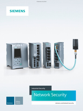
UNCLASSIFIEDNetwork Management Security Guidance At-a-Glance, V9R124 August 2017DISADeveloped by DISA for the DoDservices. An alternative is implementing a secured path via IPsec tunnels connecting the OOBMgateway routers.2.2.2Virtual OOBM BackboneIn deployments lacking dedicated OOBM links, the NOC must connect to the OOBM remote siteLAN via shared network infrastructure such as the NIPRNet. Figure 2 illustrates a topology withthe NOC and the OOBM remote site LAN securely connected via GRE over IPsec tunnelsbetween the OOBM gateway routers. The GRE tunnel ensures that both the management andcontrol plane traffic will be logically separated from any other traffic traversing the samephysical path. This deployment is implemented by establishing a GRE tunnel between the twogateways. Interior gateway protocol (IGP) routing protocol adjacencies will form over the GREtunnel end points. The GRE tunnel should be encrypted by IPsec to provide privacy for both themanagement and control plane traffic.Figure 2: Remote Site OOBM Connectivity via GRE/IPsec2.2.3Non-Dedicated OOBM Gateway Routers – Dedicated OOBM BackboneIf the gateway router is not a device dedicated for the OOBM network (i.e., may be the managednetwork’s premise router), several safeguards must be implemented for traffic containment andseparation. Management traffic must not leak into the managed network, and traffic from themanaged network must not leak into the management network.4UNCLASSIFIED
UNCLASSIFIEDNetwork Management Security Guidance At-a-Glance, V9R124 August 2017DISADeveloped by DISA for the DoDSince the managed network and the management network are separate routing domains as shownin Figure 3, separate IGP routing instances must be configured on the router—that is, one for themanaged network and one for the OOBM network. In addition, this shared router must beconfigured to ensure that control plane traffic is not redistributed between the two routingdomains. Implementing Virtual Routing and Forward (VRF) on the interfaces connecting theOOBM backbone and the OOBM remote site LAN can provide additional segregation bycreating a separate OOBM routing table. This implementation does not require MultiprotocolLabel Switching (MPLS); hence, it is commonly referred to as VRF-lite. A VRF instance couldalso be created for the managed network, or simply allow it to use the global route table.Figure 3: Non-Dedicated OOBM Gateway with Dedicated OOB Backbone2.2.4Non-Dedicated OOBM Gateway Routers – Virtual OOBM BackboneAs previously discussed, for OOBM deployments lacking dedicated OOB links, secured pathscan be deployed using IPsec tunnels between the gateways. If static routing is used,implementing IPsec tunnel between the non-dedicated OOBM gateway and the OOBM gatewayat the NOC to transport management traffic is a simple and secured deployment. However, sincestatic routes do not scale well, dynamic routing may be required. Hence, control plane trafficmust be able to traverse the same secured path as the management traffic. This deployment isimplemented by establishing a GRE tunnel between the two gateways. IGP routing protocoladjacencies will form over the GRE tunnel end points. The GRE tunnel will be encrypted byIPsec to provide privacy for the control plane payload as illustrated in Figure 4.5UNCLASSIFIED
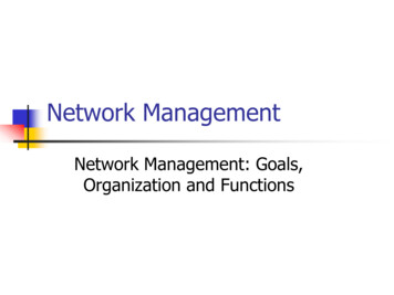
UNCLASSIFIEDNetwork Management Security Guidance At-a-Glance, V9R124 August 2017DISADeveloped by DISA for the DoDFigure 4: Non-Dedicated OOBM Gateway – Connectivity via GRE over IPsec2.2.5Non-Dedicated OOBM LAN InfrastructureFor OOBM deployments lacking dedicated Layer 2 and Layer 3 infrastructure, both VRF-liteand 802.1q technologies can be used to provide the separation of management and productiontraffic. As depicted in Figure 5, VRF OOBM and VRF PROD is used to create separate routingtables for the OOBM network and the managed network respectively. Where Ethernet Layer 3interfaces must be shared, 802.1q tagging can be deployed to provide the separation, therebycreating logical or sub interfaces. The VRFs would be configured and bound to the appropriatephysical or logical Layer 3 interfaces. For simplicity, the VRFs are only called out on R1’slogical interfaces (802.1q) in Figure 5 but would exist on the two physical interfaces between thePremise Router and R1, the Premise Router and R2, and the two logical interfaces between R1and R2.When access switches must be shared between domains, 802.1q tagging can be used to createVLANs for management as well as production domains. As shown in Figure 5, VLAN 10 andVLAN 20 have been deployed to provide separate Layer 2 domains for the OOBM network andthe managed network respectively. In this illustration, the VLAN numbers are only significantwithin each Layer 2 domain. Using the same VLAN numbers also makes it easier to identify theownership of the sub-interfaces on the routers.6UNCLASSIFIED
UNCLASSIFIEDNetwork Management Security Guidance At-a-Glance, V9R124 August 2017DISADeveloped by DISA for the DoDFigure 5: Non-Dedicated OOBM LAN Infrastructure2.2.6OOBM InterfaceThe OOBM access switch will connect to the management interface of the managed networkelements. The management interface can be a true OOBM interface or a standard interfacefunctioning as the management interface. In either case, the management interface of themanaged network element will be directly connected to the OOBM access switch.An OOBM interface does not forward transit traffic, thereby providing complete separation ofproduction and management traffic. Since all management traffic is immediately forwarded intothe management network, it is not exposed to possible tampering. The separation also ensuresthat congestion or failures in the managed network do not affect the management of the device.If the managed network element does not have an OOBM interface, the interface functioning asthe management interface must be configured so that management traffic and production trafficdo not leak into the management network.2.3In-Band Management NetworkThe in-band management paradigm exists when the management traffic takes the same path asoperational or production traffic, thereby using the same Layer 3 interface of the managednetwork element. Management plane traffic shares the same path as the control plane andforwarding plane. Henceforth, network management traffic is intermixed with user traffic usingthe same physical or logical interfaces of the network elements being managed.7UNCLASSIFIED
UNCLASSIFIEDNetwork Management Security Guidance At-a-Glance, V9R124 August 2017DISADeveloped by DISA for the DoDA dedicated in-band management network enables the enclave or enterprise to control, monitor,and restrict management plane traffic. Since all management services must be deployed withinthe management network, all managed devices can be configured to only permit managementplane traffic from the management network IP address space. It is also easier to constructappropriate filters since management plane traffic sourced from the managed devices must bedestined to the management network IP address space.Unlike out-of-band implementation, the configured IP address of the interfaces used to access themanaged elements belong to address space of the managed network. Using a loopback address asthe source address provides security, scalability, and manageability of all routers and switches. Itis easier to construct appropriate ingress filters for management plane traffic destined to thenetwork management subnet since the source addresses will be from the range used for loopbackinterfaces to the larger range used for physical interfaces. Log information recorded byauthentication and syslog servers will record the router’s loopback address instead of thenumerous physical interface addresses. Messages sent to the following servers should also usethe loopback address as the source address: Syslog, TACACS , RADIUS, NTP, SNMP,NetFlow Collector, TFTP, and FTP.2.3.1Physical Management LANAs illustrated in Figure 6, the management network must still have its own subnet in order toenforce control and access boundaries provided by Layer 3 network nodes such as routers andfirewalls. Management traffic between the managed network elements and the managementnetwork is routed via the same links and nodes as that used for production or operational traffic.Safeguards must be implemented to ensure the management traffic does not leak past themanaged network’s premise equipment.Figure 6: Physical Management LAN8UNCLASSIFIED
UNCLASSIFIEDNetwork Management Security Guidance At-a-Glance, V9R124 August 20172.3.2DISADeveloped by DISA for the DoDManagement VLANIf the management systems reside within the same Layer 2 domain as the managed networkelements, separate VLANs will be deployed to provide separation at that level. In this case, themanagement network will have its own subnet and be provisioned with a unique VLAN. Asillustrated in Figure 7, inter-VLAN routing or the routing of traffic between nodes residing indifferent subnets requires a router or multi-layer switch (MLS). Access control lists must be usedto enforce the boundaries between the management network and the network being managed. Allphysical, logical, and virtual (i.e., switch virtual interface) Layer 3 interfaces must be configuredwith ACLs to prevent the leaking of unauthorized traffic from one network to the other.Figure 7: Management VLAN Separation2.3.3NOC ConnectivitySimilar to the OOBM model, when the production network is managed in-band, the managementnetwork could also be housed at a NOC that is located locally or remotely at a single or multipleinterconnected sites. NOC interconnectivity, as well as connectivity between the NOC and themanaged networks’ premise routers, would be enabled using either provisioned circuits or VPNtechnologies such as IPsec tunnels or MPLS L2VPN/L3VPN services. The topology shown inFigure 8 depicts all management traffic between the NOC sites and the managed networkencapsulated within IPsec tunnels traversing the NIPRNet.9UNCLASSIFIED
UNCLASSIFIEDNetwork Management Security Guidance At-a-Glance, V9R124 August 2017DISADeveloped by DISA for the DoDFigure 8: In-Band Management Traffic Separation2.3.4Management Traffic Quality of ServiceQuality of Service (QoS) implementation categorizes network traffic, prioritizes it according toits relative importance, and ensures bandwidth is reserved for important traffic when there iscongestion. Implementing QoS within the network makes network performance more predictableand bandwidth utilization more effective. Most important, since the same bandwidth is beingused to manage the network, it provides some assurance that there will be bandwidth available totroubleshoot outages and restore availability when needed.When management traffic must traverse several nodes to reach the management network,management traffic should be classified and marked at the nearest upstream multi-layer switch orrouter. In addition, all core routers within the managed network must be configured to providepreferred treatment based on the QoS markings. This will ensure that management trafficreceives preferred treatment (per-hop behavior) at each forwarding device along the path to themanagement network.2.4SNMPSNMP enables network administrators to manage network performance, troubleshoot networkproblems, and plan for network growth. An SNMP-managed network consists of three keycomponents: managed devices, agents, and managers, which are commonly referred to as10UNCLASSIFIED
UNCLASSIFIEDNetwork Management Security Guidance At-a-Glance, V9R124 August 2017DISADeveloped by DISA for the DoDnetwork-management systems (NMSs). A managed device is a network node that resides on amanaged network. An SNMP agent is a software module that resides in a managed device.SNMP agents collect and store management information and make this information available tothe NMS.The SNMP manager provides the interface between the network management personnel and themanaged network. The SNMP agent provides the interface between the SNMP manager and thedevice being managed. The manager is the collector of alarm information via SNMPnotifications (i.e., traps and informs) as well as statistical and historical management informationretrieved by polling the agents within the managed network. This information is vital for realtime monitoring and alarm management as well as for strategic planning and performancemanagement. IA measures must be implemented to mitigate the risk of the SNMP manager beingcompromised. To provide security through separation and isolation, the SNMP manager mustreside within the management network. This enables the SNMP manager to provide managementservices to the managed devices using a secured as well as a preferred path.SNMP version 3 provides secure exchanges of management data between network devices andnetwork management systems. The encryption and authentication features in SNMPv3 ensurehigh security in transporting packets to a network management station. SNMPv3 employs theUser-Based Security Model (USM) to provide cryptographic services. The USM uses eitherHMAC-MD5 or HMAC-SHA message digests to ensure message authenticity and integrity andDES-CBC, 3DES, or AES encryption to ensure message privacy. These features are used toprovide three distinct levels of security:1. No authentication with no privacy2. Authentication with no privacy3. Authentication with privacyTo reduce the risk of a managed network element being breached via rogue SNMP manager, bestpractice is to authenticate all SNMP messages using HMAC-SHA and encrypt the payload usingAES cryptographic algorithm using the largest key size supported.11UNCLASSIFIED
UNCLASSIFIEDNetwork Management Security Guidance At-a-Glance, V9R124 August 2017DISADeveloped by DISA for the DoD3. NETWORK MANAGEMENT AUXILIARY COMPONENTSThe network management auxiliary components are used to provide capabilities to enable bothmanagement and security functionality for the managed network. These components are beingsecured as a result of the IA requirements that have been defined based on the topology—that is,whether they are residing within a dedicated OOB network infrastructure or connected to an inband network. Nevertheless, since they do have sessions with elements in the managed networkthat could be compromised, additional IA measures must be followed to reduce the risk of thesecomponents also being compromised.3.1Syslog ServerLogging is a key component of any security architecture and is a critical part of network elementsecurity. It is essential that security personnel know what is being done, what was attempted, andby whom to compile an accurate risk assessment. It is also imperative that all configurationchanges to network elements are logged on a per-session and per-user basis. Maintaining anaudit trail of system activity logs can help identify configuration errors, understand pastintrusions, troubleshoot service disruptions, and react to probes and scans of the network.Log severity levels 0–6 are the levels required to collect the necessary information to help in therecovery process.Table 2: Log Severity LevelsLevel01234567Level ationsDescriptionRouter becoming unusableImmediate action neededCritical conditionError conditionWarning conditionNormal but importanteventInformational Information messageDebuggingDebug messageExampleIOS could not loadTemperature too highUnable to allocate memoryInvalid memory sizeCrypto operation failedInterface changed state, up or downPacket denied by access listAppears only when debugging is enabledA syslog server provides the network administrator with the ability to configure all of thecommunication devices on a network to send log messages to a centralized host for review,correlation, reporting, and storage. This implementation provides for easier management ofnetwork events and is an effective facility for monitoring and the automatic generation of alertnotification. The repository of messages facilitates troubleshooting when problems areencountered and can assist in performing root cause analysis. Syslog files can also be parsed inreal time to identify suspicious behavior or be archived for review at a later time for research andanalysis.12UNCLASSIFIED
UNCLASSIFIEDNetwork Management Security Guidance At-a-Glance, V9R124 August 20173.2DISADeveloped by DISA for the DoDCommunications ServersA communications server, also known as a terminal server, can be used to provide connectivityamong all managed network elements and the OOBM gateway router for administrative accessto the device’s console port. In the event the OOBM network is not able to provide connectivitydue to an outage, the communications server can provide a dial-up Point-to-Point Protocol (PPP)connection to access a network element. PPP provides two options that must be used to helpsecure the connection at the link layer: authentication and callback. The communication serverand remote client negotiate these options during connection establishment by the Link ControlProtocol (LCP)—a PPP sub-layer.PPP enables authentication between remote clients and access servers using either PasswordAuthentication Protocol (PAP) or Challenge Handshake Authentication Protocol (CHAP). PAPprovides a simple way for the remote client to establish its identity with an authenticator: a twoway handshake after the initial PPP link establishment. A username/password pair is sent by theremote client to the access server until authentication is acknowledged or the connection isterminated.CHAP is a stronger authentication method than PAP and therefore is the preferredimplementation. CHAP creates a unique challenge phrase (a randomly generated string) for eachauthentication. The challenge phrase is combined with device host names using one-way hashingfunctions to authenticate. Hence, no static secret information is ever transmitted. CHAP can alsobe set up to do repeated mid-session authentications. This is useful for dial-up PPP sessionswhere a port may be left open even though the remote device has disconnected. In this case, it ispossible for someone else to pick up the connection mid-session simply by establishingconnectivity.Callback increases the level of security by allowing connection only to authorized telephonenumbers. When callback is enabled, a user calls the access server. After successfullyauthenticating the call, the access server notifies the user that the user will be called back. Theserver hangs up immediately and calls back using a preconfigured number. Modems can alsoprovide the call-back capability.The auxiliary port, console port, and any slow-speed async serial port with an analog modemconnected to the managed device also provides the capability for direct dial-up administrativeaccess for infrastructures that do not have a communications server for management access.The modems providing the end-to-end connection between the network administrator and thecommunication server or the managed device must establish a secured link using a FIPS 140-2encrypt
Network Management Security Guidance At-a-Glance, V9R1 DISA 24 August 2017 Developed by DISA for the DoD 3 UNCLASSIFIED 2.2 Out-of-Band Management Network The Out-of-Band Management (OOBM) network is an IP network used exclusively for the transport of OAM&P data from the network being managed to the OSS components located at the NOC.