Transcription
PERSIST-Pressure EqualizedRain Screen Insulated StructureTechnique-Design ApproachChris B. MakepeaceBarrie T. DennisABSTRACTMany buildings have problems with the pel/orm(lnce and durability a/their ellvelopes largely related 10 inadequate control ofair leakage. The discovery a/the shor/comings in achieving the e.\pected pelionnance is offen only realized when the buildillgis;1I operatioll, even/hough mall)' problems call oftell be predicted simply by review of the constructioll docliments. Buildingswith envelope problems are rarelY;1l imminent danger ofcollapse, but by llofjuljillillg their intended purpose and increased oper ating Gild repair costs, tlley can become a liability. Buildblg owners alld operators are further affected by litiga,;oll over comfort,health, alld safety issues.111e Pressure Equalized Rain Screelllnsulated Structure Technique, PERSIST, is recommended by Alberta Public Works in thedesign o/new buildings. This approach is also recommended/or the retrofit 0/existing bllildings with seriolls envelope problems.This paper discusses the PERSIST design concept and some a/the construction details and method. . that enhance its application.INTRODUCTIONIn cold climates many buildings have problems with theperformance and durability of their wal1s, windows, and roofsbecause of inadequate control of air and water movement(Hutcheon and Handegord 1983). In large part, these problemsarise because there are unintentional, often hidden, openingsin the building envelope. These openings are present eitherbecause the construction was discontinuous to start with or theelements intended to stop the movement of air and waterfailed.Investigations of many buildings in Alberta with air leakage problems have revealed striking similarity in the sourcesof these problems:Inadequate details for penetrations through and connections with walls and roofs.Designs that ignored constmctability of the air barriersystem.Constructions that did not allow drainage or drying.Use of materials that did not withstand the loadsimposed.Alberta Public Works (Supply and Services, TechnicalResources and Standards Division) has for Illany yearsencouraged a fail-safe design approach to avoid these problems. This approach has long been known and advocated bynumerous building science researchers, investigators of build ing envelope problems, and some designers and buildingmaterial suppHers. Review of construction using this technique has shown it to be quite forgiving to the imperfectionsand surprises normally found in most construction projects.This is the same approach that has been articulated in ntlluerous Canadian Blliiding Digests from the National ResearchCouncil Canada and also in Brand and Van Norstrand (1990).However, as far as the authors can determine, the approachdescribed below has remained unnamed, unlike otherapproaches sllch as the airtight drywall and face seal approach.With the Latin saying, "Nomen est numen (To name is toknow)" in mind, we have coined the term PERSIST (PressureEqualized Rain Screen Insulated Stmcture Technique) to aidin understanding. This approach to the arrangement of themain functional components of walls has been described asfollows:"The advantages inherent in designs based on the openrain screen principle go far beyond those associated withrain penetration control. .Movements and minor imperfections in the joint seal between prefabricated componentsbecome less critical, and the life of sealants is extended byChris B. Makepeace is manager of the \Valls ,md Windows Section and Barrie T. Dennis is manager of the Roofing Section in the BuildingSciences Branch, Alberta Govemment Public \Vorks, Edmonton, Alberta, Canada.Thermal Envelopes VIIIPelformance 0/ Air Barrier Systel11s-Practices767
shading from solar radiation. Although there may be problems regarding adequate ties and support of the rain screenwhen this principle is applied to the total wall covering, itshould be noted that the exterior cladding is relieved ofmuch of the normal wind load. It must be resisted by theremainder of the wall. A complete rain screen approach canresult in easy handling of cladding movements and cracksafter constmction, and in reducing air conditioning loads,and permits rapid drying of cladding materials. It alsopermits the better positioning of insulation and minimizesthe risk of condensation within the wall. With the manyadvantages of the open rain screen, its full developmentshould be pursued by all building designers" (Kerby 1963)."Application of insulation over the entire exterior of awaH provides an ideal solution of the problems by thermalbridges. Although a light cladding is required to protect thewall, the number and size of the supporting ties that passthrough the insulation are small" (Brown and Wilson1963).Hutcheon (1964), by applying the PERSIST principles toa masonry wall, demonstrated the many advantages of thatconfiguration. These included reduced thermal effects on thestructure, inner wythe, and windows, reduced rain penetration and reduced wind loads on the cladding, reduced problem of thermal bridges, reduced possibility of degradation bywetting and wet freezing, and greater tolerance for movements in the cladding.Garden (l965a, 1965b) illustrates some of the differences between wall and roof design and some of the necessary compromises but importantly advises,"Ease the dutiesimposed on each material by judicious selection and positioning in the assembly."Latta uses precast concrete construction as an example ofthe application and advantages of PERSIST. Others, such asBrand and Van Norstrand (1990), reiterate the PERSIST principles with the following:The Rules1."Enclose the building in a continuous air barrier.2.Provide continuous supp011 for the air (seal) banieragainst wind loads.3.Ensure that the air (seal) balTier is flexible at joints wheremovement may occur.4.Provide continuous insulation to keep the air bmTierwarm and to conserve energy in the building.S.Keep the insulation tight to the air balTier.6.Protect the insulation with a rain screen/sun screensllpp0l1ed out from the stmcture in a way that does notpenetrate the insulation with excessive heat bridges.7.Provide enough open space for drainage and constmctionclearances between the rain screen and the insulation.8.Drain the wall cavity to the outside."768PRESSURE EQUALIZED RAIN SCREENINSULATED STRUCTURE TECHNIQUEThe term pressure equalized is intended to apply not onlyto the concept of pressure equalization of cladding and joints,as described in Kerby (1963), but to whole building pressureequalization. Overpressurization of building interiors shouldbe avoided. The term insulated structure refers to the practiceof placing the insulation to the outside of the stmctural frameas opposed to insulating inside or between the structural frame(Figures 2 and 3). When the insulation is situated outside thestmctural frame, installation of the air sealing elementbecomes much easier and its performance greatly improved.Increased airtightness of the building envelope ironicallycreates a need for mechanical system designers to adjust theirbuilding leakage estimates so that overpressurization does notoccur. The conventional compact roof design, while general1ynot pressure equalized, although it can be, exemplifies theinsulated structure concept in that the position above the structure makes the process of obtaining continuity simple. Wheresuch roofs join walls or parapets, obtaining continuity isgreatly eased when a protected membrane detail is used(Figure 4).PERSIST can accommodate more stringent interior environments, while at the same time allowing the flexibilitynecessaty for a variety of aesthetic design approaches. Thistechnique is based on a sequence of steps in the constructionof the building envelope, which differs only slightly fromnormal practices. It is helpful to consider the envelope as aseries of planes.The structural framework and infill walls are constructedto maintain, as much as possible, simple planes fromfoundation to wall and from wall to roof. A wide varietyof structural and infill systems can be used but with asfew variations in plane as possible.A bituminous membrane (air sealing element) is fullyadhered to the exterior plane of the structure and infil1wall elements. Penetrations of this plane required to support the exterior cladding(s) are designed to: minimizethermal bridging, endure occasional wetting, allow forconstruction tolerances, and allow the membrane to easily achieve an air seal. Other penetrations for mechanicaland electrical are also specifically designed to be sealedat the membrane plane. The membrane acts to seal thestructure and infill walls to fulfill the air barrier functionof the building envelope. Note that this system must bedesigned to withstand the imposed loads of stack effect,mechanical pressurization, and wind pressures.Insulation is mechanically fastened tight to the air batTiersystem. This prevents air from circulating behind theinsulation and reducing its effectiveness and ensures thatthe membrane is kept warm at or near the interior building temperature.The cladding is installed exterior of the insulation, creating an air space that can be pressure equalized throughopenings. The openings at the bottom of the claddingThermal Envelopes VIIIPelformance of Air Barrier Systems-Practices
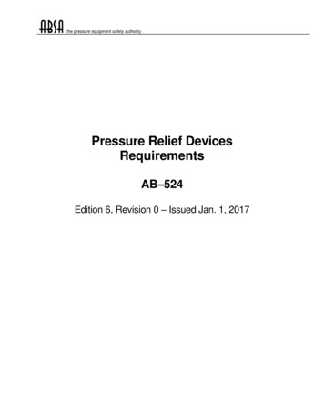
aD ,, , , S 0, , IS -, ", 1:----" I30 0; IPERSISTplusBATTIrq/Iii1 .PERSISTa 10'-- f .: --. S·oIfl II"ADA(SO,!)EDMONTONJAN. 5TH YEARFigure 1WALLTYPESEMPTIED calculated moisture accumulation.should allow water, which may pass through the exteriordadding, to drain. Compartmentalization should beattempted in the design where possible.The glazing system(s) should be selected and positionedfor similar pClformance. The details provided in thispaper show the use of an exterior glazed pressure equalized rain screen window. Continuity of the air seal isachieved by the use of membrane adhered to the membrane of the wall and adhered to the aluminum frame atits plane of air seal. The membrane is additionallymechanically secured to the frame by an anti-rotation channel and screws.Advantages and Benefits of PERSISTElectrical and mechanical services can be nm within theexterior backup wall cavity. Where these services penetrate the plane of air sealing, they can be easily sealedduring construction.Special detailing is not necessary for future interior renovations to ensure airtightness of the drywall.The structure of the building is interior of the plane ofinsulation, thereby minimizing thermal movement.Thermal bridging of the structure is not prevalent.The sequential approach of material installation promotesgood construction detailing, construction, and inspection.If small imperfections do occur within the plane of the airseal, the resulting condensation from exfiHration wouldoccur most likely in the drained cavity between the clad- ding and membrane. Large leakage openings, whichcould allow condensation during conditions of infiltration(windward side), are unlikely to be constructed.Maintenance of exterior caulking, while still importantin minimizing water entry into the wall cavity, is nowmore a visual concern rather than a key to the buildingenvelope providing separation between inside and outside environments as it would be in a face seal design.The air seal is protected from UV degradation and thermal cycling.Additional insulation may, under some conditions, beinstalled interior of the membrane within a stud wallinfill system in buildings with low interior humidity levels. For example (Figure I), when modeled in the computer program EMPTIED using the climatic data forEdmonton over a five-year period (the assemblies ADA[RSI 2.11] and PERSIST with batt [RSI 5.29]), withinsulation interior of the plane of air seal, an accumulation of moisture at high interior humidity levels wasindicated. It should be noted that the calculations did notmodel mechanical pressurization of the buildings. Thisshows the inherent safety of PERSIST (RSI 10).When retrofitting existing buildings with PERSIST, thebuilding can remain occupied as the majority of theimplementation is from the exterior.The design freedom afforded by PERSIST is just beingrecognized. Cladding systems do not have to be restricted tothe immediate location of the structure of the waIL Architectural articulations can be more flexible, as they do not have toThermal Envelopes VIIlPelformallce of Air Barrier Systems-Practices769
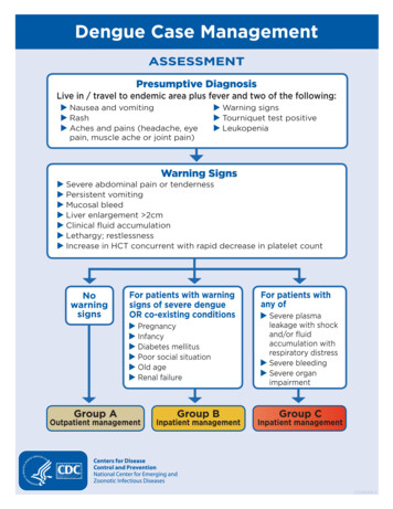
IIJVEMHHGAP [lE: IGNE(i TOACCOIPJOtJATE:u) {:LA8 DEFlEI;TION DUETO LIVE .r,. DEAD LOAOHW,0) CONCRETE f;flEEP AtlD ;HRINKA[jE J r::) EXPAtWION (IF BRII;Kt;UN TRllt:TIO:-JTRAt;K.4Illf-------- VEATlI;AL:.:TRUCTtJRAl ;TEEl[JIlPPtlRT FORPARAPET A NECE GARY. MllfH BEAIR DEALEO AT THEPLANE OFPENETRATION LJFcLAY BRleKf;nRRIJ!;JoN m'J"-fANT----FAGTENERG---------MECHANICALLY FA:;TENEO,AIR SEAL MEIABRANE.TRAN1;}TION AIR ;EAl ME!JBRANE.AlP. f;EALV,EUflRANE/VAf'lllJRBAfiRIER.MO(IIfIEO BITUMENAIR SEAL MEMfiRANE. - R'"I)F DRYWAllTHERMAL BARRIEk.AIR tiPACEPly\\1JfJD TOEXTERIOR tiHEATHIfl(j :UPPoRTMEI1BRANE AIR :;EAl&. EOHATE TO REtiJ!;TWHiD LIIA[I.Roo/parapet detai/.conform to the plane of the air seal. Lightweight c1addingssuch as fabrics can provide the building with a multi-facetedexterior, while the base building is an economical layout.Variations of PERSIST using insulated panels exterior ofthe structure are possible provided that the attachment ofpanels allows access for air sealing at supports and paneljoints.The use of membranes adhered to the backup waH wasintroduced to Alberta in the early 1980s. Since then it hasgained acceptance in other parts of Canada and the northernUnited States. The membrane can be either self-adhered (SA)or thermally fused (TF) to the backup wall.The self-adhering membranes have a release paper on oneside. The most common SA membranes in Alberta lise polyethylene as the carrier and reinforcement for the SBS bitumen,which can vary in thickness but is commonly about 1.2 mmthick. The polyethylene can be subject to damage by subsequent trades so there is sometimes a need for more stringentinspection. Joints of the membrane are lapped in a shinglefashion to allow water to flow over the joint. Some manut lc turers have additional compatible sealants that they recommend for some joint applications. With adhesion only on oneside of the membrane, the need to simplify the planes to whichthe membrane must adhere is beneficial. These membranesare recommended for retrofit projects where the building isoccupied as there is not a potential for fire. Cold temperaturelimitations (-5 C) must be carefully followed in winterconstruction to ensure proper adhesion.770eUILT·UP ROOFING TEEl i:jf(lD WITH. -. TOP & COTTO'"O.C. MAXWUM.Figure 2(iAlltiE.--- PLywl)f)[)TOlERANI;E.VENTt; :jPACEO- - -.HORIZONTALLY AT (;00 [,111RIGJO INSIlLATION JMETAL 4MEMBRANE.DUE TU MUI:.;TIIRE t.THEfl\lAl GHANUE! ,0)PREFlNI :HEOFlMHINJiThermalfllsible membranes have either a glass fiber orpolyester reinforcement with SBS on both surfaces. Variousrelease surfaces are used to keep surfaces of SBS from adhering before installation. Thermalfllsible membranes are appliedby melting off or imbedding the release material in order thatthe SBS can be melted so that it will flow and key into thesmt'ace of the wall. The potential for fire with some substratesmust be carefully reviewed by the designer. A fire watchshould be undertaken after every day's work to minimize therisk. Jointing of the TF membrane is lapped and heated to fusethe SBS of both sheets. A few manufacturers have fonnulatedthe SBS to be installed as a peel and stick and at the same timesome heating can be used without damaging the reinforcing ofthe membrane.The wall structure and backup shown in Figure 2 arecomposed of a steel frame, columns, and beams with metalstud infill and exterior grade gypsum board. This could be avariety of other structural and infi11 systems. The roof isdetailed as open web steel joists, metal deck, and gypsumboard. An SBS membrane fully adhered to the exterior of thegypsum board seals the structure to create the air barriersystem.While the air seal membrane could in theory be installedlip and over the parapet, the detail shown (Figure 2) installs themembrane through the parapet at the plane of air seal of theroof. This prevents moist interior air from entering into theparapet construction and condensing.Thermal Envelopes VIIIPel.fornumce of Air Barrier Systems-Practices
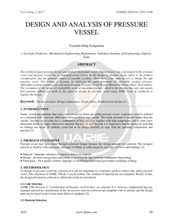
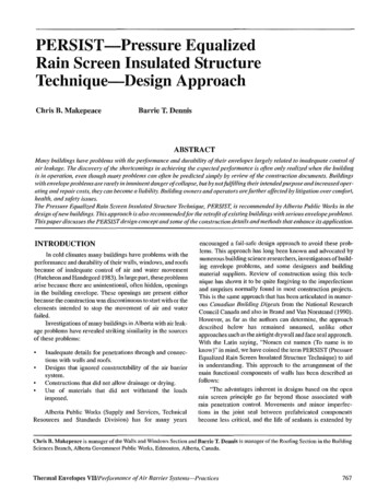
CLAY BRICKVENEERNOTE:METAL PLATE ::HOULD BEKEPT IN LINE WITHFACE OF ORW/ALL: HEATHIN/l.AlLCi.'/ 50mm CLEARANCEIrAROUND ANr:HfJR SUPPORTFOR ATTAcHMENT OF AIR:'EAL MEMBRANE.VENT DRAIIIA!;EPREFINISHEOMETAL FLASHINGSLIP .IOINT ANI;HORINSTALLED IN VERTICALTlIBE ::EGTlON:: f" - 1Iil--(DEFLECTION DESIGII IFNEGE SARY) [IRAINA(iE OFIJlAZINH RABBETL . EXTEP.IIlR GLAZEDPRESSliRE EQUALIZED--- AND DRAINED ANO[IIZE[!ALUMINUM BOX SEf;TIONUo----·--Figure 38EALEO IJNITWindoll' head de/ail (PERSIST).A galvanized sheet metal angle can be introduced toprovide structural support for the membrane at the roof to walltransition to accommodate alternative constructions.Plywood is substituted for the gypsum board at the roofperimeter to avoid construction damage and provide solidbacking for the parapet. A detail to allow penetration of structural steel through the plane of the air seal has been developed.The detail incorporates a steel weld plate at the plane of airseal, which allows a minimum 50 111111 of adhesion surfHce forthe membrane. This weld plate can then have a channel, tube,or gusset welded to it depending on the support needed.The insulation at the roof perimeter is end wrapped as abackup against water ently into the roof insulation. The roofing stripping is carried over the parapet and is protected bymetal flashing.Figure 3 depicts the steel plate at the plane of the air sealas described in Figure 2. In this detail the gussets which arewelded to it to support the exterior masonry are offset to allowfor adequate adhesion of the membrane to the wall stmcturesurrounding the window opening.A pressure-equalized and drained rain screen window isinstalled using anchorage of the main frame, which will allowunintenupted adhesion of the membrane from the surroundingwall to the tube face of the glazing rabbit. Removal of thescrew spline at the mullion junctions is necessary for continuous adhesion of the membrane. An anti-rotation channelmechanically fastens the membrane to the tube face andprovides a surface to mechanically secure metal perimeterflashings. No caulking is necessmy.The window framing system uses dry, keyed-in gasketsboth as the interior air seal and the exterior weather seal foraesthetic and long-term maintenance concerns. The glazingrabbit is drained to the exterior through slots in the pressureplate and in the cover cap.The detail shown in Figure 4 terminates the rain screencladding at a sufficient height above the roof plane to allow themembrane of the roofing to adhere to the membrane of thePERSIST wall. Plywood is installed on the wall stmcture toallow for nailing of roof stripping to the wall. Membranes areshingled to ensure that water cannot enter the roofing system.The roofing insulation is end wrapped.The wall insulation is continued below the cavity and ina protected membrane design, held in pJace by vertical flUTingthat is secured through the insulation and membrane to theplywood. The furring then allows prefinished metal flashingto be mechanically fastened to it to protect the insulation andprovide an aesthetic finish to the transition.CONCLUSIONPERSIST is by no means a panacea to allihe ills of building construction today. The application of PERSIST hasdistinct advantages in terms of design flexibility, constructability, and building performance. This technique allows thevarious components of the building envelope to efficientlyresist the imposed environmental loads, resulting in greaterThermal Envelopes VIliPelformance of Air Barrier Systems-Practices771
MASONRY SliPPORTLINTEL FASTENED TOSTEEL PLATE IN PLANEOF AIR SEAL BYGUSSETS,MASONRY TIElINSULATION CLIPROOF STRIPPING I'IITHGUSSETSTYPE 4 POLYSTYRENE '----,PREFINISHED METAL -,'--,-,-,-"- 'r---FLASHING ONGALVANIZED HATCHANNEL8 FASTENEDBACK TO PLYI'IODD,NO FASTENERS 50 mmABOVE CANT,3/4' PLYWOOD TOSUPPORT ROOFINGTERMINATIONMEMBRANES,ROOFINGEND WRAPROOF VAPOUR BARRIERAIR SEAL MEMBRANEFigure 4 Rooflwall}1l11ctiol1 detail.control of the interior environment. CutTent construction practices are not substantially changed by this technique.Baker, M, 1980, Roo/s, Multi Science Publications,Construction Specit1cations Canada. 1990. Air Barriers,REFERENCESBrand, R" and R, Van Norstrand, 1990, Arcilitectural Detailsfor Insulated Buildings,Brown, w., and A,a, Wilson, 1963, Therll/al Bridges in Buildillgs, Canadian Building Digest #44. National ResearchCouncil Canada.Garden, K. 1963. Raill Pellelration and lIs Control, CanadianBuildillg Digest #40. National Research Council Canada.Garden, K. 1965, Fundall/entals of Roof Design, CanadianBuildillg Digest #67. National Research Council Can-ada.Garden, K. 1965. Thermal Considerations in Roof Design,Canadian Buildillg Digest #70. National ResearchCouncil Canada.Hutcheon, N, 1964, Principles Applied to an InsulatedMasonry Wall, Canadian Building Digest #50, NationalResearch Council Canada.Hutcheon, N" and a, Handegord, 1983, Building Science/ora Cold Climate, Wiley & Son,Latta, K. Precast Concrete Walls-A New Basis for Design,Canadiall Building Digest #94. National ResearchCouncil of Canada.772RECOMMENDED READINGTEK-AID Digest 07195, Toronto: CSc.Handegord, G. 1996, Building Science and the BuildingEnvelope. Handegord and Company, Inc.Johnson, a, 1991. Alberta Building Envelope Failure Analysis. Alberta Municipal Affairs.National Research Council Canada. 1984. Performance ofmaterials in use. Building Science Insight '84, NRCC24968, Ottawa: NRCC.Persily. A. Development of thermal envelope design guide-lines for federal office buildings, #PB 91112839,National Institute of Standards and Technology,National Technical Information Service.Quirouette, R. 1985. The difference between a vapour barrierand an air barrier. Building Practice Note No. 54.Ottawa: National Research Council Canada.Reginato, L., and G. Handegord, 1990, A procedure for estimating moisture performance of building envelope"emptied." Proceedings, 5th Conference on BuildingScience and Technology, Toronto.Wilson, A., and K. Garden. 1966. Moisture accumulation inwalls due to air leakage. Technical Paper No. 227 DBR,NRC 9131.Thermal Envelopes VIIJPeliofl1ulIlce of Air Barrier Systems-Practices
Equalized Rain Screen Insulated Stmcture Technique) to aid in understanding. This approach to the arrangement of the main functional components of walls has been described as follows: "The advantages inherent in designs based on the open rain screen principle go far beyond those associated with rain penetration control. .