Transcription
ROYALVENDORSG-IIIOperation and Service ManualR201 Industrial BoulevardKearneysville, WV 25430Coca-ColaMarketing VenderCUSTOMER(800)(304)FAX: alinquiry@royalvendors.comParts@royalvendors.com
Royal Vendors, Inc.Page 2G-III Vender
TABLE OF CONTENTSSECTION 1: General Information . 5Vender Identification . 5SECTION 2: Set-Up and Installation. 6Four-Button Programming . 6KO Programming Flowchart . 7Code Levels . 8Error Display Mode (Eror) . 8External Menu . 9Internal Menu . 10Coin Payout Mode (CPO) . 10Tube Fill Mode (tUFL) . 10Test Vend Mode (tESt). 10Password Protection (PASS) . 11Cash Counter Display Mode (CASH) . 11Vend Counter Display Mode (SALE) . 11Selection Price Setting Mode (PrIC) . 11Space-to-Sales Programming Mode (StS) . 11Machine Configuration Mode C1-C10 (Con) . 12Correct Change Only Control Mode (CCOC) . 14Preview Data Password Mode (PrEU) . 14Language Selection Mode (LAnG) . 14Time/Date Setting Mode (tinE) . 14Lighting Control Mode (Lit) . 15Refrigeration Control Mode (rFrG) . 16Block Selection 1 and 2 (bLCI & bLC2) . 18Discount Setting (dISC) . 19Manual Switch Over-Ride (OUEr) . 20Set Selection Depth Mode (SdEP) . 21Remote Vend Mech. Routine (rUnd) . 21Return To Sales Mode (rtn). 22SECTION 3: Vender Component Explanation . 23Door Switch . 23Delivery Chute Sensor . 23Selection Switches . 23Low Voltage Transformer . 23Vend Rack Assembly . 24The Electronic Refrigeration Cycle . 26G-III VenderPage 3
TABLE OF CONTENTS (continued)SECTION 4: Vend Sequence of Operation . 27Vend Sequence . 27Sold Out . 28SECTION 5: Maintenance . 29Controller Board Layout . 29Chute Sensor Adjustment . 30Trouble Shooting . 31Refrigeration Flow Chart . 40SECTION 6: Optional Equipment . 41Kits for Vending Additional Packages . 41Hand-Held Computer (HHC). 41External MIS Plug . 41Light Kit . 41Heater Kit. 41Override Key Switch Kit . 41Section 7: Parts Catalog and Exploded Views . 42Visit us on the web:www.royalvendors.comPage 4G-III Vender
SECTION 1: GENERAL INFORMATIONSpecificationsDimensions . (804 cap.) 79 1/2"H x 37"W x 34"D(660 cap.) 72"H x 37"W x 34"DApproximate Empty Weight . Wide (79.5”) 653 lbs. Wide (72”) 599 lbs. Narrow (72”) 536 lbs.Capacity . (804 cap.) 12 oz. cans, 12 columns(660 cap.) 12 oz. cans, 12 columnsOperating Voltage . 115 V AC, 60 HertzAmperage Rating . 15 AMPCharge . .5.25 oz. R134AConstruction . Steel cabinet, steel rackSelections . 9 or 13 selectionsAltitude Adjustment . no adjustment requiredfor the G-III’s ElectronicCold ControlYour G-III vending machine can be easily identifiedby taking note of the following three items:2.3.How to read a Serial Number: The first 4 numbers represent the year the vender wasproduced The 5th and 6th numbers represent the week within theyear the vender was produced The 1st letter represents the style of vender The 2nd letter represents the location the vender wasbuilt The last five numbers represent the model built with inthat weekREFRIGERATION SERIAL PLATEVENDER IDENTIFICATION1.The vender’s model number contains two important piecesof information. The machine type such as RVCC (RoyalVendors Coca Cola). It also contains the vender modelnumber such as 804-9 (capacity of 804 twelve ounce cans /9 selections).Vender Serial Plate - mounted on theexterior left side of the vender doorRefrigeration Serial Plate - mounted on the“kick plate” of the refrig. unitControl Chip Revision Number - Mountedon the upper part of the control board. Alsocan be read on the L.E.D., when the door isfirst closed.The refrigeration serial plate is located in the bottomof the vender’s cabinet in front of the condenser coiland is mounted to the refrigeration unit “kick plate”. Itlooks similar to the serial plate shown in figure 1.2with the exception that the model number specified isthe refrigeration unit model (as shown below). Thereis currently one model in use:Model - 8000Compressor Size - Super 1/3 HorsepowerVENDER SERIAL PLATE - The vender’s main serialplate (shown in figure 1.2) is located on the exteriorleft side of the vender’s main door and has thefollowing information:- Vender model number- Vender serial number- Amps required by vender- Unit charge of R134A- Refrigeration design pressuresFigure 1.2G-III VenderPage 5
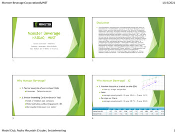
SECTION 2: SET-UP AND INSTALLATIONP81 2 3 4 5 6NEUTRAL1 2 3 4 5 6 7 81 2 3 4 5 6 7 8 9 10 11 12 13P6P724v24 vDCDC5vDC5vDC24vDCP16NEUTRALP105vDC1 2 3 4 5 6 7 8 9 10 11 12 OLET24 vACNEUTRAL4 3 2 1BLACKREDP5MDB24 vACSold-Out Indicators6 5 43 2 1WHITEBROWNBLUEP9P4A P4COL 1COL 2COL 3COL 4KEYCOL 5COL 6COL 7COL 8COL 9COL 10COL 11COL 12S118 17 16 15 14 13 12 11 10 9 8 7 6 5 4 3 2 1BLACKREDGREENREADY TO VEND INDICATORS5vDCTemperatureSensorKEYP3If the door is closed, the controller will return to the SalesMode. If credit exists, the credit amount will be displayedafter returning to the Sales Mode.5vDC18 17 16 15 14 13 12 11 10 9 8 7 6 5 4 3 2 LACKGREYPURPLEBROWNBLUEGREENORANGEYELLOWWHITE18 17 16 15 14 13 12 11 10 9 8 7 6 5 4 3 2 11) No response from the selection switches is receivedwithin approximately five minutes;2) The Service Mode Button is pressed a second time;3) The “rtn” function is activated.9 8 7 6 5 4 3 2 1CONTROLLERBLACKREDGRNDP11The controller will automatically return to the Closed-DoorMode ChuteSensor6 5 4 3 2 1Escape, CancelIncrease, NextDecrease, PreviousOK, Accept, Save5vDCP15J17REDBROWNGREENYELLOWHome Sensor/Door yP21234Usage1 2 3 4 5 6 7 8 9 10 11 12 13 14 15 165vDCMeaningREDNEUTRALButtonBLACKKEYBROWN8 7 6 5 4 3 2 1The first four selection switches are used to navigatethrough the service routines as follows:Mode Switch& HHCInterfaceDex PhoneJackP1All programming of the vender options is done in theService Mode. To enter the Service Mode, open the venderdoor and press and release the Service Mode Button whichis located on the controller board (see Figure 2.7).BLACKBROWNREDKEY10 9 8 7 6 5 4 3 2 1Four-Button ProgrammingPowerFigure 2.7RelayOutputsVend Motor/Encoder
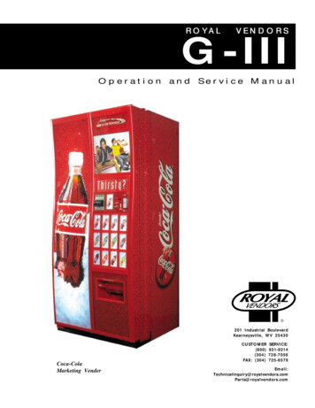
EXTERNAL MENUK.O.ProgrammingFlowchartErorCASHSALErtnLAnG EnG Frn GEr ItatinELitPortEnb YEAR nth EUSECTION 2: SET-UP AND INSTALLATIONINTERNAL (SERVICE) MENUrFrGEnbErorSel. Switch Test (1-13)CPOtEStVEndSLSOdSPStoP deG SEtP StordAydAyIf Configuration 2 is enabled,the following menus will appear:rELYbLC1CnpEnbCO1 - CO12FanPASSS/O Test (1-12)StrtStoP SELdAydAyHour HourbLC2EnbHtrPASSWORD PROTECTED MENUStrtStoP SELdAydAydISCEnbStrtStoP SELSALEdAydAyPrICHour HourConC1C2C3C4CStSC5rStSC6C7C8C9C10LESSOVErFrE bLC dSC Lit FrGSdEP1 - 13ALLSet by selectionCCOC Con CCU ACCPrEULitHour HourCASHOPt1 - OPt9 CLrLitLitrtnStSdSPHour HourLED Segments, Correct Change Lamp& Sold Out Lamp Flash TesttuFLStrtrUndStrtStoP SELdAydAyrAtERHour Hour6/01Rev. A
SECTION 2: SET-UP AND INSTALLATIONCode LevelsIndividual modes are identified by displaying their code asfollows:CODEDESCRIPTIONErorCPOtUFLtEStPASS CASH SALE PrIC StS Con CCOC PrEU LAnG tinE rFrG bLC1* bLC2* dISC* OVEr* SdEP* rUnd*rtnError Display ModeCoin Payout ModeTube Fill ModeTest Vend ModePassword ProtectionCash Counter Display ModeVend Counter Display ModeSelection Price Setting ModeSpace to Sales Programming ModeMachine Configuration Mode (C1-C10)Correct Change OnlyPreview Data Password ModeLanguage Selection ModeTime/Date Setting ModeRefrigeration Control ModeBlock Selection ModeBlock Selection ModeDiscount Setting ModeManual Switch Over-ride ModeBy-selection Setting ModeRemote Vend Mechanism RoutineReturn to Sales Mode* If optional features (C2 under Con Menu) are disabled, these menus will not appear, and will not apply.The exception to this rule is SdEP which will not appear,but will still apply. Code level modes preceded with a “ ” are consideredsensitive to incorrect setup procedures. Therefore, they canonly be accessed after a predefined and unchangeablepassword has been entered via the selection switches. Oncethe password has been entered, all functions will be available.“PASS” will be displayed only if the password has not beenentered. Otherwise the function codes will be displayed aslisted above.The password is entered via the first four selection switcheswhile the controller is displaying “PASS.” The password mustbe entered within 10 seconds in the following order: 4-2-3-1.The display will go blank after the first selection switch ispressed. After completing the sequence, press (ENTER). If thepassword is not recognized, the display will remain blank butwill reappear if no buttons are pressed.Page 8Code Level ExplanationERROR DISPLAY MODEIf (ENTER) is pressed at the “Eror” prompt, the controllerwill enter the error display mode. If no errors haveoccurred since the last error reset, the display will show“nonE.” If an error has been detected since the last errorreset, the display will show the first error summary codethat has occurred.EXAMPLE: “CJXX” would indicate a column jamerror.If (ENTER) is pressed, the controller will display thedetailed error for the summary code. (UP) and (DOWN)will cycle through any remaining error detail codes. If the(ABORT) is pressed while displaying any detailed code,the controller will return to the summary code. If the(ABORT) is pressed while displaying any summarycode, the controller will return to the code level.If (ENTER) is pressed and held for two seconds duringthe display of a detailed error code, that error will becleared. If other currently accessed detailed errors exist,the next error will now be displayed. If no other errors ofthis type exist, the next error summary code will bedisplayed, or “nonE” if no other errors exist.Vend Mechanism Error “UEnd”The “UEnd” prompt indicates that at least one vendmechanism error has been detected. If the (ENTER) isactivated, the controller will Indicating a column jam error.Chute sensor is active for more than 5 mins.Indicating a home sensor error.Indicating an encoder error.Indicating a “rabbit” error.If more than one detailed error is presented, they may beviewed using (UP) and (DOWN) . These errors arecleared via the HHC or Service Mode.Control System Error “Ctr1”After the “Ctrl” prompt, the controller will display:dSIndicating a door switch error.RanIndicating RAM error.ACLO Indicating low AC.SFIndicating a scaling factor error.ISIndicating an inlet sensor error.IbIndicating the inlet is blocked.G-III Vender
SECTION 2: SET-UP AND INSTALLATIONSelection Switch Error “SEL”After the “SEL” prompt, the controller will display“SSXX” where ‘XX’ indicates the selection switch hasbeen active for more than 15 seconds while in the salesmode.Space to Sales Error “StS”After the “StS” prompt, the controller will display“UAXX” where ‘XX’ represents the column which is notassigned to a selection.Coin Changer Error “CHAr”After the “CHAr” prompt, the controller will display:“CC”“tS”“IC”Indicating a changer communications error.Indicating a tube sensor error.Indicating an inlet chute blocked error (no coinssensed in the acceptor for over 96 hours).“tJXX” Indicating a tube jam error (where ‘XX’indicates the tube number).“CrCH” Indicating a changer ROM checksumerror.“EE”Indicates excessive escrow.“nJ”Indicating a coin jam.“LA” Indicating a low acceptance rate.The “CC” error is cleared when proper communication isestablished. The “CSF” error is cleared upon power up orvia the HHC or service mode. The “IC” error is clearedwhen a coin is accepted. All other “CHAr” errors are resetvia the HHC or Service Mode, or when the conditioncausing the error no longer exists.Bill Acceptor Error “bUAL”After the “bUAL” prompt, the controller will H”Indicating a bill communication error.Indicating a full bill stacker.Indicating a defective motor.Indicating a bill jam error.Indicating a bill acceptor ROMchecksum error.“bOPn” Indicating an open cash box.“bS”Indicating a sensor error.Card Reader Error “Crdr”After the “Crdr” prompt, the controller will display:“CrC” Indicating a card reader communication error.“Crxy” Indicating an error number reported by the cardreader, where ‘x’ is a hexadecimal digitrepresenting the card reader code and ‘y’ is ahexadecimal digit representing themanufacturer-specific sub-code.Refrigeration Error “rFrG”After the “rFrG” prompt, the controller will display:“SEnS” Indicating a temperature sensor error.“CoLD” Indicating temperatures three or moredegrees below the compressor cut-out setting.“Hot” Indicating cabinet temp. is above limit.“CnPr” Indicating that the compressor is notcooling within 30 minutes of turning on, or;“Htr” indicating the heating system has failed toincrease 1 deg. per hour while heater is on.The “CoLD” error is cleared when the temperature risesabove three degrees below cutout. The “Hot” error iscleared when the temperature drops to the “SetP”. The“SEnS” error is cleared when a sensor is detected. Theremaining “rFrG” errors can also be cleared via the HHC orservice mode.External MenuAccess the External Menu by entering your 4-digitpassword (factory set 4-2-3-1), when the main door isclosed.The External Menu contains:Errors (Eror)Cash Counts (CASH)Sales Counts (SALE)Return (rtn)Note: Use the Preview Data Password Mode (PrEU)under the password protected menu to display or changethe current password.The “bC” error is cleared when proper communication isestablished. The “bSF “ error is cleared upon power up,via the HHC or the service mode. The remaining errorsare cleared whenever the validator reports no errors and isenabled (the validator is “enabled” when it acceptsmoney).G-III VenderPage 9
SECTION 2: SET-UP AND INSTALLATIONInternal (Service) MenuCOIN PAYOUT MODEIf (ENTER) is pressed at the “CPO”prompt, the controller will enter the coin payout mode anddisplay the lowest coin value that can be paid out. Using(UP) or (DOWN) will allow the operator to cycle throughthe coin values that are routed to the coin tubes. If(ENTER) is pressed, a payout of the displayed value willbe made. Coins will continue to payout as long as(ENTER) is held down. If (ABORT) is pressed at any time,the controller will return to the “CPO” prompt. Press the(UP) button to proceed to the next prompt “tuFL”.TUBE FILL MODEIf (ENTER) is pressed at the “tuFL”prompt, the controller will enter the coin tube fill mode. Inthis mode, the operator is allowed to deposit any coin intothe coin changer’s acceptor where that coin tube is notfull. The tube inventory level will be displayed after eachcoin is accepted. If (ABORT) is pressed at any timeduring this operation, the controller will return to the“tuFL” prompt. Press the (UP) button to proceed to thenext prompt “tESt”.NOTE: This is the only method of loading the tubes thatensures exact cash accountability.TEST VEND MODEIf (ENTER) is pressed at the “tESt”prompt, the controller will enter the test vend mode.Using (UP) or (DOWN) will allow the operator to togglebetween the following �Column Vend TestSelection Switch TestSold Out Test (per column)Display TestRelay Test- (CnP, FAn, Lit, Htr)Column Vend Test “UEnd”If (ENTER) is pressed at the “UEnd” prompt, the controller will enter the column vend test mode. The display willshow “CO 1”, which represents “column 1”. Pressing(UP) and (DOWN) cycle through the available columns.If (ENTER) is pressed, the controller will attempt to vend aproduct from the displayed column. Vends made while inthis routine will affect only the test vend counters. If(ABORT) is pressed at anytime during this operation, thecontroller will return to the “UEnd” prompt. Press the(UP) button to proceed to the next prompt “SL”.Page 10Selection Switch Test “SL”If (ENTER) is pressed at the “SL” prompt, the controllerwill enter the selection switch test mode. The display willshow “SL 4”, which indicates that the fourth selectionswitch was pressed last. When any selection switch ispressed, it will be represented by the right two digits. Thelast selection switch pressed will remain on the displayuntil the service mode timer expires or the (ABORT)button is pressed and held for two seconds, this will returnthe controller to the “SL” prompt. Press the (UP) buttonto proceed to the next prompt “SO”.Sold Out Test “SO”If (ENTER) is pressed at the “SO” prompt, the controllerwill enter the sold out test mode. The display will show“C 1X”, which represents column one, if X is (0) columnone is not sold out and if X is (1) column one is sold out.Pressing (UP) and (DOWN) cycles through the availablecolumns. Pressing the (ENTER) button has no action.Pressing (ABORT) button will return the controller to the“SO” prompt. Press the (UP) button to proceed to thenext prompt “dSP”.Display Test “dSP”If (ENTER) is pressed at the “dSP” prompt, the controllerwill enter the display test mode. The display, correctchange only light and sold out light will run a diagnostictest until service timer expires or if the (ABORT) button ispressed. Press the (UP) button to proceed to the nextprompt “rELY”.Relay Test Mode “rELY”If (ENTER) is pressed at the “rELY” prompt, the controllerwill enter the relay test mode by displaying “CnpX.” If(ABORT) is pressed in this mode, the user will return tothe “rELy” prompt. Using (UP) or (DOWN) will allow theoperator to toggle between the following or RelayEvaporator Fan RelayLight RelayHeater RelayIf (ENTER) is pressed at the “CnPX” prompt, the controllerwill enter compressor relay test. If X (0) the relay is notactivated and if X (1) the relay is activated. Pressing(ENTER) will toggle the display between “0” and “1.”For all relaysX 1 relay is activated;X 0 relay is not activated.Pressing (ABORT) at the “rELy” display will bring you outto “tESt”. Press the (UP) button to proceed to the nextprompt “PASS”.G-III Vender
SECTION 2: SET-UP AND INSTALLATIONPassword Protected MenuPASSWORD PROTECTION“PASS” will be displayed only if thepassword has not been entered. Otherwise the functioncodes will be displayed as listed under the Code Levelsection of this manual. The password is entered via thefirst four selection switches while the controller isdisplaying “PASS.” The password must be entered within10 seconds in the following order: 4-2-3-1. The display willgo blank after the first selection switch is pressed. Aftercompleting the sequence, press (ENTER). If the passwordis not recognized, the display will go back to “PASS”.CASH COUNTERDISPLAY MODEIf (ENTER) is pressed at the “CASH” prompt, the controller will enter the non-resettable cash display mode bydisplaying “CASH”/“XXXX”/“XX.XX” where the ‘X’srepresent total cash over machine life. A decimal will bedisplayed in the appropriate position with the lower fourdigits. If the cash amount is less than five digits long, theupper four digits are not displayed. Using (UP) or(DOWN) will cycle through each selection as “CANN”“XXXX/XX.XX,” where the “NN” indicates the selectionand the ‘X’s represent the resettable cash per selection. If(ABORT) is pressed anytime during this operation, thecontroller will return to the code level. Press the (UP)button to proceed to the next prompt “SALE”.VEND COUNTERDISPLAY MODEIf (ENTER) is pressed at the “SALE” prompt, the controllerwill enter the non-resettable vend display mode bydisplaying “SALE/“XXXX”/“XXXX.” where the ‘X’srepresent the number of all paid vends over machine life. Ifthe sales amount is less than five digits, the upper fourdigits will not be displayed. Using (UP) or (DOWN) willcycle through each selection as “SLNN”/“XXXX/XXXX.”where the “NN” indicates the selection and the ‘X’srepresent the resettable number of vends for that selection. A decimal will be displayed in the right-most positionwith the lower four digits. If (ABORT) is pressed anytimeduring this operation, the controller will return to the“SALE” prompt. Press the (UP) button to proceed to thenext prompt “PrIC”.G-III VenderSELECTION PRICESETTING MODEIf (ENTER) is pressed at the “PrIC” prompt, the controllerwill enter the selection price setting mode. The display willshow “Pr 1” if the machine is in multi-price mode, or “SPrI”if the machine is in single-price mode.The G-III Vender is shipped from the factory in multi-pricemode with a .75 cent vend price.Notes:1. In the single-price mode, the price for selection 1 is theprice for all selections. Single-price is displayed as“SPrI” instead of “Pr1” as a reminder to the operatorthat the machine is currently in single-price mode.In the multi-price mode, individual selection prices can bechanged using the (UP) and (DOWN) to display “PrXX,”where ‘XX’ is the selection number, or choose “ALL” tochange the prices for all selections. If (ENTER) is pressed,the display will show the current price for the displayedselection. Using (UP) or (DOWN) will increase or decreasethe price. Holding (UP) or (DOWN) for more than fiveseconds will cause the price to change at 10 times thenormal rate. When the desired price is on the display,pressing (ENTER) will save that price, while pressing(ABORT) will return to the selection level without saving.Press the (UP) button to proceed to the next prompt “StS”.SPACE-TO-SALESPROGRAMMING MODEIf (ENTER) is pressed at the “StS” prompt, the controllerwill enter the space-to-sales programming mode bydisplaying “OPtn,” where ‘n’ is the current optionselected; “CStS” for custom configuration, or “rStS”.Using (UP) or (DOWN) will allow the operator to cyclethrough all 12 available space-to-sales options “OPt1”“OPt9,” “CLr” as well as the “CStS” and “rStS” options.When one of the “OPt1”-“OPt9”, “CLr” options are on thedisplay, pressing (ENTER) will select that space-to-salesoption and return to the code level. If one of the “OPt1”“OPt9,” “CLr”, “CStS,” or the “rStS” option is displayedand (ABORT) is pressed, the user will return to the “StS”prompt without changing the settings.NOTES:1.If (ENTER) is pressed at “CLr”, the “StS” settings willreset to none.2. There is a decal, located on the inner door, that showsthe relationship between columns and selections.3. If the clear program is used without assigning anycolumns, the LED with read “Sold-out”.Page 11
SECTION 2: SET-UP AND INSTALLATIONCustom Space-to-Sales Programming “CStS”If (ENTER) is pressed at the “CStS” prompt, the customspace-to-sales programming mode is entered. The displaywill show “SL XX” and alternate this message with either“nonE,” if no columns are assigned to the selection, or asequence of numbers (XX) that represent the columnscurrently assigned to the selection. Pressing (UP) or(DOWN) will cycle through the remaining selections, plusthe “SAUE” {save} option. Pressing (ABORT) at thispoint will move the user to the “SAUE” option, wherepressing (ENTER) will save the changes, and pressing(ABORT) will return to the “CStS” prompt without savingany of the changes.If (ENTER) is pressed at a “SLXX” prompt, the displaywill show “Cnn” where ‘nn’ is the column number.Pressing (UP) or (DOWN) will cycle through all 12columns. If (ENTER) is pressed at any column indicator,the display will change to “CnnY” where “Y” will be ‘1’ ifcolumn “nn” is currently assigned to the selection, or ‘0’ ifit is not. (UP) and (DOWN) can be used to change theassignment status of the column. Pressing (ABORT) atthis time will return the user to the “Cnn” display withoutchanging the status of the column, while pressing(ENTER) saves the displayed status of the column.Pressing (ABORT) at any column indicator (“Cnn”)returns the user to the “SLXX” display. Pressing(ABORT) at this point will move the user to the “SAUE”option. While at the “SAUE” prompt, pressing (ENTER)saves the custom space-to-sales settings and returns to thecode level (“StoS”), while pressing (ABORT) returns tothe “CStS” prompt without saving the settings. Press the(UP) button to proceed to the next prompt “rStS”.NOTE: Assigning a column to a selection does not clearprevious assignment of that column. Care must be takento ensure that a column is not mistakenly doubleassigned or left unassigned.SPACE TO SALES SETTINGS12COLUMNSOpt 1Opt 2Opt 3Opt4Opt 5Opt 6Opt 7 Opt 8Sel 11,6,71,2,7,81,2,7,81,2,7,81,2,7,81,2,7,81,2,3 1,2,31,2,3Sel 21,6.71,2,7,81,2,7,81,2,7,83,91,2,7,84,54,54,5Sel 32,81,2,7,81,2,7,81,2,7,843,9666Sel 42,81,2,7,81,2,7,81,2,7,854,1077,87,8,9Sel 5333,93,9658910Sel 6343,93,910691011Sel 74544,101111101112Sel 85654,1012121112Sel 999651,2,7,81,2,7,812Sel 101010106Sel 1111111111Sel 1212121212Sel 131,6,71,2,7,81,2,7,81,2,7,8Page 12Opt 9Recommended Space-to-Sales “rStS”If (ENTER) is pressed at the “rStS” prompt, a recommended space-to-sales configuration is calculated, basedon first choice attempts since StS was last changed. Thedisplay will flash “SL 1” and alternate this message witheither “nonE,” indicating that no columns should beassigned to selection 1, or a sequence of numbers thatrepresent columns that should be assigned to selection 1.Pressing (UP) or (DOWN) will cycle through the remaining selections. Pressing (ENTER) or (ABORT) will movethe user to the “SAUE” option, where pressing (ENTER)will save the recommended space to sales or pressing(ABORT) will return the “StS” prompt without saving thechanges. Press the (UP) button to proceed to the nextprompt “Con”.MACHINE (C1-C10)CONFIGURATION MODEIf (ENTER) is pressed at the “Con” prompt, the controllerwill enter the machine configuration mode by displaying“C1-1,” which designates configuration option number 1.If (ABORT) is pressed while at the “Cn” level, thecontroller will return to the code level. Pressing (UP) or(DOWN) will allow the selection of available configurationoptions. Pressing (ENTER) will change the display to “CnX” where “n” is the configuration number and “X” is thecurrent status of the option. The status is changed using(UP) or (DOWN). Pressing (ENTER) saves the status ofthe current option and returns the user to the “Cn”prompt, while pressing (ABORT) returns to the “Cn”prompt without saving. From the “Con” prompt, press(UP) to proceed to the next prompt “CCOC”.Royal Vendors recommended E.V.S. configurationsettings:Con 1 - (1) Multi priceCon 2 - (1) Opt features onCon 3 - (0) Greeting displayedCon 4 - (0) Totals disabledCon 5 - (0) Mis resetCon 7 - (0) Five minute timer usedCon 8 - (1) Force attempt enabledCon 9 - (0) Multi purchase disabledCon 10 - (0) Bill escrowSingle/Multi-PriceThis configuration chooses between thesingle-price and multi-price settings by pressing (UP) or(DOWN). In the single-price mode, th
of information. The machine type such as RVCC (Royal Vendors Coca Cola). It also contains the vender model number such as 804-9 (capacity of 804 twelve ounce cans / 9 selections). How to read a Serial Number: The first 4 numbers represent the year the vender was produced The 5th and 6th numbers represent the week within the