Transcription
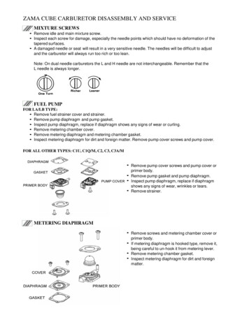
ZAMA CUBE CARBURETOR DISASSEMBLY AND SERVICEMIXTURE SCREWS Remove idle and main mix ture screw. Inspect each screw for damage, especially the needle points which should have no deformation of thetapered surfaces. A damaged needle or seat will result in a very sensitive needle. The needles will be difficult to adjustand the carburetor will always run too rich or too lean.Note: On dual needle carburetors the L and H needle are not interchangeable. Remember that theL needle is always longer.FUEL PUMPFOR LA/LB TYPE: Remove fuel strainer cover and strainer. Remove pump diaphragm and pump gasket. Inspect pump diaphragm, replace if diaphragm shows any signs of wear or curling. Remove metering chamber cover. Remove metering diaphragm and metering chamber gasket. Inspect metering diaphragm for dirt and foreign matter. Remove pump cover screws and pump cover.FOR ALL OTHER TYPES: C1U, C1Q/M, C2, C3, C3A/M Remove pump cover screws and pump cover orprimer body. Remove pump gasket and pump diaphragm. Inspect pump diaphragm, replace if diaphragmshows any signs of wear, wrinkles or tears. Remove strainer.METERING DIAPHRAGM Remove screws and metering chamber cover orprimer body. If metering diaphragm is hooked type, remove it,being careful to un-hook it from metering lever. Remove metering chamber gasket. Inspect metering diaphragm for dirt and foreignmatter.
INLET NEEDLE VALVE If the carburetor is equipped with a plastic metering disk, remove it carefully. The disk must be smoothand free from cracks or chipped edges. The center tip that fits into the metering lever hole must be secureand not broken or worn. The following instructions apply to all models. Remove metering lever screw. Remove metering lever, pin, metering lever spring and inlet needle valve. Inspect the metering lever. It should not be worn where it contacts the inlet needle valve and meteringdisk. Inspect inlet needle valve. The tip should not be deformed where it contacts the seat.WELCH PLUG Under the extreme conditions of a clogged idle portand channel, it may be necessary to remove thewelch plug. Do this operation very carefully. If thecarburetor is equipped with the priming pump, donot attempt to remove the welch plug unless youare certain the check valve in the idle chamber ismalfunctioning. Use a small 2/32 to 3/32 inch diameter sharppointed punch to pierce the welch plug. Just below the welch plug there is a thin casting wall where the idle and secondary holes are located.Punching through this area will ruin the carburetor body casting. Let the punch just pierce the welch plug,then carefully pry the welch plug out of the body casting. If the carburetor is equipped with the plastic filling in the idle chamber, it will be unusable when the welchplug is removed.Note: It is often un-necessary to remove the welch plug. Test for plugged progression holes by sprayingcarb cleaner into the L needle hole. If cleaner sprays out the progression holes there is no need to removethe welch plug.LOCATION CHART FOR PIERCING WELCH PLUGS
NOZZLE Test the main nozzle by blowing air by mouth through the H needle feed hole with a small hose. With theneedle open 2 turns open air should flow through, but you should not be able to suck air back. Before removing nozzle assembly, make sure the main mixture screw was already removed. If the carburetor is equipped with a pressed in nozzle assembly, do not attempt to remove it unless youare certain it is malfunctioning. If it is necessary to remove, carefully press it out with steel rod or punchslightly smaller in diameter than the nozzle. If the carburetor is equipped with a screw in nozzle assembly, remove it in the same manner as a normalscrew. If the carburetor is equipped with strainer and C-ring type, remove main welch plug, then remove C-ringand retainer. It is not necessary to remove nozzle. The strainer and retainer type is not repairable. Clean them using gasoline and compressed air.CARBURETOR BODY Clean the carburetor body. Channels can be cleaned by blowing through the idle and main adjustingorifices with spray carburetor cleaner. Do not soak in dip tank type cleaner. Do not use wires or drills toclean orifices. Inspect the operation of the throttle valve and lever.REASSEMBLY* Replace all worn parts and make sure that all parts are clean before they are reassembled into carburetorbody.NOZZLE Make sure the main mixture screw was removed, before reassembling the nozzle assembly.If nozzle assembly is a pressed in type, put a light oil film on the outside of the nozzle check valve cage.Carefully press the nozzle into the carburetor body until it is just flush with the metering chamber.If the carburetor is a strainer and C-ring type, install the strainer and C-ring. Lay the main welch plug intothe cavity and press it firmly with a flat end punch to expand it tightly against the sides of the cavity. If nozzle assembly is a screw in type, reassemble in the same manner as a normal screw.WELCH PLUG Lay the welch plug into the cavity. If the welchplug is circle shape, press it firmly with a flat endpunch to expand it tightly against the sides of thecavity. If the welch plug is oblong shape, press itfirmly with oblong punch. Lay the welch plug into the cavity. Press it firmlywith oblong punch. It is best to use sealer forsealing around the welch plug.INLET NEEDLE VALVE Inspect the metering lever and the pin.Assemble the lever onto the pin and rotate the pin. The lever should fit easily on the pin and not stick.Install the inlet needle valve, metering spring, metering lever, pin and retaining screw.Adjusting the metering lever. The Zama "Z" gauge is designed to adjust all models. Hold the gaugeagainst the body as shown using the proper side designated for the model you are adjusting. The end ofthe metering lever should touch the gauge. A strait edge can also be used as described on the next page.(A) If the metering lever is the same as Figure a in the following schematic, place a straight edge or ZamaZ gauge across the carburetor body. The free end of the metering lever should be 0 to 0.3 mm - 0 to0.012" below the straight edge.(B) If the metering lever is the same as Figure b in the following schematic, the free end of the meteringlever should be flush with the cavity floor. (1.7mm to 2.0 mm - 0.067" to 0.078" below the metering gasketflange of carburetor body).
ADJUSTING THE METERING LEVER HEIGHTZama Z-gaugeFigure aFigure bIf the metering lever is too high, push down on the free end of the lever, then carefully push down on the inletneedle, if the metering lever is too low, pry up carefully on the free end of the lever. Make sure the metering lever spring is seatedat the bottom of the casting pocket and underthe dimple in the metering lever. If the metering lever is too high, push down onthe free end of the lever, then carefully pushdown on the inlet needle, if the metering leveris too low, pry up carefully on the free end ofthe lever.METERING DIAPHRAGM AND FUEL PUMP Install the fuel strainer to the pump coverusing a flat end punch of a diameter nearlyequal to the inside of the strainer.METERING CHAMBER FOR ALL CUBE TYPES: C1U, C1Q/M, C2, C3, C3A/M If the carburetor is equipped with a plastic disk,install it onto the metering lever by placing themolded tip into the hole in the free end of themetering lever. Install the metering chamber gasket, meteringdiaphragm, metering chamber cover and screws.Metering chamber gasket and metering diaphragmshould be assembled in the proper order. Install the fuel strainer using a flat end punch of adiameter nearly equal to the inside of the strainer.Push the screen straight into the casting to thebottom of the bore.
FUEL PUMP FOR ALL CUBE TYPES: C1U, C1Q/M, C2, C3, C3A/M Install the pump diaphragm, pump gasket,pump cover and screw. Pump diaphragm andpump gasket should be assembled in theproper order.METERING DIAPHRAGM AND PUMP FOR LA/LB TYPE: Install the metering chamber gasket, meteringdiaphragm, and metering chamber cover.Metering chamber gasket, and meteringdiaphragm should be assembled in properorder. Install the pump gasket, pump diaphragm andpump cover. Pump gasket and pumpdiaphragm should be assembled in properorder. Carefully install the fuel strainer. Push thescreen straight into the casting to the bottomof the counter bore. Install the gasket, fuelstrainer cover and screw.
If thecarburetor is a strainer and C-ring type, install ring. Lay main welch plug into the cavity and press it firmly with a flat end punch to expand it tightly against the sides of the cavity. If nozzle assembly is ascrew intype, reassemble the same manner as normal screw. WELCH PLUG Lay the welchplug into cavity. If